
Pinch Analysis Cuts Chemical Utility Costs by up to 30%
The Problem Table Algorithm targets utility savings without disrupting plant production.
Pinch Analysis is a systematic process integration methodology that optimises heat exchanger networks to reduce external utility usage, driving a significant thermal efficiency improvement in chemical plants. Chemical processing facilities operate continuous, high-temperature processes that require substantial thermal inputs. Distillation columns, reactor jackets, evaporators, and utility systems like boilers and cooling towers consume vast quantities of fossil fuels and electricity. Under the regulatory framework of 2026, including the UK Emissions Trading Scheme (UK ETS) and the EU Energy Efficiency Directive (EED), reducing Scope 1 and Scope 2 carbon emissions is vital for maintaining a profitable manufacturing facility.
Pinch Analysis resolves this challenge by evaluating the entire thermal system of a process plant rather than focusing on individual unit operations. By systematically matching hot streams that require cooling with cold streams that require heating, this methodology establishes the absolute minimum energy targets before engineers design any hardware modifications. Applying these rigorous thermodynamic principles regularly leads to a 10 to 30 per cent reduction in thermal utility consumption and associated greenhouse gas emissions.
What is Pinch Analysis?
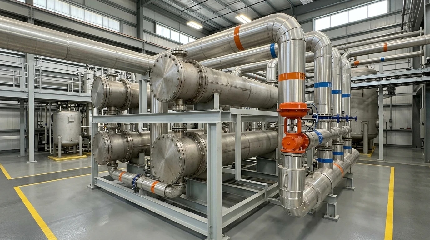
Process heat integration historically relied on localised, heuristic designs. Process engineers matched a single hot process stream with a single cold process stream, often overlooking the broader plant balance. Pioneered in the late 1970s and early 1980s by B. Linnhoff and his colleagues, Pinch Analysis shifts the perspective to the entire system.
Defining the Thermodynamic Pinch Point
The foundation of Pinch Analysis lies in compiling a comprehensive thermal profile of the plant. Engineers gather data for all hot streams (requiring cooling) and cold streams (requiring heating). By combining the heat capacity rates of these individual streams within distinct temperature intervals, they construct a single Hot Composite Curve and a single Cold Composite Curve on a Temperature-Enthalpy (T-H) diagram.
The cold composite curve is shifted horizontally until it approaches the hot composite curve as closely as possible without crossing. The point of closest approach is determined by the minimum approach temperature (ΔTmin), which represents the smallest allowable temperature driving force for heat transfer. The specific temperature at this closest approach is the Pinch Point. The Pinch Point acts as a thermodynamic barrier that divides the process into two distinct thermal regions:
- Above the Pinch: This region operates as a net heat sink, requiring only external heating (hot utilities). No cooling utilities are permitted here.
- Below the Pinch: This region operates as a net heat source, requiring only external cooling (cold utilities). No heating utilities are permitted here.
The Concept of Targets Before Design
A core principle of Pinch Analysis is the philosophy of "Targets before Design". Traditional energy audits often propose immediate, localised equipment modifications, such as installing a new heat exchanger on a visible hot stream. Pinch Analysis calculates the absolute thermodynamic minimum for both heating (Qh,min) and cooling (Qc,min) utilities before any physical network is designed or modified. This target-driven approach establishes a clear performance benchmark, ensuring that capital expenditure is directed only toward projects that yield actual thermal benefits.

Pinch analysis identifies the thermodynamic minimum energy requirement of your process — then designs the heat exchanger network to achieve it.
The Three Golden Rules of Pinch Analysis
To achieve the minimum utility targets identified by the composite curves, engineers must adhere strictly to three primary thermodynamic constraints. These constraints are known as the Golden Rules of Pinch Analysis. Violating these rules introduces cross-pinch heat transfer, leading to a severe energy penalty.
Rule 1: Do Not Transfer Heat Across the Pinch Point
Heat must never be transferred from a process stream above the pinch to a process stream below the pinch. Because the region above the pinch is a net heat sink and the region below is a net heat source, transferring heat across the boundary reduces the system's internal heat recovery capacity.
Rule 2: Do Not Use External Cooling Above the Pinch
Since the region above the pinch has a net deficit of heat, introducing cold utilities (such as cooling water or air coolers) removes thermal energy that the process needs. This cooling must be compensated for by importing an equivalent amount of external heat, thereby increasing the hot utility requirement.
Rule 3: Do Not Use External Heating Below the Pinch
The region below the pinch has a net surplus of heat. Introducing hot utilities (such as steam or hot oil) adds unnecessary thermal energy to a system that already requires cooling. This excess heat must eventually be removed by cold utilities, increasing the demand on cooling systems.
The Double Penalty Phenomenon
When engineers violate these Golden Rules, the process suffers from the double penalty effect. If a heat exchanger transfers 1 MW of heat across the pinch point, the hot utility demand above the pinch increases by exactly 1 MW, and the cold utility demand below the pinch also increases by 1 MW. The plant pays twice for a single design error: first to purchase the extra heating utility, and second to remove that same heat through the cooling utility.
| Operational Region | Thermodynamic Role | Permitted Utilities | Prohibited Actions |
|---|---|---|---|
| Above the Pinch | Net Heat Sink | Hot Utilities Only (Steam, Hot Oil) | No Cold Utilities, No Heat Export |
| Below the Pinch | Net Heat Source | Cold Utilities Only (Cooling Water, Chilled Water) | No Hot Utilities, No Heat Import |
Core Mathematical Tools: Problem Table Algorithm and Grand Composite Curve
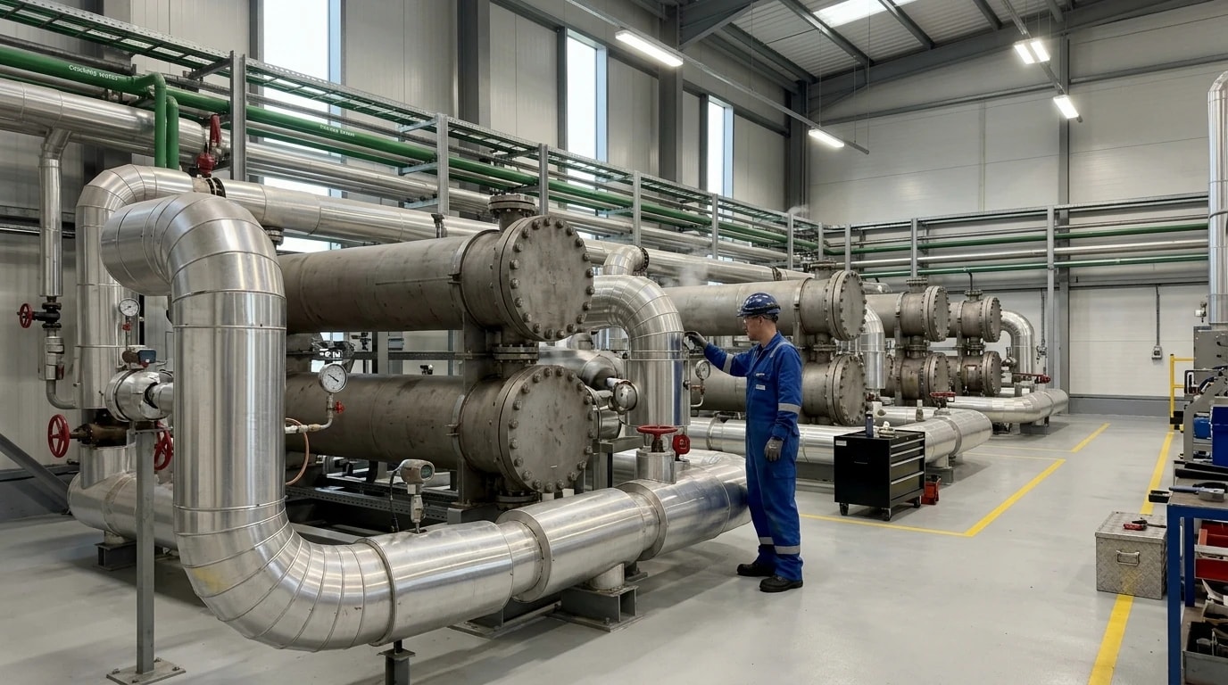
While graphical composite curves provide clear visual intuition, manual curve construction is impractical for modern chemical plants containing dozens of streams. Thermal engineers rely on algebraic and numerical tools to calculate targets with absolute precision.
The Problem Table Algorithm
The Problem Table Algorithm, developed by B. Linnhoff and J. Flower, is a rigorous mathematical cascade approach used to establish exact utility targets and identify the pinch temperature. The algorithm removes visual approximation from the design process through a structured sequence:
- Temperature Shifting: The actual supply and target temperatures of all streams are shifted to create a common temperature scale. For hot streams, temperatures are shifted downward by subtracting half of the minimum approach temperature (ΔTmin/2). For cold streams, temperatures are shifted upward by adding half of the minimum approach temperature (ΔTmin/2).
Where Th∗ and Tc∗ are the shifted temperatures, Th and Tc are the actual stream temperatures, and ΔTmin is the chosen minimum approach temperature.
- Interval Creation: The shifted temperatures are sorted in descending order to partition the process into temperature intervals.
- Enthalpy Balance: For each interval, the net heat balance is calculated by subtracting the heat demand of cold streams from the heat supply of hot streams. This identifies whether an interval has a heat surplus or a heat deficit.
- Heat Cascading: Heat is cascaded from the highest temperature interval down to the lowest. If the initial cascade results in negative heat flows (which represents thermodynamically impossible heat transfer from cold to hot), the cascade is infeasible.
- Feasibility Adjustment: A quantity of external heat (Qh,min) equal to the largest negative value is injected at the top of the cascade. The cascade is run again, resulting in a feasible heat cascade where all heat flows are positive or zero.
The point in the feasible cascade where the heat flow is exactly zero defines the shifted Pinch Temperature. The external heat injected at the top is the minimum hot utility target (Qh,min), and the heat leaving the bottom of the cascade is the minimum cold utility target (Qc,min).
The Grand Composite Curve (GCC)
The Grand Composite Curve is constructed by plotting the net heat flow (residual heat cascade) against the shifted temperatures. Unlike the main composite curves, the GCC highlights the specific temperature levels at which the process requires heating or cooling.
The GCC is essential for utility selection and optimisation. It displays "pockets" where process heat can be transferred internally without external utilities. Outside these pockets, the curve shows where and at what temperatures external heat must be supplied or rejected. Process design teams use the GCC to match utility steam levels (high, medium, or low pressure) to the process profile. This ensures that high-grade heat is not wasted on low-temperature duties, allowing the use of cheaper, low-pressure steam or waste heat from other units.
Integrating Major Unit Operations
Chemical manufacturing processes contain major energy-consuming units such as distillation columns, reactors, and combined heat and power (CHP) systems. Optimising these systems requires integrating them with the background process via the Grand Composite Curve.
Distillation Column Integration
Distillation columns require large thermal inputs at the reboiler and reject heat at the condenser. If a column is placed across the Pinch point (with the reboiler above and the condenser below), it acts as a pathway for heat transfer across the pinch. This violates Rule 1, resulting in a double utility penalty: the column requires its full external heating and cooling duties, saving no energy.
To achieve thermal integration, the column must be placed entirely above or entirely below the Pinch point.
- Above the Pinch: The column's condenser can reject heat to cold process streams that need heating, reducing the overall hot utility demand of the plant.
- Below the Pinch: The column's reboiler can absorb heat from hot process streams that need cooling, reducing the overall cold utility demand.
If the column operating temperatures do not naturally align, process engineers can adjust the column pressure to shift the reboiler and condenser temperatures, allowing for successful integration.
Reactor System Placement
Reactors often generate or consume significant thermal energy. Exothermic reactors represent major heat sources. If an exothermic reactor operates above the Pinch, its reaction heat can be cascaded down to heat other cold streams, reducing the plant's external heating needs. If it operates below the Pinch, its heat must be removed by cold utilities, adding to the cooling water load. Process engineers use the GCC to evaluate the feed and product streams of reactors, adjusting reaction pressures or feed preheat levels to ensure reaction heat is recovered productively.
Combined Heat and Power (CHP) Integration
Combined heat and power systems, such as gas turbines or steam turbine cogeneration systems, must be integrated based on Pinch principles. The heat rejected from a heat engine (for example, turbine exhaust gas or steam) must be delivered above the Pinch point. This rejected heat replaces expensive external hot utility, achieving high fuel efficiency. If the engine's heat is rejected below the Pinch, it cannot be recovered by the process and simply increases the cooling load, wasting the thermodynamic benefit of the CHP system.

Pinch analysis identifies the thermodynamic minimum energy requirement of your process — then designs the heat exchanger network to achieve it.
Designing and Retrofitting Heat Exchanger Networks (HEN)
Translating thermodynamic targets into physical reality requires designing or modifying the Heat Exchanger Network (HEN). This is performed using systematic design rules and specialised process integration software evaluated by process design teams.
The Grid Diagram and Matching Rules
The Grid Diagram is the primary tool used to design a HEN. Unlike a traditional process flow diagram, streams are represented as horizontal lines (hot streams running left-to-right, cold streams running right-to-left) with temperature scales. The Pinch Point is drawn as a vertical dashed line splitting the diagram.
To design a network that meets the target energy recovery without crossing the pinch, process engineers must apply strict matching rules at the Pinch boundary:
- Stream Number Rule: The number of streams being matched must support the temperature constraints. Above the pinch, the number of hot streams (Nhot) must be less than or equal to the number of cold streams (Ncold). Below the pinch, the number of hot streams must be greater than or equal to the number of cold streams.
- Heat Capacity Rate Rule: To ensure the temperature difference between the streams does not fall below ΔTmin, the heat capacity rates (CP) of the matched streams must satisfy:
- Above the Pinch: CPhot≤CPcold
- Below the Pinch: CPhot≥CPcold
If these rules are violated during matching, the temperature difference between streams will compress, forcing the use of external utilities to bridge the gap.
Retrofitting Existing Chemical Plants
While grassroots designs offer complete freedom, most industrial projects involve retrofitting existing, operational chemical plants. Retrofit projects face substantial physical and economic constraints:
- Spatial Limits: Existing heat exchangers are physically fixed in place, and piping routes are constrained by structural steel and safety clearances.
- Pressure Drop Constraints: Re-routing process streams through additional exchangers increases pressure drop, potentially requiring pump or compressor upgrades.
- Equipment Reuse: To maintain low capital expenditure (CAPEX), design teams prioritise reusing existing exchanger shells and tubes.
Retrofit methodologies, such as path-relaxation and loop-breaking, allow engineers to simplify the network. If a proposed design requires too many new piping runs, engineers can break a heat recovery "loop" by accepting a slightly higher utility consumption in exchange for a much simpler, cheaper installation. Despite these physical limitations, retrofits based on Pinch Analysis regularly achieve utility cost reductions of 10 to 30 per cent with payback periods under two years.
Targeting Decarbonisation: Achieving Regulatory Compliance
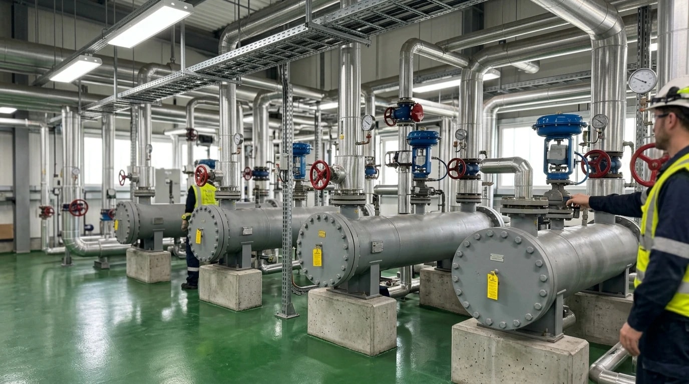
Optimising thermal efficiency in chemical plants is no longer just an operational preference; it is key to compliance under modern environmental regulations.
The Regulatory Framework in 2026
Industrial operators in the UK and Europe face a stringent regulatory environment. The UK Emissions Trading Scheme (UK ETS) and the European equivalent place a high financial value on carbon dioxide emissions. Unrecovered heat that must be supplied by natural gas combustion directly increases a plant's carbon liability.
Furthermore, the UK Climate Change Levy (CCL) imposes taxes on energy consumption, while the updated EU Energy Efficiency Directive (EED) mandates that large industrial enterprises carry out regular energy audits or implement a certified energy management system. Conducting a Pinch Analysis study and retrofitting the HEN provides a scientifically validated route to comply with ISO 50001:2018 (Energy Management Systems), offering documented evidence of continuous thermal efficiency improvement in chemical plants.
Quantifiable Carbon and Capital Benefits
Reducing hot utility requirements by 10 to 30 per cent has a direct, linear impact on a facility's carbon footprint. For a plant relying on gas-fired boilers, this level of utility reduction translates directly into equivalent Scope 1 greenhouse gas savings.
Additionally, lowering cold utility demands reduces Scope 2 electricity consumption. Cooling towers, air coolers, and refrigeration compressors consume substantial electrical power to operate fans and pumps. By minimising the heat rejected to cold utilities, the electrical load of these auxiliary systems decreases significantly.
Beyond emissions compliance, thermal integration often debottlenecks existing utility systems. If a plant's boiler house or cooling tower is operating at maximum capacity, expanding production would normally require expensive utility upgrades. By applying Pinch Analysis to reduce the baseline utility demand, the plant can expand chemical production capacity within the limits of its existing utility infrastructure, avoiding major capital investments.
Step-by-Step Implementation of a Pinch Analysis Study
Applying Pinch Analysis to a complex chemical process requires a structured, multi-phase engineering programme. Following this systematic approach ensures that data is validated, targets are realistic, and retrofits are economically viable.
Step 1: Data Extraction and Validation
The accuracy of any process integration study depends on the quality of the input data. Engineers must review Piping and Instrumentation Diagrams (P&IDs), process simulation models, and historical Distributed Control System (DCS) logs to identify every stream requiring heating or cooling. For each stream, they must extract:
- Supply Temperature (Ts): The temperature at which the stream is currently available.
- Target Temperature (Tt): The temperature the stream must reach for downstream processing.
- Heat Capacity Rate (CP): The product of the mass flow rate (m) and the specific heat capacity (cp).
- Enthalpy Change (Q): The total thermal load of the stream, calculated as Q=CP⋅(Tt−Ts).
Engineers must validate this data to ensure the plant was operating under representative steady-state conditions during data collection, accounting for seasonal or turndown variations.
Step 2: Choosing the Minimum Approach Temperature (ΔTmin)
Selecting the target ΔTmin is an economic optimisation step. A very small ΔTmin (for example, 5°C) maximises process-to-process heat recovery, reducing utility consumption (OPEX) to the absolute minimum. However, low temperature driving forces require extremely large heat transfer surface areas, significantly increasing the capital cost of the heat exchangers (CAPEX). Conversely, a larger ΔTmin (such as 25°C) reduces exchanger sizes but increases utility consumption.
Process design teams typically evaluate this trade-off by plotting CAPEX and OPEX against ΔTmin to find the optimum point that minimises total lifetime cost. In chemical manufacturing, this optimum usually falls between 10°C and 20°C.
Step 3: Numerical and Graphical Targeting
With the stream data and selected ΔTmin validated, engineers run the Problem Table Algorithm to calculate the Pinch temperature and utility targets. They construct the Composite Curves and Grand Composite Curve to map the plant's thermal profile, identifying exactly how much steam, hot oil, cooling water, or refrigeration is required at each temperature level.
Step 4: Network Design and Optimisation
Finally, engineers use the Grid Diagram to design or retrofit the heat exchanger network. By matching streams according to the Pinch design rules, they ensure that no heat is transferred across the Pinch. After establishing a thermodynamically optimal network, they perform loop-breaking and path-relaxation to simplify the design, ensuring that the physical modifications are easy to construct, operate, and maintain. This structured methodology allows chemical manufacturing plants to achieve a 10 to 30 per cent reduction in utility costs while maintaining high process safety and reliability.
This article reflects the independent analysis and editorial opinion of EnerTherm Engineering. Product names, trademarks, and brands mentioned belong to their respective owners. EnerTherm Engineering is not affiliated with, endorsed by, or a licensee of any third-party software or product mentioned unless explicitly stated.

Managing Director — EnerTherm Engineering
Dr. François Pierrel is Managing Director of EnerTherm Engineering with over two decades of expertise in thermal design, heat transfer, and industrial energy optimisation. He holds a PhD in Heat Transfer from Cranfield University and a Post-Doctorate from Heriot-Watt University.
