DTS Exchangers Recover 65-85% of Pharma Waste Heat
How Double Tube Sheet exchangers and heat pumps cut HVAC thermal loads by up to 52%.
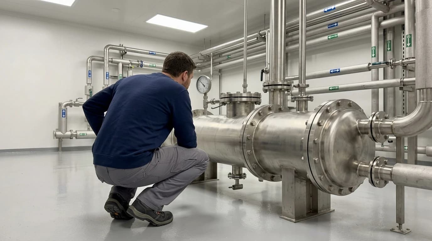
A Double Tube Sheet (DTS) heat exchanger is a high-integrity shell-and-tube thermal device. Designed with two separate tube sheets at each end of the tube bundle, it prevents cross-contamination between utility streams and high-purity process fluids. Managing energy costs and carbon footprints is a primary challenge in pharmaceutical manufacturing. Facilities must operate continuously under rigid environmental conditions, requiring high thermal inputs for clean utilities. Process engineers must reduce utility bills while maintaining compliance with stringent quality guidelines. This balance makes thermal optimisation essential.
The Critical Need for Waste Heat Recovery in Pharmaceutical Industry Facilities
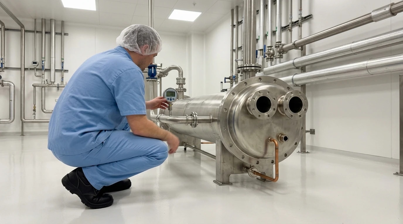
To maintain sterile environments, pharmaceutical manufacturing sites operate intensive air-handling and water purification systems. These clean utilities are the primary contributors to a facility's overall carbon footprint and operating expenses. Implementing waste heat recovery in pharmaceutical manufacturing is therefore a priority for energy managers seeking to meet corporate decarbonisation targets.
HVAC and Water for Injection (WFI) Energy Profiles
Clean room HVAC systems and WFI generation typically consume 40 to 60 per cent of a pharmaceutical facility's total energy. HVAC networks require extensive heating, cooling, dehumidification, and reheating to maintain exact parameters within classified spaces. To prevent contamination, these systems require high air-change rates, ranging from 20 to 600 air changes per hour depending on the cleanliness class. Meanwhile, WFI systems historically relied on multi-effect distillation, which requires continuous thermal input to vaporise feed-water before condensing it into sterile liquid. These demands translate into substantial utility costs and significant Scope 1 and Scope 2 carbon emissions.
Thermodynamic Potential of Validation-Ready Systems
Most of the thermal energy fed into clean room HVAC and WFI systems is eventually rejected into the atmosphere or sewer systems as low-grade waste heat. Capturing this thermal energy allows process plants to substantially reduce primary energy demands. Validated heat recovery systems can recover between 65 and 85 per cent of this process waste heat. Implementing these systems requires specialised engineering to ensure that energy-saving measures do not compromise product sterility. When correctly designed, these recovery loops provide an effective path towards manufacturing decarbonisation.

Pinch analysis identifies the thermodynamic minimum energy requirement of your process — then designs the heat exchanger network to achieve it.
Double Tube Sheet (DTS) Exchanger Design and Cross-Contamination Prevention
In standard industrial heat recovery, simple plate-and-frame or single tube sheet shell-and-tube exchangers are common. However, these configurations present severe risks in pharmaceutical processing. If a tube wall or gasket fails, utility fluids and pure process fluids can mix, leading to catastrophic product contamination. To prevent this, process engineers specify DTS exchangers for critical thermal duties.
The Anatomy of a Double Tube Sheet
A DTS heat exchanger features two separate tube sheets at each end of the tube bundle. High-purity process fluid flows through the inner tubes, while the utility medium flows through the surrounding shell. The first tube sheet seals the utility fluid within the shell jacket, while the second seals the process fluid within the tubes. This design creates a physical atmospheric gap. If a leak occurs at either tube sheet joint, the fluid exits into this visible gap rather than entering the opposing fluid path.
Leak Detection and Physical Segregation Mechanics
The physical gap between the two tube sheets acts as a fail-safe detection chamber. Instrumentation, such as conductivity sensors, pressure transmitters, or simple visual sight glasses, monitors this chamber. Because the gap is open to the atmosphere or a low-pressure collection system, leaks are immediately diverted and detected before cross-contamination can occur. This mechanical separation eliminates the risk of pinhole leaks or joint failures contaminating sterile products with non-potable utility water or industrial steam.
Compliance with EU GMP and MHRA Standards
Regulatory compliance is the primary constraint for any process modification in a pharmaceutical facility. Under EU GMP Annex 1 (2022 edition) and the UK's Medicines and Healthcare products Regulatory Agency (MHRA) regulations, manufacturers must implement rigorous contamination control strategies. Traditional single-wall heat exchangers are generally deemed insufficient for high-purity heat recovery due to the potential for unmonitored cross-contamination. The DTS design provides the documented physical segregation required to satisfy MHRA and GMP inspectors, allowing facilities to proceed with heat integration projects without risking regulatory non-compliance.
Corrosive Condensate and the CIP Thermal Penalty
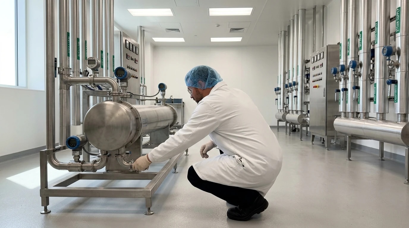
Clean utility processes generate significant high-temperature waste streams, but recovering this energy is chemically and thermally demanding. Clean-in-Place (CIP) and clean steam systems represent two of the largest thermal loads, each presenting unique engineering challenges.
The Corrosive Nature of Pure Condensate
Unlike utility steam, clean steam is generated from highly purified water, typically processed via reverse osmosis or deionisation. Containing virtually no dissolved minerals or ions, this pure water is highly aggressive. It is 'hungry for ions' and actively leaches metals from surrounding piping, leading to severe rouging or corrosion.
Furthermore, standard volatile corrosion inhibitors, such as amines, are strictly forbidden in clean steam feed-water to avoid contaminating the drug product. Consequently, this highly corrosive condensate must be handled with specialised metallurgy, such as electropolished 316L stainless steel. It cannot be directly recycled back into the clean steam generator as untreated feed-water due to cross-contamination risks.
Clean-in-Place (CIP) Thermal Profiles
CIP systems are essential for sterilising process vessels, reactors, and piping networks between batch runs. These cycles require high thermal energy, with temperatures reaching up to 100 °C during the hot wash and sanitisation phases. Once wash cycles are complete, these high-temperature fluids are typically discharged to the effluent system, carrying valuable thermal energy with them. This rapid dumping of hot water represents a major thermal penalty and drives up industrial energy bills.
Designing for High-Temperature Validation
To recover heat from corrosive clean steam condensate and hot CIP effluent, thermal design teams specify DTS heat exchangers. The DTS design allows engineers to transfer heat from the corrosive, non-recyclable condensate or CIP effluent to pre-heat incoming purified water or cold make-up water. By utilising DTS exchangers, the clean utility stream remains completely segregated from the waste stream. This protects the integrity of the fresh feed-water while recovering between 65 and 85 per cent of the waste thermal energy.

Pinch analysis identifies the thermodynamic minimum energy requirement of your process — then designs the heat exchanger network to achieve it.
Integrating Industrial Heat Pumps with Process Chiller Loops
Decarbonisation strategies are increasingly transitioning from high-energy steam systems to industrial heat pumps. These heat pumps can tap into process chiller loops to recover low-grade waste heat and upgrade it to low-pressure hot water (LPHW) for HVAC reheating, significantly reducing thermal loads.
Regulatory Drivers: EED III and I.S. 399 Energy Efficient Design
Energy efficiency regulations across the UK and Europe are pushing pharmaceutical facilities to phase out fossil-fuelled steam boilers. The European Union's Recast Energy Efficiency Directive, known as EED III (Directive (EU) 2023/1791), mandates strict energy consumption reductions. It requires companies consuming more than specified energy thresholds to implement certified energy management systems.
Similarly, the Irish standard I.S. 399:2021 (Energy Efficient Design) outlines a structured framework for integrating energy efficiency directly into the design phase of capital projects. These standards encourage engineering teams to look beyond traditional steam boilers and embrace electrified, high-efficiency thermal systems.
Upgrading Low-Grade Chiller Waste Heat
Process chillers are ubiquitous in pharmaceutical plants, providing the cooling required for bioreactors, crystallisation vessels, and HVAC dehumidification. These chillers reject massive amounts of low-grade heat, usually between 15 °C and 25 °C, to the atmosphere via cooling towers. Industrial heat pumps can capture this low-grade heat from the chiller condenser loop. By applying mechanical compression, the heat pump elevates this energy to a useful temperature, typically 70 °C to 80 °C.
HVAC Reheat Integration and Thermal Load Reductions
The upgraded thermal energy from the industrial heat pump is supplied as LPHW to the facility's HVAC reheat coils. During dehumidification, air is cooled below its dew point to remove moisture and must subsequently be reheated to meet clean room comfort and process standards. Using heat pumps to supply this reheat load, rather than relying on natural gas steam boilers, delivers thermal load reductions of up to 52 per cent. This integration substantially reduces Scope 1 emissions and optimises the overall coefficient of performance (COP) of the combined heating and cooling utility networks.
Pinch Analysis for Multi-Batch Pharmaceutical Plants
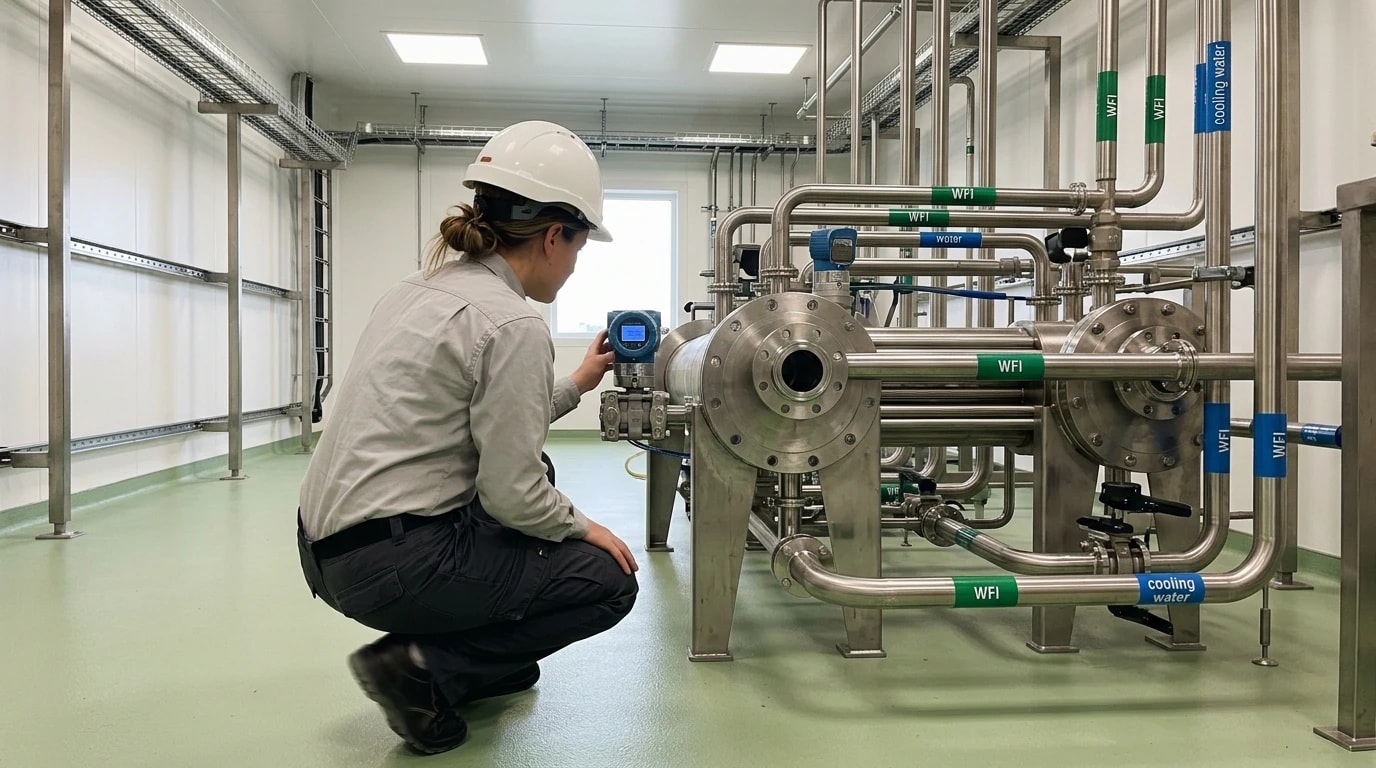
Optimising thermal efficiency in a pharmaceutical facility requires more than installing individual heat exchangers. Because drug manufacturing is predominantly a batch process, heat generation and heat demand often occur at different times. Thermal design consultancies apply Pinch Analysis methodologies to design optimised, integrated thermal networks that can handle these time-shifted loads.
Pinch Analysis Principles in Batch Processing
Pinch Analysis is a systematic methodology used to design heat exchanger networks that minimise external utility use. By plotting hot and cold process streams on temperature-enthalpy graphs, engineers determine the thermodynamic limit of heat recovery, known as the 'pinch point'.
In continuous processes, heat is transferred directly from hot to cold streams. In batch operations, however, a hot CIP discharge might occur hours before a cold WFI make-up stream requires heating. To apply Pinch Analysis successfully, engineers must incorporate the time dimension, identifying overlapping thermal windows where direct heat exchange is possible.
Thermal Energy Storage for Time-Shifted Loads
To bridge the time gap between heat availability and demand, process designs often integrate thermal energy storage (TES) systems. A TES system utilises insulated water vessels to store recovered heat during a high-temperature discharge, such as a CIP rinse or a bioreactor clean-down.
When a cold process utility requires heating later, the stored hot water is pumped through a DTS heat exchanger to pre-heat the incoming stream. This combined approach of Pinch Analysis, TES, and DTS heat exchangers ensures continuous, stable heat integration despite the discontinuous nature of batch manufacturing.
Combined Energy Integration Flowsheet
The integration of chiller loops, industrial heat pumps, CIP waste streams, and DTS heat exchangers into a unified LPHW loop can be mapped to show how energy flows through the facility. The following diagram illustrates the relationship between these utility systems:
This flowsheet demonstrates how low-grade heat from chillers and high-grade heat from CIP processes are combined and upgraded to serve the facility's HVAC reheat requirements. This integrated system maximises the use of recovered energy and minimises the reliance on external fossil-fuel utilities.
Material Selection and Maintenance of DTS Exchangers
Because of strict sterile requirements and corrosive process fluids, DTS heat exchangers must be designed and maintained with extreme care. The selection of materials and surface finishes is critical to preventing microbial growth and ensuring long-term thermal performance.
| Component / Feature | Standard Specification | Purpose / Compliance |
|---|---|---|
| Tube Metallurgy | 316L Stainless Steel (1.4404) or Titanium | Corrosion and rouging resistance |
| Internal Surface Finish | Ra ≤ 0.38 µm to 0.6 µm | Minimises micro-crevices and biofilm adhesion |
| Passivation | Electropolishing | Enhances chromium oxide layer protection |
| Gasket Materials | PTFE / EPDM / FKM (USP Class VI) | Chemical and thermal compatibility |
| Drainability | Straight tube / Vertical mounting | Prevents pooling of standing water |
Metallurgy and Surface Finishes
The primary material used for DTS heat exchangers in the pharmaceutical industry is 316L stainless steel, which offers high resistance to corrosion and rouging. For more demanding applications, such as high-temperature clean steam condensate, titanium or exotic alloys may be selected. The internal product-contact surfaces are typically polished to a surface roughness of Ra ≤ 0.38 µm to 0.6 µm, often followed by electropolishing. This smooth finish prevents bacterial adhesion and biofilm formation, facilitating effective cleaning during routine sanitisation cycles.
Gasket and O-Ring Configurations
Gaskets and O-rings must withstand high process temperatures and aggressive cleaning chemicals. Common elastomeric materials include polytetrafluoroethylene (PTFE), ethylene propylene diene monomer (EPDM), and fluoroelastomers (FKM). These seals must comply with relevant sanitary standards, such as US FDA 21 CFR 177 regulations and USP Class VI biocompatibility tests. Regular inspection and replacement of these seals are necessary to maintain the integrity of the DTS barrier and prevent external leaks.
Minimising Fouling and Cleanability
DTS heat exchangers are designed to be completely drainable on both the tube and shell sides to prevent standing water, which can promote microbial growth. The units are typically configured with straight tubes or vertical mounting to ensure gravity-assisted draining. During maintenance, the external gap between the two tube sheets is inspected for signs of leakage, providing a clear indication of tube or joint wear before cross-contamination can occur. This proactive monitoring ensures the long-term reliability and compliance of the waste heat recovery infrastructure.
This article reflects the independent analysis and editorial opinion of EnerTherm Engineering. Product names, trademarks, and brands mentioned belong to their respective owners. EnerTherm Engineering is not affiliated with, endorsed by, or a licensee of any third-party software or product mentioned unless explicitly stated.

Managing Director — EnerTherm Engineering
Dr. François Pierrel is Managing Director of EnerTherm Engineering with over two decades of expertise in thermal design, heat transfer, and industrial energy optimisation. He holds a PhD in Heat Transfer from Cranfield University and a Post-Doctorate from Heriot-Watt University.
