Why Chemical Plants Recover Furnace Heat for Steam
A technical review of furnace recovery, exchanger fouling and DSEAR controls.
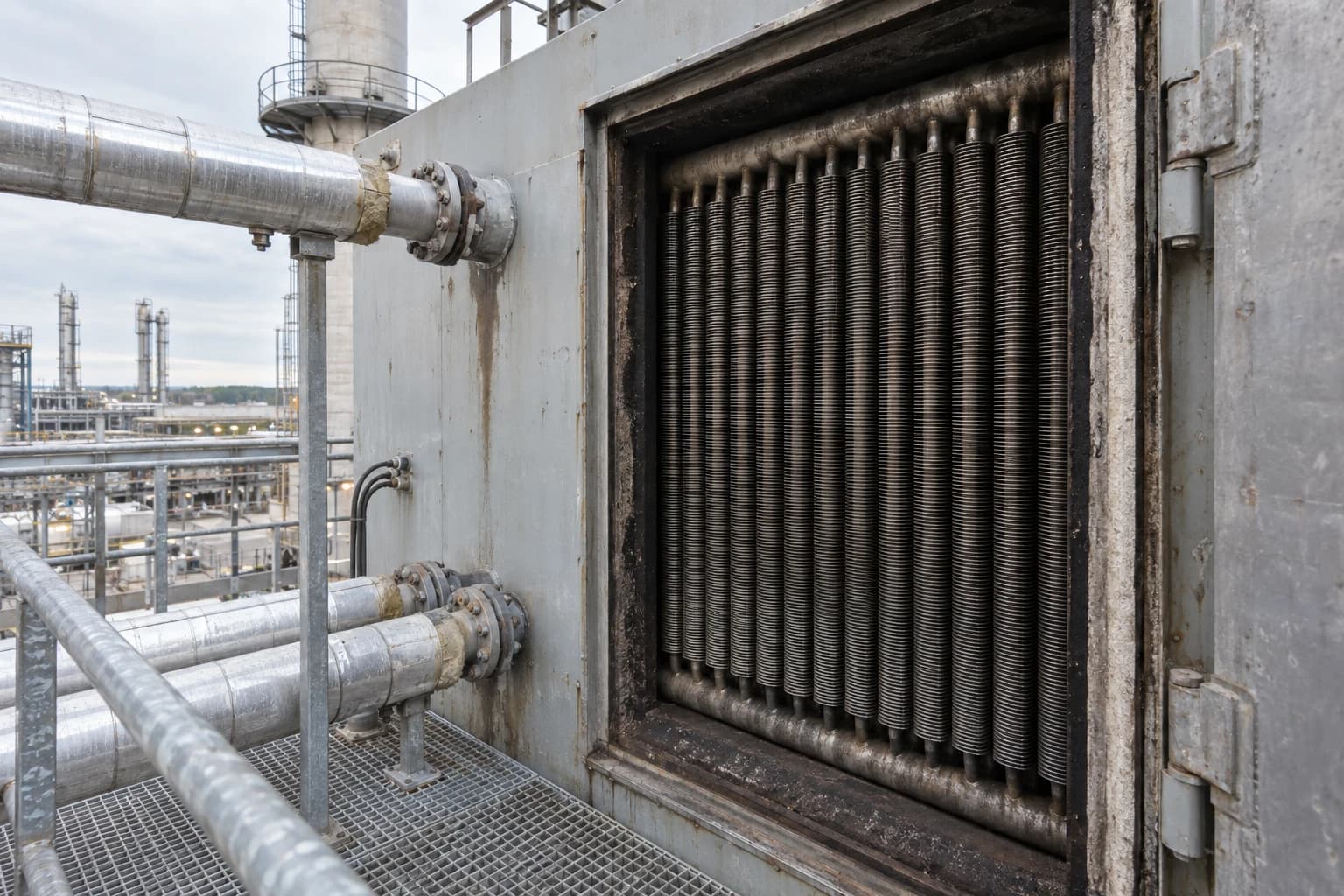
A waste heat recovery system in the chemical industry captures energy from furnace flue gas, hot process streams or other high-temperature exhausts and transfers it into useful steam instead of rejecting it to atmosphere or cooling water.
A fired heater running at stable throughput can send a large, continuous heat flow up its stack. Chemical plants recover part of that flow because steam already has clear duties: reboiling distillation columns, tracing lines, stripping, drying products, driving turbines, heating reactors and supporting utilities. Replacing boiler-generated steam with recovered steam reduces fuel demand without changing production chemistry.
This is a heat-integration project, not a bolt-on boiler purchase. The strongest schemes match the temperature, availability and cleanliness of a heat source with dependable steam demand. They must also protect furnace operation, meet hazardous-area duties and retain flexibility for plant upsets, turnarounds and changing product campaigns.
Why furnace heat is well suited to steam generation
Steam is a useful thermal carrier
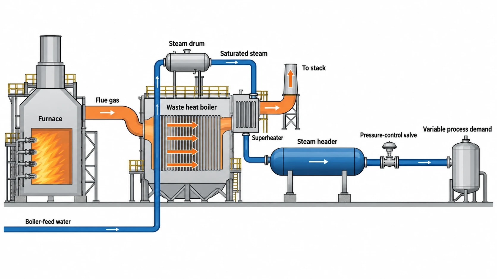
Steam accepts heat at a nearly constant temperature while water changes phase. That makes it a good match for hot flue gas and many chemical process streams. A waste heat boiler can turn treated boiler-feed water into saturated steam, then add superheat where the receiving header requires it.
The steam header is a buffer between heat supply and demand. A furnace may operate continuously while a reactor batch or distillation service varies. Plant controls, pressure-control valves and properly sized steam drums can absorb part of that difference.
Recovered steam can displace steam from a package boiler or site utility boiler. Avoided boiler fuel, feedwater treatment, combustion air and stack losses form the economic case. Project value rises when recovered steam replaces higher-pressure steam that the process needs, rather than creating low-pressure steam with no stable consumer.
Furnaces provide a concentrated heat source
Fired heaters concentrate combustion heat in an accessible flue-gas path. Depending on furnace arrangement and process duty, recovery equipment may sit in the convection section, downstream of the radiant box or in a dedicated waste heat boiler arrangement. HSE guidance identifies furnaces and boilers as chemical-plant equipment used for waste heat recovery, steam generation and off-gas destruction.
A process engineer must establish the heat available after protecting the original furnace duty. The aim is a reliable operating point that avoids poor draft, unstable combustion, unacceptable back-pressure, corrosive condensation and loss of process temperature control.
Chemical plants often have several heat sources
A site energy review should examine more than the main fired heater. Candidate sources commonly include:
- Furnace and thermal oxidiser flue gas.
- High-temperature reactor effluent after reaction heat has served process control.
- Distillation bottoms, condensers and column side streams.
- Compressor aftercoolers and interstage coolers.
- Hot product streams heading to storage or downstream treatment.
- Incinerator and off-gas destruction systems.
- Boiler blowdown and flash steam.
A heat source becomes a recovery opportunity only when a receiving demand exists at an appropriate temperature during the same operating period. The European Commission’s Energy Efficiency BREF notes that heat recovery is unsuitable where production and demand profiles do not match.

Identify where your plant is losing energy and quantify the savings potential — our audits map every heat source, sink, and waste stream in your facility.
How waste heat recovery systems make steam
Waste heat boilers and economisers
A waste heat boiler places heat-transfer surfaces in a hot gas stream to generate steam. The arrangement may include an economiser to preheat boiler-feed water, evaporator banks to generate saturated steam, a steam drum for phase separation and superheater surfaces where the steam header needs a higher temperature.
An economiser alone may suit a site that needs hotter feedwater but cannot justify a new steam-generation circuit. It reduces boiler fuel use indirectly by lowering the sensible heat required in the existing boiler.
The design depends on source temperature, flue-gas composition, steam pressure, operating hours, pressure-drop allowance and maintainability. A system recovering heat from clean natural-gas combustion has a different duty from one installed behind an oxidiser treating solvent-bearing exhaust.
Steam pressure determines recovery value
Higher steam pressure requires a higher saturation temperature. This sets the minimum useful temperature difference through the heat exchanger and limits flue-gas cooling. Engineers should map all steam headers, their pressure, normal and peak load, minimum turndown and boiler operating pattern.
| Recovery route | Typical use in a chemical plant | Key design question |
|---|---|---|
| Boiler-feedwater economiser | Reduce fuel to existing boilers | Is stack temperature sufficiently above acid-dew-point constraints? |
| Low-pressure saturated steam | Tracing, stripping, low-temperature heating | Does the header have steady demand during furnace operation? |
| Medium-pressure steam | Reboilers and process heating | Can the source sustain the required evaporation temperature? |
| Superheated steam | Turbine drives or defined process duties | Does the project justify the extra control and superheat surface? |
| Hot-water recovery | Wash systems, space heating or preheat | Would direct water heating recover more heat than steam generation? |
Steam pressure should follow the heat source and the customer. Forcing a low-grade source to create high-pressure steam can require a large heat exchanger, leave little temperature driving force and deliver disappointing performance. A cascade arrangement may be better: generate the highest useful steam pressure first, then use remaining heat for feedwater or process-water heating.
Heat recovery must preserve furnace performance
Furnace operation comes first. Added convection surfaces increase gas-side pressure drop and can alter draft behaviour. Induced-draught fan capacity, burner air-fuel control, oxygen trim, stack dispersion and emissions monitoring require review.
Flue-gas cooling can also cross an acid-dew-point threshold. Sulphur-containing fuels, halogens, acid gases and moisture increase corrosion risk. Metal temperature matters as much as average gas outlet temperature. A cold local surface can become the first failure point in an otherwise sound heat balance.
Pinch analysis identifies the best steam opportunity
Start with a site heat and mass balance
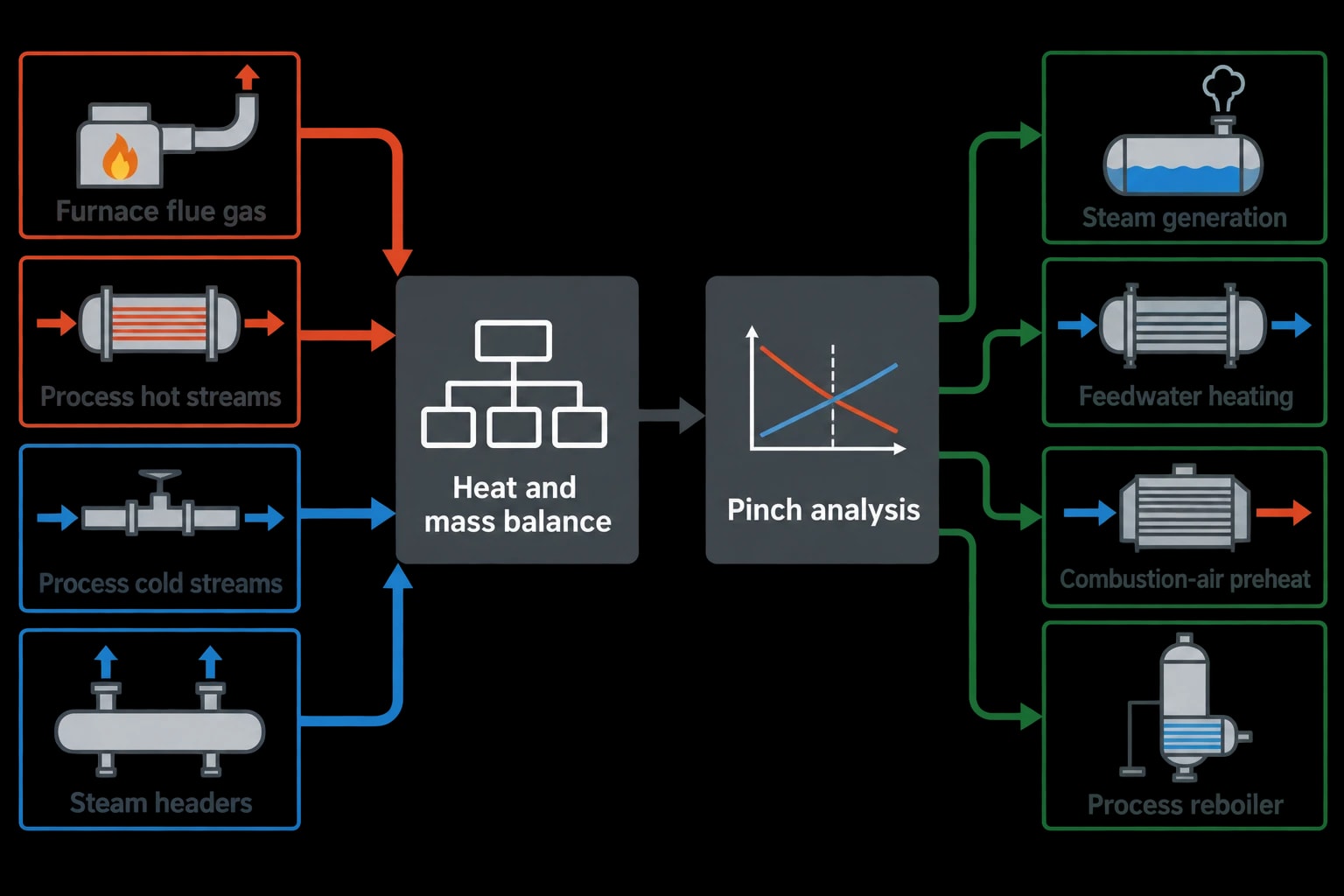
Chemical sites often identify an attractive stack before understanding the wider utility system. That sequence can miss a better match between process streams, steam headers and boilers. A heat and mass balance establishes where energy enters, where it leaves and where recovery can displace purchased fuel.
The assessment needs measured information, not nameplate estimates alone. Useful data includes:
- Flue-gas temperature, oxygen concentration, pressure and flow profile.
- Fuel flow and calorific-value basis.
- Boiler-feedwater flow, temperature, conductivity and blowdown.
- Steam flow and pressure by header.
- Process throughput, campaign pattern and batch timing.
- Cooling-water or air-cooler loads that reveal rejected heat.
- Existing heat-exchanger fouling history and maintenance intervals.
Thermal imaging can identify refractory losses, hot casings, poorly insulated valves and unexpected hot spots. It does not replace process measurements, but can direct field work towards losses otherwise hidden in a large unit.
Pinch analysis protects existing heat recovery
Pinch analysis compares process hot and cold streams to identify the minimum practical utility demand and the heat-exchanger network changes needed to reach it. In a chemical plant, it can reveal whether furnace heat should make steam, preheat combustion air, warm boiler-feed water, serve a reboiler or remain available for another process match.
A waste heat boiler can look attractive in isolation while blocking a lower-cost process-to-process heat exchanger. Conversely, pinch analysis may show that recovered steam is the sensible choice because the site needs a flexible utility rather than a fixed process match.
The analysis must use realistic operating cases. A polymer unit may change grade. A speciality chemical site may run batches with large gaps between heating demand. A bulk chemical plant may have a steady base load but a short shutdown window. Design around annual operating behaviour, including start-up, turndown and planned cleaning.
Choose an Energy Conservation Measure with clear boundaries
A good Energy Conservation Measure states the physical change, affected steam header, expected operating range, measurement boundary and project risks. “Recover furnace heat” is too broad. “Install a flue-gas economiser to raise deaerator inlet-water temperature within agreed stack-temperature and pressure-drop limits” is a testable measure.
EnerTherm Engineering’s seven-step energy-audit methodology can organise this work from initial consultation and site assessment through measurement, modelling, option development, prioritised Energy Conservation Measures, implementation planning and ongoing performance review. Power analysers, thermal imaging and utility measurements provide evidence for the model. The resulting project list should rank heat recovery against operational risk, capital cost, outage requirement, fuel savings, carbon reduction and maintainability.

Identify where your plant is losing energy and quantify the savings potential — our audits map every heat source, sink, and waste stream in your facility.
Design details that decide whether a project lasts
Materials, fouling and corrosion
Chemical-plant heat recovery equipment must suit actual stream chemistry. Flue gas may contain acidic compounds, particulates or condensable organic material. Process streams may bring chlorides, corrosive species, polymer deposits or solids. Selection of carbon steel, stainless steel, higher-alloy materials or lined equipment follows corrosion assessment, temperature, pressure and cleaning method.
Fouling changes performance gradually. A clean heat exchanger can meet the business case while a fouled heat exchanger drives higher fan power, reduces steam generation and restricts furnace capacity. The design should provide inspection access, online or offline cleaning arrangements, drainability, isolation and clearance around tube bundles, soot blowers or removable elements.
Thermal expansion also deserves attention. Hot gas ducts, heat-exchanger casings, tubes and connected pipework expand at different rates. Expansion joints, supports and nozzle loads must be designed as part of the whole system rather than added after layout decisions.
Water quality and two-phase control
Steam generation adds a water-side reliability duty. Boiler-feedwater treatment, dissolved oxygen control, conductivity, blowdown, drum-level control and steam separation determine whether tubes remain clean and protected.
Poor drum-level control can carry water into the steam header or expose evaporator tubes. Inadequate circulation can create local overheating. Process trips can sharply change available heat and cause pressure excursions. The control narrative should cover normal and low-load operation, furnace trip, loss of feedwater, fan failure, steam-header isolation and emergency shutdown.
Safety valves, venting, drains and blowdown routing must remain accessible and suitable for actual commissioning and maintenance sequences. A project that works only at full-rate steady operation has not completed its engineering.
Integrate emissions control
Heat recovery can affect emissions compliance. Lower flue-gas temperature may alter plume behaviour, condensation risk and downstream emissions-control equipment performance. New ductwork can introduce air ingress, changing oxygen readings and making combustion assessment less reliable.
Where recovery is associated with an oxidiser or off-gas destruction furnace, the review should confirm that the furnace continues to achieve its required destruction duty across anticipated flow and composition changes. Emissions monitoring and permit obligations should be considered during concept selection, not deferred to commissioning.
Process safety and hazardous-area compliance
DSEAR requires a documented assessment
The Dangerous Substances and Explosive Atmospheres Regulations 2002 require employers to assess risks from dangerous substances. Where an explosive atmosphere may occur, the assessment must classify hazardous areas into zones. HSE guidance explains that classification starts by identifying sources of release and assessing the likely frequency and duration of an explosive atmosphere.
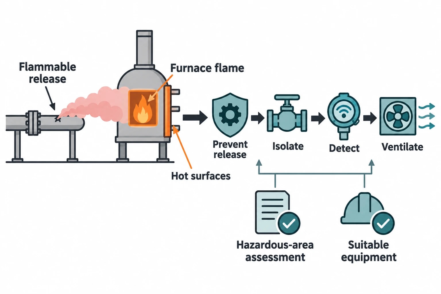
Recovery systems can introduce instruments, motors, dampers, pumps, heat tracing, actuators and electrical panels near process or exhaust streams containing flammable vapours. The hazardous-area assessment should identify relevant zones and support selection of suitable equipment, while considering non-electrical ignition sources.
Equipment selection is one control within a wider design. It does not make a leaking fuel line beside a furnace acceptable. HSE warns that a leak close to a heater can encounter flame or hot surfaces, so plant layout, isolation, detection, ventilation and release prevention remain central controls.
Use formal change control
A waste heat scheme changes process conditions, mechanical equipment and sometimes the safety case. Management of change should trigger appropriate process-hazard review, including HAZOP where the scale and hazard justify it. The review should test tube rupture, cross-contamination, loss of draft, excessive back-pressure, blocked drains, steam overpressure and flammable-release scenarios.
Safety instrumented functions may be affected when a project changes fuel, draft, furnace temperature or protective trips. The project team should establish whether existing Safety Integrity Level requirements remain valid and define necessary lifecycle work before installation.
Regulation, funding and performance verification
UK permits and EU requirements
In England, Part A(1) industrial installations must demonstrate energy-efficiency measures to obtain and comply with environmental permits. Environment Agency guidance directs operators towards an energy management system such as ISO 50001:2018 and the Energy Efficiency BREF. It also requires monitoring and annual reporting of energy efficiency for certain fossil-fuel energy-generating installations.
ISO 50001:2018, including Amendment 1:2024, provides a management framework rather than prescribing a particular heat-recovery technology. That suits chemical plants because each heat source, steam network and process constraint differs.
For EU operations, Directive (EU) 2024/1785 amended the Industrial Emissions Directive 2010/75/EU. It places greater emphasis on resource and energy use within environmental management systems and requires transformation plans for energy-intensive installations by 30 June 2030. UK sites should distinguish EU obligations from UK environmental permitting requirements, while recognising that energy-efficient BAT remains central to both.
Funding status needs careful interpretation
The Industrial Energy Transformation Fund closed to new applications in July 2025. The UK Government states that no successor fund is planned. It also states that £500 million was available across the programme through 2028 and that successful projects from earlier competition windows remain funded through completion.
A proposed project cannot assume a future IETF competition, but sites with an existing award should maintain delivery evidence, cost control and measurement records needed for the committed project.
Verify savings after commissioning
Steam savings cannot be measured directly because they are avoided fuel consumption. Measurement and verification should compare energy use before and after the project on a consistent basis, with adjustments for production rate, product mix, ambient conditions, steam export and other material operating changes.
The International Performance Measurement and Verification Protocol, IPMVP Core Concepts 2022, provides a framework for defining that work. An effective plan identifies meter locations, sampling periods, baseline conditions, calculation methods, uncertainty, responsibilities and reporting frequency before installation begins.
For a furnace heat recovery project, key operating measures normally include recovered steam flow, steam pressure, boiler-feedwater temperature, stack temperature, fuel rate, furnace oxygen, production throughput and heat-exchanger pressure drop. Trending these values helps operations teams identify fouling, bypass leakage, reduced heat demand or control instability before the savings case erodes.
This article reflects the independent analysis and editorial opinion of EnerTherm Engineering. Product names, trademarks, and brands mentioned belong to their respective owners. EnerTherm Engineering is not affiliated with, endorsed by, or a licensee of any third-party software or product mentioned unless explicitly stated.

Managing Director — EnerTherm Engineering
Dr. François Pierrel is Managing Director of EnerTherm Engineering with over two decades of expertise in thermal design, heat transfer, and industrial energy optimisation. He holds a PhD in Heat Transfer from Cranfield University and a Post-Doctorate from Heriot-Watt University.
