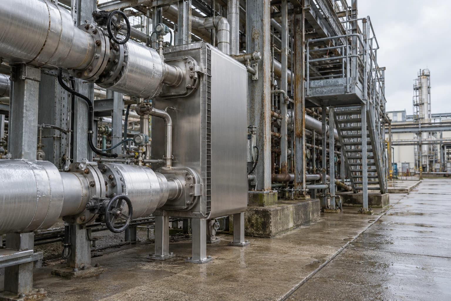
Heat Exchanger Network Optimisation Targets 10-35% Savings
Pinch analysis separates theoretical MER targets from feasible retrofit savings.
Heat exchanger network optimisation systematically improves process-to-process heat recovery, allowing hot streams to heat cold streams and reducing a chemical plant’s fuel, steam and cooling purchases. ISC3 reports that pinch-analysis applications in chemicals, oil refining, pulp and paper typically identify 10-35% energy-consumption savings opportunities.
That range is a useful benchmark, not a guaranteed project result. It describes opportunities identified through heat-integration analysis across varied sites and starting conditions. A brownfield retrofit must work within available exchanger area, pressure-drop allowance, fouling behaviour, process-control philosophy, plot space and turnaround programme. The best target is staged: establish the thermodynamic minimum, quantify the technically feasible retrofit, then approve measures that meet safety and commercial requirements.
For UK speciality chemical, polymer and bulk chemical sites, heat exchanger network optimisation can reduce fired-heater duty, steam demand, cooling-water load and associated CO₂ emissions. It can also expose bottlenecks that restrict throughput. The discipline fits naturally within an industrial energy audit because it links measured plant performance to a practical capital plan.
Why heat exchanger network optimisation matters in chemical plants
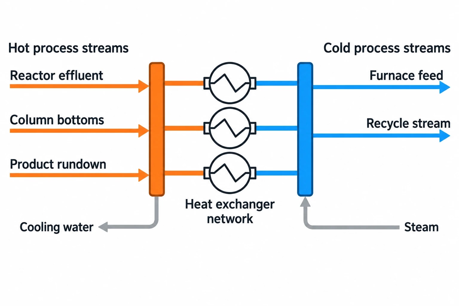
Chemical plants move large amounts of heat through reactions, separations, evaporation, drying, distillation and product cooling. A hot reactor effluent, column-bottoms stream or product rundown may reject heat while another stream needs steam or fired heat only metres away. The existing network often reflects plant expansions, grade changes, maintenance decisions and individual project scopes rather than a whole-process optimum.
A heat exchanger network, often shortened to HEN, is the collection of exchangers, heaters, coolers and utility connections that performs this work. Optimisation examines the network as one thermal system.
Established applications in refineries and petrochemicals
Ipieca identifies refineries and petrochemical facilities as established applications for pinch analysis because they contain complex exchanger networks and multiple hot and cold process streams. The approach also applies to chemical sites with distillation trains, solvent recovery, polymer finishing, reaction-quench systems, thermal-oil circuits and utility networks.
Common starting points include:
- A crude, feed or recycle stream entering a furnace at a lower temperature than available process heat could support.
- Excess cooling-water duty alongside high steam consumption.
- Heat exchangers bypassed after a process change.
- High fuel use after fouling has reduced exchanger performance.
- A production increase that has pushed existing exchangers beyond practical hydraulic or thermal limits.
- Waste-heat opportunities created by a plant expansion, new reactor or emissions-control system.
Energy targets and production targets can align
Higher recovered heat can reduce utility demand, but a project’s value can extend beyond energy. A revised exchanger sequence may relieve a furnace, improve feed-temperature stability, reduce cooling-tower loading or release steam capacity for another process. These effects need careful separation in the business case. A project should not claim the same benefit twice through reduced fuel, extra production and reduced utility constraints.

Identify where your plant is losing energy and quantify the savings potential — our audits map every heat source, sink, and waste stream in your facility.
What do 10-35% heat exchanger network savings mean?
The ISC3 benchmark concerns opportunities identified through pinch analysis and heat integration. It is not a universal site-wide energy-reduction commitment. A site with a well-integrated process may have a narrower gap to its target. A plant with separate heating and cooling demands, bypassed exchangers or major process changes may have a larger one.
Minimum Energy Requirement versus retrofit savings
Pinch analysis calculates a Minimum Energy Requirement, often called MER, for a defined set of streams and operating conditions. It is a thermodynamic target: the lowest external heating and cooling duties possible for the chosen process boundary and minimum temperature approach.
MER does not automatically define a retrofit project. It assumes suitable matches can be made without limits on equipment geometry, piping, pressure loss, control complexity or access. Brownfield engineering must convert the theoretical target into an achievable package.
| Target level | What it represents | Main use |
|---|---|---|
| Current energy use | Measured or reconciled fuel, steam, cooling and electrical demand | Establishes the baseline |
| MER target | Lowest utility demand permitted by the selected stream data and ΔTmin | Quantifies thermodynamic opportunity |
| Feasible retrofit target | Savings after area, hydraulics, fouling, control, safety, layout and shutdown constraints | Defines the technical project |
| Approved project target | Savings associated with selected capital measures and operating changes | Supports investment approval and measurement |
A credible study reports all four levels. This prevents the common error of presenting the gap between current performance and MER as an immediately available saving.
Selecting ΔTmin
The minimum temperature approach, ΔTmin, is a central decision in heat exchanger network optimisation. It is the smallest practical temperature difference permitted between hot and cold streams in the pinch model.
A lower ΔTmin permits more heat recovery but generally requires more exchanger area and can heighten fouling sensitivity. A larger ΔTmin reduces area requirements but raises heating and cooling utility demand. Ipieca notes that the choice reflects the trade-off between equipment and operating costs.
The right value depends on the services involved, exchanger type, stream cleanliness, control duty, utility temperature and project economics. A study should test more than one ΔTmin rather than selecting a convenient value. Sensitivity analysis shows whether a modest increase in recovered heat demands disproportionately costly equipment.
How pinch analysis sets a heat exchanger network optimisation target
Pinch analysis begins with a consistent process-data table. Each selected stream needs supply temperature, target temperature, mass flow, heat-capacity flowrate, phase change where relevant, pressure, composition, utility connection and operating case. The data must represent how the plant runs, including grade changes and rate limits.
Build the energy picture from validated plant data
Plant historian data, operating logs, laboratory results and P&IDs provide a starting point. Engineers should reconcile this information with site measurements before treating it as a design basis. An incorrect flowrate or assumed outlet temperature can create an attractive but unattainable heat-recovery target.
An on-site assessment can confirm:
- Stream temperatures across the normal production range.
- Differential pressure through existing exchangers.
- Steam flow and condensate return.
- Cooling-water supply and return temperatures.
- Bypass positions and control-valve behaviour.
- Fouling symptoms, including declining approach temperature or rising pressure loss.
- Actual heat duty during campaign transitions, start-up and turndown.
EnerTherm Engineering’s seven-step methodology connects this field work to the audit process: initial consultation, site assessment, targeted power and thermal measurements, data modelling, identification of Energy Conservation Measures, prioritisation and implementation support. Thermal imaging can support inspection of insulation, hot pipework and accessible exchanger connections, although it cannot replace process-side temperature and flow measurements.
Find the pinch and utility minimum
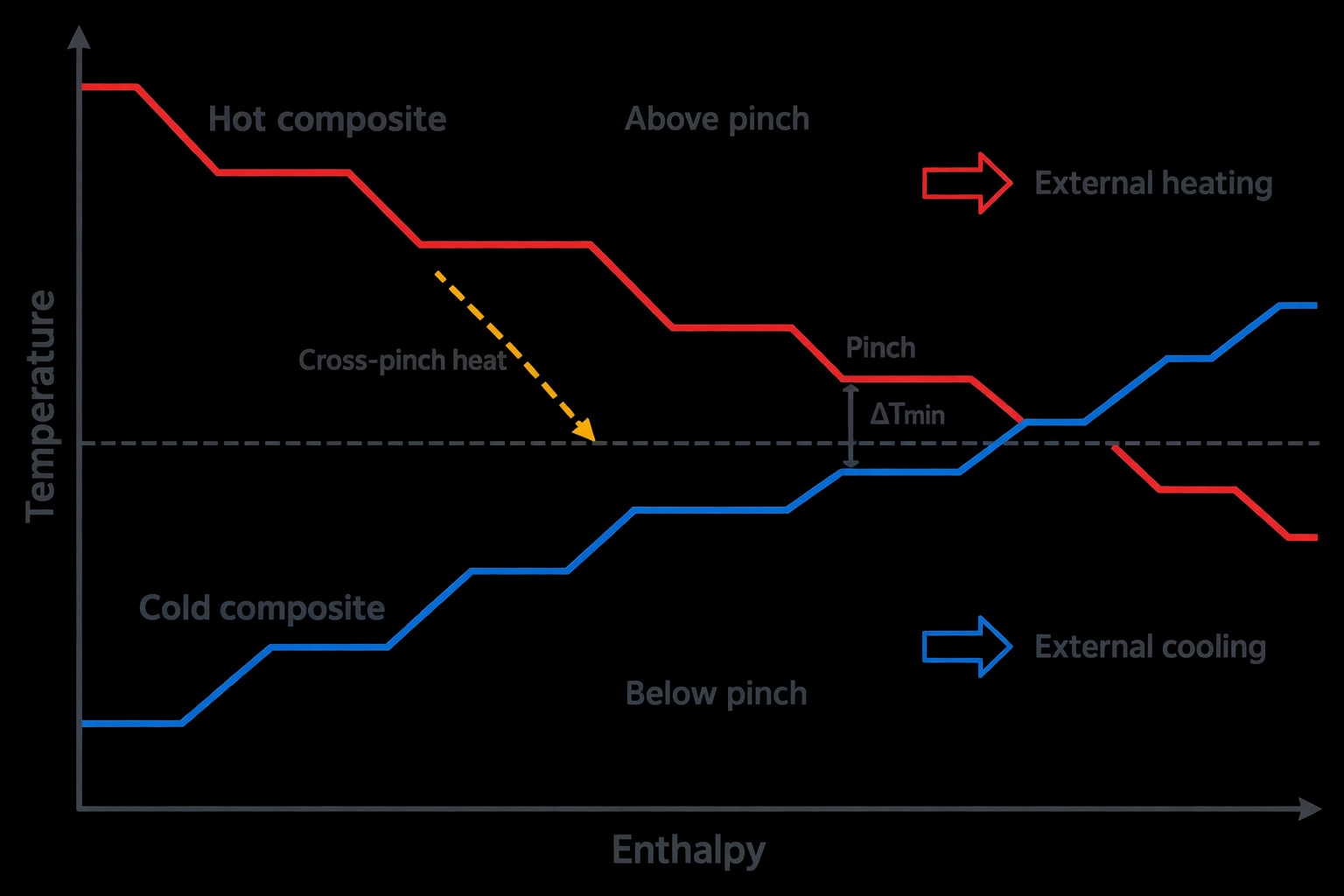
The pinch occurs where the hot and cold composite curves reach the selected ΔTmin. It divides the process into an above-pinch region requiring external heating and a below-pinch region requiring external cooling.
The resulting utility targets identify whether the site should focus on reducing fired-heater duty, steam use, cooling-water demand, refrigeration duty or a combination. They also show the penalty associated with existing cross-pinch heat transfer. Heat passed across the pinch increases external heating and cooling demand above the minimum.
The analysis should distinguish process streams from utilities. Heating boiler-feedwater or a thermal-oil circuit with process heat can be useful, but may deliver a different commercial result from direct process-to-process recovery. Utility constraints must be included before selecting the preferred retrofit.

Identify where your plant is losing energy and quantify the savings potential — our audits map every heat source, sink, and waste stream in your facility.
Screening heat exchanger retrofit options for plant reality
A network grid can generate many theoretical matches. Few survive detailed screening unchanged. The engineering task is to identify options that deliver worthwhile savings without creating an operating problem.
Exchanger area, hydraulics and fouling
Existing exchangers may have limited spare area. A warmer cold-side outlet can reduce temperature driving force elsewhere in the network. An exchanger that appears underused may also be constrained by pressure drop, nozzle loads, vibration risk or tube-side velocity.
Fouling changes the economic calculation. A close approach temperature can look attractive immediately after cleaning but become unachievable as deposits develop. Polymer, viscous, particulate, scaling and reactive services require particular care. The retrofit design should assess cleaning method, interval, isolation arrangements, bypass requirements and maintenance access.
Low velocity can reduce shear and increase fouling. Higher velocity can improve heat transfer but add pressure loss and pumping demand. These trade-offs should be quantified for each candidate rather than assumed from nameplate data.
Controllability and operating flexibility
A heat-recovery match creates a thermal dependency between two process streams. That dependency must remain stable through grade changes, rate changes, start-up, shutdown and upset conditions.
A new exchanger can alter the response of a temperature-control loop, restrict a cooler’s ability to meet product specification or transfer process disturbances between units. Ipieca advises that ideal pinch designs need modification to meet operability, flexibility and control requirements.
Control screening should consider:
- Whether the hot stream remains available when the cold stream needs heat.
- The consequence of one stream’s trip or reduced flow.
- Temperature-control valve authority after the modification.
- Minimum and maximum production rates.
- Product-quality limits and downstream temperature constraints.
- Required bypasses, isolation valves and relief implications.
- Whether dynamic simulation or a control review is justified.
Layout, piping and shutdown constraints
Distance between streams, pipe-rack congestion, structural steel, access routes and exchanger location can determine project viability. Long hot-oil or process lines also lose heat and add pressure drop. A modest energy target with short, accessible pipework can outperform a larger theoretical target requiring major civil works and a long outage.
Turnaround scope matters. Many retrofit measures require tie-ins, exchanger-bundle changes or new pipework that cannot be installed during normal production. The project schedule should identify the earliest realistic shutdown opportunity before the financial case is finalised.
UK safety and regulatory requirements for heat exchanger modifications
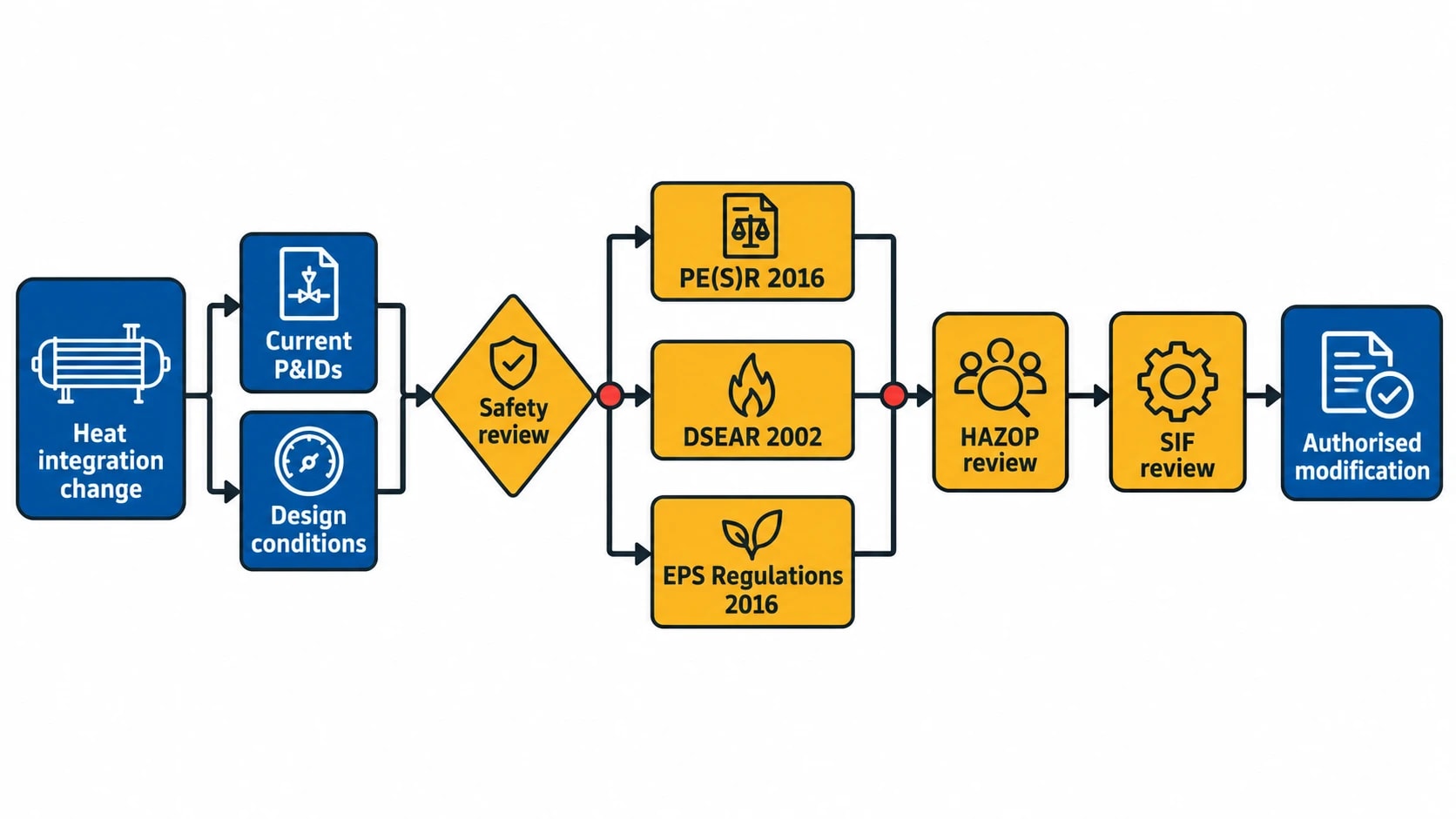
Heat exchanger network optimisation changes process temperatures, pressures, inventories and interfaces. Safety review must run alongside energy analysis from the first option-screening stage.
Pressure equipment and hazardous areas
The Pressure Equipment (Safety) Regulations 2016, SI 2016/1105, apply where new pressure equipment or assemblies are supplied within their scope. The design authority should establish the applicable conformity and technical-documentation requirements for each new or materially altered item before procurement.
For plant handling dangerous substances, the Dangerous Substances and Explosive Atmospheres Regulations 2002, SI 2002/2776, require risk assessment and control of risks from dangerous substances and explosive atmospheres. New pipework, instruments, isolation arrangements or exchanger packages can alter hazardous-area assumptions, leak scenarios and ignition-source controls.
Where a modified system sits in a classified hazardous area, the Equipment and Protective Systems Intended for Use in Potentially Explosive Atmospheres Regulations 2016, SI 2016/1107, apply to equipment and protective systems supplied for use in potentially explosive atmospheres. The engineering team should verify equipment selection against the hazardous-area classification and the project’s ignition-risk assessment.
Management of change is part of the energy project
The Health and Safety Executive advises that plant modifications should be subject to formal management procedures and a traceable safety, engineering and technical review. A heat-integration project therefore needs current P&IDs, line lists, design conditions, relief reviews, hazardous-area information and operating procedures.
HAZOP scope should reflect the hazard and scale of the change. Possible deviations include hot-stream flow with no cold-side flow, a cold stream entering a hotter-than-designed downstream vessel, tube-leak contamination between incompatible fluids, blocked-in thermal expansion and loss of cooling capacity during bypass operation.
For safety-instrumented functions, engineers must assess whether revised temperatures, flows or response times affect allocated Safety Integrity Level requirements. Energy performance cannot justify reduced process protection.
Turning pinch targets into a ranked Energy Conservation Measure plan
The preferred heat exchanger network optimisation programme usually combines operational corrections with capital retrofit measures. This improves the investment sequence and can deliver savings before a major turnaround.
Prioritise measures by value and implementation route
A practical register separates opportunities by intervention type.
| Measure type | Typical example | Main decision factors |
|---|---|---|
| Operational | Close an unnecessary bypass or restore an intended exchanger sequence | Process stability, procedures, instrumentation |
| Maintenance | Clean or repair a fouled exchanger | Duty recovery, cleaning interval, production impact |
| Minor modification | Add a bypass control arrangement or repipe a short connection | Tie-in complexity, control review, outage duration |
| Capital retrofit | Install a new exchanger or add area to an existing train | NPV, payback, pressure design, plot space, turnaround |
| Network redesign | Reorder several exchangers and alter utility placement | Whole-plant operability, safety review, capital scope |
Each Energy Conservation Measure should state the baseline duty, estimated utility saving, required investment, operating assumptions, CO₂ impact, production interaction, implementation window and measurement plan. Net present value and payback should include exchanger maintenance, pumping energy, additional instrumentation, civil works, insulation, design assurance and lost-production exposure during installation.
Measure and verify the realised savings
Fuel and steam savings cannot be measured directly because they represent avoided consumption. They require a defined baseline and measured post-installation performance under comparable conditions.
The International Performance Measurement and Verification Protocol, IPMVP Core Concepts 2022, provides a useful framework. A heat exchanger retrofit may use a retrofit-isolation boundary around the affected utility and process equipment, or a wider boundary where multiple measures interact.
An M&V plan should define:
- The utility meters and process measurements used.
- The baseline and reporting periods.
- Production rate, grade, ambient conditions and feed properties requiring adjustment.
- Data-quality checks and calibration responsibilities.
- Expected fouling behaviour and any post-cleaning performance allowance.
- Reporting frequency and acceptance criteria.
This approach gives plant managers a defensible record of savings and exposes performance drift early. It also keeps the HEN model useful after the project closes. New operating data can identify lost heat recovery, exchanger fouling and fresh debottlenecking opportunities.
This article reflects the independent analysis and editorial opinion of EnerTherm Engineering. Product names, trademarks, and brands mentioned belong to their respective owners. EnerTherm Engineering is not affiliated with, endorsed by, or a licensee of any third-party software or product mentioned unless explicitly stated.

Managing Director — EnerTherm Engineering
Dr. François Pierrel is Managing Director of EnerTherm Engineering with over two decades of expertise in thermal design, heat transfer, and industrial energy optimisation. He holds a PhD in Heat Transfer from Cranfield University and a Post-Doctorate from Heriot-Watt University.
