Pinch Analysis for Heat Exchanger Networks: 10-35% Savings
A 10-35% screening benchmark for heat-recovery opportunities before retrofit design.
Pinch analysis for heat exchanger networks is a thermodynamic method that establishes the minimum heating and cooling utilities a chemical process needs after maximum feasible internal heat recovery. ISC3 reports that pinch and heat-integration applications in chemicals, refining, pulp and paper can typically identify 10-35% energy-saving opportunities. This is a screening benchmark, not a project guarantee, but it gives UK chemical manufacturers a credible reason to test established heat exchanger networks against a whole-process energy target.
The evidence often sits in the utility balance. A hot product stream is cooled by cooling water or air while another stream receives steam, thermal oil or fired-heater duty. Each heat exchanger may operate as intended. The combined network may still reject heat at one temperature and buy heat at another.
Pinch analysis quantifies that gap before a project team commits to new heat-exchanger area, pipework, controls or shutdown scope. It separates the theoretical minimum utility demand from the practical retrofit that can deliver part of it.
Why pinch analysis matters for heat exchanger networks
Chemical plants accumulate heat-recovery gaps
Heat exchanger networks rarely remain in their original form. Process units gain capacity, product grades change, spare exchangers enter service, and turnaround constraints shape modifications. These changes can leave a network with utility use that made sense for an earlier operating case.
Common streams in a chemical pinch study include reactor feeds, distillation feeds and bottoms, solvent-recovery streams, product rundown, dryer exhaust, condensate, boiler feedwater, thermal-oil loops and wash streams. Polymer and speciality-chemical plants may also have viscous, solids-bearing or crystallising duties that need close review.
A pinch study looks across the network rather than treating each heat exchanger as an isolated item. It asks three linked questions:
- Which hot streams have recoverable heat at a useful temperature?
- Which cold streams can receive that heat without harming process performance?
- What utility demand remains once suitable internal recovery has been targeted?
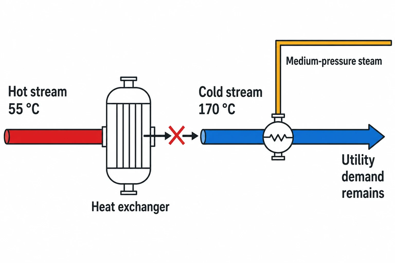
A large heat duty is not automatically valuable. Heat released at 55 °C cannot displace medium-pressure steam heating a stream that must reach 170 °C. Temperature level, not duty alone, determines the quality of the opportunity.
The 10-35% figure needs disciplined use
The 10-35% range applies to opportunities identified in multiple industrial sectors. It should inform early screening, not appear as a fixed saving in a capital request.
The available saving at a particular site depends on the existing degree of integration, plant throughput, stream temperatures, exchanger condition, utility prices, operating constraints and the age of the network. A recently modernised continuous plant can already sit close to its thermodynamic target. A network expanded through several brownfield projects may show a larger gap.
A sound project statement defines three values separately:
- Current hot and cold utility consumption for a specified operating case.
- The maximum-energy-recovery target at a selected minimum temperature approach.
- The forecast utility reduction from the practical retrofit scope.
That distinction prevents a theoretical target being presented as delivered plant performance.

Identify where your plant is losing energy and quantify the savings potential — our audits map every heat source, sink, and waste stream in your facility.
Building the stream data behind pinch analysis
Define a representative operating case
The stream table is the foundation of pinch analysis for heat exchanger networks. It should describe a stable, commercially meaningful operating condition rather than an annual average that masks campaigns, grade changes or throughput swings.
Each process stream needs a supply temperature, target temperature, flowrate or heat-capacity flowrate, pressure, physical state and relevant operating range. Engineers should record phase changes explicitly. Condensing vapour, boiling liquid, evaporation and crystallisation can carry substantial duties at nearly constant temperature.
| Stream-data item | Why it affects the pinch target or retrofit |
|---|---|
| Supply and target temperatures | Defines where heat is available or required |
| Heat-capacity flowrate | Determines sensible heating or cooling duty |
| Phase-change temperature and latent heat | Captures condensing, boiling and evaporation duties |
| Operating pressure | Affects phase behaviour and feasible utility levels |
| Flowrate and campaign range | Tests whether a match remains useful across production cases |
| Fouling condition and cleaning record | Distinguishes network design issues from lost exchanger performance |
| Allowable pressure drop | Identifies matches that could create pumping or compressor penalties |
| Process compatibility | Screens process-to-process matches with unacceptable contamination consequences |
Process flow diagrams, piping and instrumentation diagrams, exchanger datasheets, historian trends, laboratory information and utility meters provide the starting point. Each value needs a technical check. A poorly mixed temperature measurement, inferred steam flow or inaccurate flowmeter can distort the target and send the study towards the wrong heat-exchanger match.
A reconciled heat and mass balance provides a useful test. If a stream’s reported temperature drop, flowrate and physical properties do not align with its known exchanger duty, the team should resolve the discrepancy before constructing composite curves.
Treat fouling as operating data, not an afterthought
Existing heat exchangers do not operate at clean-design conditions. Organic deposits, polymer films, scale, solids, corrosion products and bypass leakage can reduce thermal performance. Operators may compensate with higher steam flow, lower throughput, more cooling water or altered setpoints.
A pinch study should identify whether stream data represent current fouled operation, post-cleaning performance or design intent. These are different cases. Exchanger cleaning can recover heat at low capital cost, while a new exchanger project should use realistic fouling allowances and cleaning requirements.
This distinction also protects the investment case. A retrofit cannot claim the same steam saving already assigned to cleaning, bypass correction or an exchanger maintenance programme.
How maximum-energy-recovery targeting works
Composite curves find the pinch
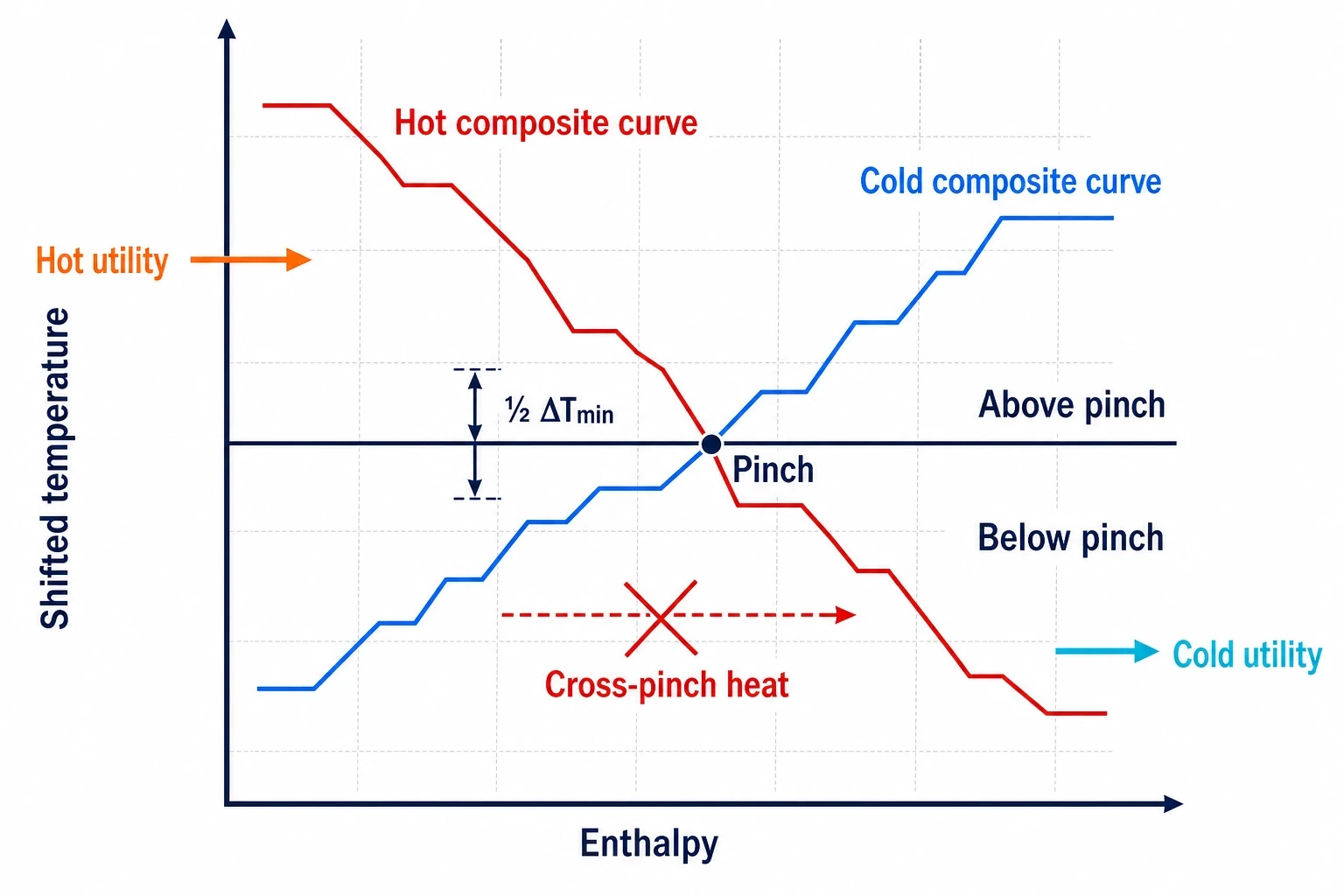
Pinch analysis combines process streams into two temperature-enthalpy relationships. The hot composite curve represents all streams that must be cooled. The cold composite curve represents all streams that must be heated.
Engineers shift the hot and cold stream temperatures by half of the chosen minimum temperature difference, ΔTmin, then use the problem table algorithm or composite curves to identify the closest approach. That point is the pinch.
The pinch is a thermodynamic constraint, not a physical valve, exchanger or line on the plant. It identifies the limiting temperature region for heat recovery at the selected ΔTmin. The analysis then establishes:
- Minimum hot-utility demand.
- Minimum cold-utility demand.
- Maximum feasible process-to-process heat recovery.
- Temperature levels where utilities may be most appropriate.
A grand composite curve can help teams examine the temperature level of remaining heat deficit and surplus. That supports early decisions on whether steam pressure, thermal oil, fired heating, cooling water, air cooling or refrigeration is a plausible fit.
ΔTmin sets an energy and capital trade-off
A smaller ΔTmin permits greater heat recovery because streams can approach more closely. It commonly requires more heat-exchanger area and can increase capital expenditure, fouling sensitivity and control difficulty. A larger ΔTmin reduces heat-exchanger area but increases steam, fuel and cooling demand.
There is no universal ΔTmin for chemical plants. The appropriate value depends on energy costs, cooling costs, exchanger type, fouling behaviour, plot constraints, process temperatures and the economic life of the asset.
Project teams should test several values rather than selecting a convenient temperature approach from a previous design. The selected value should reflect the cost of delivered utility, not only the price of fuel at the boiler house. For example, a marginal cooling-water reduction may have little value until it avoids a cooling-system constraint, whereas a marginal reduction in high-pressure steam can have a material fuel and emissions benefit.
Pinch rules show where utilities create penalties
At the selected ΔTmin, maximum-energy-recovery targeting follows three established rules:
- Do not add external cooling above the pinch.
- Do not add external heating below the pinch.
- Do not transfer process heat across the pinch.
A cross-pinch match increases both hot-utility and cold-utility demand above the thermodynamic minimum. The resulting utility penalty is visible in the target calculation.
Operating plants may retain such arrangements for valid reasons. A cooler may protect a product specification, a trim heater may manage start-up, or a process unit may require independent control. Pinch analysis does not remove those requirements. It quantifies their energy consequence, enabling a process and utilities team to compare that cost with the operating benefit.

Identify where your plant is losing energy and quantify the savings potential — our audits map every heat source, sink, and waste stream in your facility.
Heat exchanger network optimisation in brownfield plants
Screen matches before drawing a retrofit
Composite curves establish the target. Heat exchanger network optimisation turns that target into feasible matches between real streams.
A candidate match must supply enough temperature driving force across the relevant operating envelope. It must also fit the available heat-exchanger technology, metallurgy, pressure drop, fouling characteristics and process-control requirements. A match that works at maximum throughput may fail during a low-rate campaign. A match with an attractive thermal target can create an unacceptable pressure loss or make a difficult stream harder to clean.
A practical screening review should assess:
- Heat duty and terminal temperature differences at normal, minimum and maximum rates.
- Exchanger area, expected fouling resistance and maintenance access.
- Pressure drop, pump or compressor margin and control-valve authority.
- Fluid compatibility and the consequence of an internal leak.
- Plot space, pipe routing, structural supports and tie-in points.
- Isolation, drainage, venting, cleaning and turnaround access.
- Start-up, shutdown, grade change and upset-control requirements.
- Interactions with boilers, fired heaters, cooling water and refrigeration systems.
The strongest measures often combine thermal merit with a manageable installation scope. A rearranged exchanger train, corrected bypass strategy, lower steam-pressure level, additional shell-and-tube exchanger or removal of an unnecessary cooler can all be valid outcomes.
Preserve controllability and product quality
A new process-to-process exchanger couples streams that may previously have been controlled independently. That can change the response of feed-temperature loops, product coolers and utility trim systems.
Design teams should establish the operating philosophy before detailed mechanical design. It should define control targets, bypass positions, minimum-flow conditions, start-up sequence, cleaning isolation and the conditions under which a trim heater or cooler remains in service.
This is particularly important for batch and campaign plants. A heat match can be highly effective during one reaction or distillation stage yet offer little value when the next product grade runs at different flowrates or temperatures. Multi-period pinch analysis gives a more realistic view where those operating cases materially alter the heat balance.
A pinch-specific workflow for energy audits
Move from validated data to utility targets
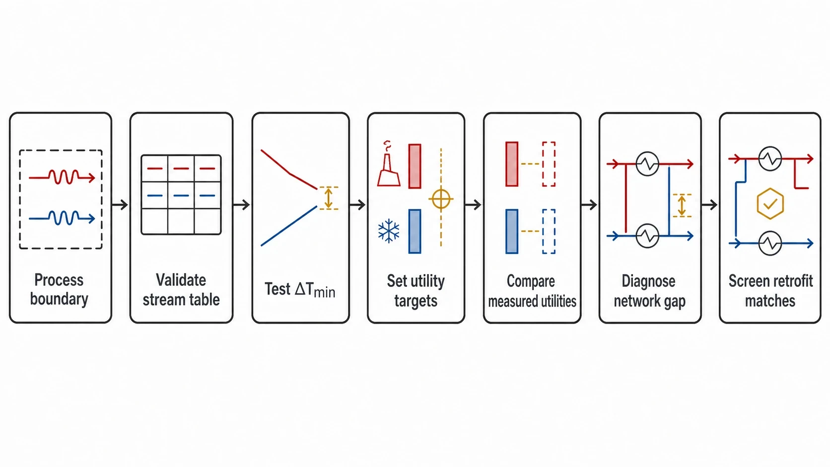
An energy audit for chemical processing can use pinch analysis to identify recoverable process heat. The workflow should remain focused on the heat exchanger network and its utility consequences.
- Define the process boundary, included utilities, operating cases and required decision.
- Build and validate the stream table using plant data, field checks and reconciled balances.
- Select and test ΔTmin values that reflect energy cost, exchanger economics and operating constraints.
- Apply the problem table algorithm and composite curves to establish minimum utility targets.
- Compare the targets with current measured steam, fuel, cooling-water, air-cooling or refrigeration demand.
- Identify existing cross-pinch transfer, utility placement and exchanger duties that explain the gap.
- Screen retrofit matches for thermal feasibility, pressure drop, fouling, controllability, installation scope and expected return.
This process makes the audit trail clear. A heat-recovery project can show where the target came from, which practical constraints narrowed the options and why a selected measure offers the best delivered value.
Rank measures by practical return
A heat-recovery target does not rank capital projects by itself. Each Energy Conservation Measure needs a defined scope, utility reduction, capital estimate, shutdown requirement, maintenance effect and production impact.
Simple payback is useful for initial comparison, but it can favour short-life changes over measures that provide a larger long-term return. Net present value gives a more complete view when energy prices, production assumptions, major maintenance and project life are significant.
Project teams should account for measure interactions. Reducing steam demand through process heat recovery can alter boiler load, condensate availability and fired-heater operation. Reducing cooling duty can affect cooling-water return temperature or refrigeration loading. A common energy balance avoids double-counting across a portfolio.
Measuring savings after heat-exchanger-network changes
Set the baseline before installation
The pinch target measures opportunity. Measurement and verification establishes what the installed project delivered.
For a distinct exchanger retrofit, a retrofit-isolation approach can meter the affected steam, fuel, cooling or electricity use alongside the stream temperatures and flows that determine recovered duty. For several interacting measures across a process unit, a boundary-level method may be more appropriate, using utility meters and a baseline model.
The measurement plan should state the boundary, baseline period, meter locations, data intervals, reporting period and data-quality checks. It should also record the independent variables that influence utility consumption. In chemical processes these commonly include production rate, grade mix, feed temperature, operating pressure, ambient conditions, batch cycle and cooling-water temperature.
Calculate adjusted, not superficial, savings
An IPMVP Core Concepts 2022 approach compares post-project energy use with the energy the baseline would have used under reporting-period conditions. The method avoids treating a production decline, cooler ambient weather or a feedstock change as a heat-recovery saving.
The basic calculation is:
Avoided energy consumption=adjusted baseline energy−reporting-period energyAdjusted baseline energy is the baseline utility use modelled at reporting-period production and operating conditions. Reporting-period energy is the measured utility use after the retrofit. The plan should also identify non-routine changes, such as a new production line, major maintenance event or permanent operating change, and define how they will be treated.
Routine monitoring confirms whether recovery persists. Rising steam use at comparable production may indicate exchanger fouling, a bypass opening, control-valve drift, changed feed temperature or a shift in product mix.
This article reflects the independent analysis and editorial opinion of EnerTherm Engineering. Product names, trademarks, and brands mentioned belong to their respective owners. EnerTherm Engineering is not affiliated with, endorsed by, or a licensee of any third-party software or product mentioned unless explicitly stated.

Managing Director — EnerTherm Engineering
Dr. François Pierrel is Managing Director of EnerTherm Engineering with over two decades of expertise in thermal design, heat transfer, and industrial energy optimisation. He holds a PhD in Heat Transfer from Cranfield University and a Post-Doctorate from Heriot-Watt University.
