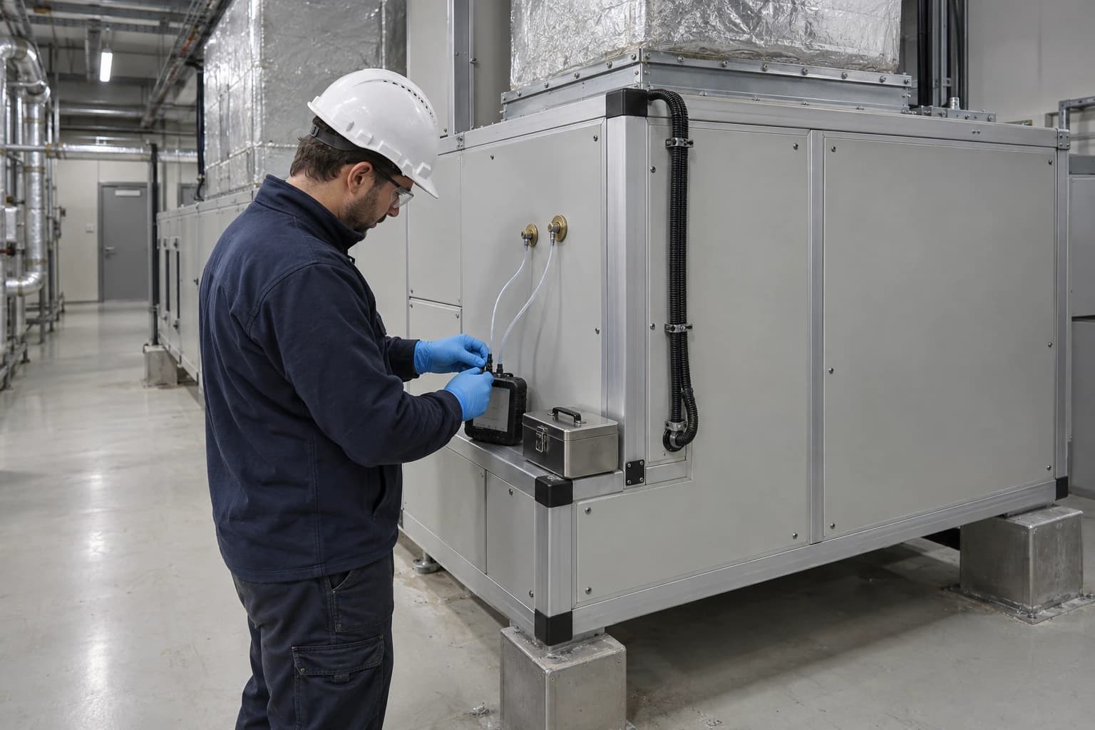
Why Cleanroom HVAC Dominates a Pharmaceutical Factory Audit
Cleanroom HVAC can account for 50-75% of electrical use, subject to GMP controls.
A cleanroom HVAC system is the heating, ventilation and air-conditioning plant that controls air cleanliness, temperature, humidity, airflow and pressure in a classified pharmaceutical space. Research on pharmaceutical cleanrooms reports that HVAC commonly represents 50% to 75% of cleanroom electrical energy use, driven by high air-change rates, filtration resistance and tightly controlled environmental conditions.
That concentration of load changes the priorities of an energy audit pharmaceutical factory programme. Boilers, chillers, compressed air and process equipment all merit examination, yet cleanroom HVAC often sets the scale of the opportunity and the operational risk. A small adjustment to an air handling unit can affect fan power, chilled-water demand, heating demand, humidity control, room pressure and particle-control performance at the same time.
For facilities managers, energy managers and engineering directors, the task is not to reduce ventilation indiscriminately. It is to establish which airflows, pressure differences and environmental conditions are necessary for each operating state, then remove energy consumed above that verified requirement.
Why cleanroom HVAC leads the energy audit pharmaceutical factory
High airflow creates a large, continuous electrical load
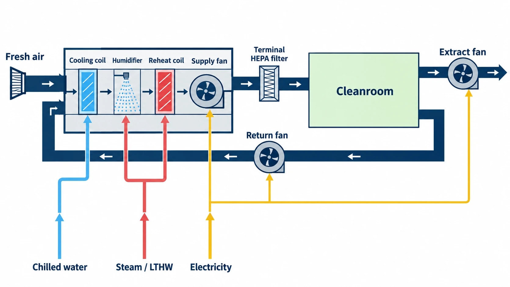
A pharmaceutical cleanroom consumes energy through more than its supply fan. Return and extract fans, terminal filters, fresh-air conditioning, cooling coils, reheating, humidification, dehumidification, pumps and controls all sit within the HVAC energy boundary.
High-efficiency particulate air filters add pressure drop. As filters load, fan duty can rise. Long duct routes, poorly arranged dampers, restrictive coils and incorrect fan selection create further resistance. A site may therefore operate several large fans around the clock to move air required only during production, set-up, cleaning or recovery.
The fan energy penalty deserves early attention because airflow and fan power have a strongly non-linear relationship. A validated airflow reduction during an at-rest period can therefore produce a material electricity saving, provided the room can recover to its required state before production resumes.
Cleanrooms consume energy in several utility systems
The electrical meter at the air handling unit rarely captures the full cost of a classified area. An energy audit pharmaceutical factory exercise should trace the HVAC load into the site utilities that serve it:
- Electrical energy for supply, return and extract fans
- Chilled water for sensible cooling and latent-load removal
- Steam, low-temperature hot water or electric heat for reheating and humidification
- Pumping energy for chilled-water, condenser-water and heating circuits
- Compressed air where pneumatic dampers, valves or controls depend on it
- Boiler fuel and refrigeration plant energy supporting air treatment
This broader view matters where an air handling unit simultaneously cools and reheats air. A site can achieve acceptable room conditions while paying for unnecessary cooling, dehumidification and reheat.
Energy intensity is shaped by GMP requirements
Cleanroom HVAC maintains the contamination-control conditions needed to manufacture medicines safely and consistently. That duty explains why a pharmaceutical or sterile-products facility cannot treat an air-change figure as a simple energy setting.
EU GMP Annex 1 requires a contamination control strategy and sets expectations for airflow, pressure differentials and environmental monitoring in sterile medicinal product manufacture. Airflow direction must protect the critical zone. Pressure cascades must prevent contamination transfer between areas. Environmental controls require qualification and ongoing monitoring.
HVAC therefore combines high energy consumption with direct product-quality consequences. A proposed energy measure must preserve the validated state and create evidence that it has done so.

Pinch analysis identifies the thermodynamic minimum energy requirement of your process — then designs the heat exchanger network to achieve it.
What the audit team should measure before changing cleanroom operation
Build a credible load profile
An effective energy audit pharmaceutical factory assessment starts with 12 months of verifiable utility data, then narrows into the cleanroom systems that drive consumption. Half-hourly electricity data, gas consumption, chilled-water production, boiler output and production calendars establish the initial profile.
The next step is sub-metering and operating evidence. A fan that appears to run continuously may serve rooms with distinct modes: production, cleaning, set-up, idle, maintenance and at-rest. Aggregated monthly energy data conceals these differences.
The audit should compare plant operation with room occupancy, batch schedules, door activity, pressure alarms and temperature and humidity trends. It should also identify plant that continues at full duty during planned production gaps.
Measure the air system, not just the fan motor
A fan kW reading is useful, but it does not diagnose why that power is required. The audit should collect enough information to link energy use with airflow, resistance and room performance.
| Audit target | Evidence to collect | Energy relevance | GMP consideration |
|---|---|---|---|
| Supply and extract fans | Electrical power, speed, airflow, static pressure and operating hours | Identifies constant-volume operation and excessive system resistance | Airflow pattern and room recovery must remain qualified |
| Terminal and central filters | Differential pressure, filter age, installation condition and change records | Shows pressure-drop burden and potential bypass issues | Filter integrity and classification performance remain essential |
| Room pressure cascade | Differential-pressure trends, alarms, door-opening events and room relationships | Reveals unnecessary pressure setpoints and leakage | Direction of airflow between areas must protect the process |
| Temperature and humidity control | Supply and return air conditions, coil duty, reheat demand and room trends | Exposes simultaneous cooling and heating | Setpoints must meet product, process and operator requirements |
| Fresh-air treatment | Outdoor-air volume, treatment coil duty and extract rate | Quantifies heating, cooling and dehumidification load | Outdoor-air changes need contamination-control assessment |
| Chilled-water and heating circuits | Flow, temperatures, pump power and control-valve position | Locates poor coil control and low distribution efficiency | Changes must retain environmental control under worst-case conditions |
The site team should inspect the plant while it operates. Trend data can reveal a control fault, but a walkthrough often finds dampers fixed in one position, leaking doors, failed actuators, coils with poor heat transfer or local extracts that no longer match the process.
Establish a baseline by room state
A cleanroom should not be treated as a single annual energy figure. Separate energy and performance baselines are needed for each defined operating state.
Production and critical interventions may require full airflow. At-rest operation may permit lower, validated airflow where the contamination control strategy allows it. The same approach can apply to adjoining support rooms, change areas and transfer corridors, subject to their relationship within the pressure cascade.
The baseline should include:
- Room classification and GMP grade.
- The permitted operating states and the formal trigger for each state.
- Airflow, pressure, temperature and humidity requirements in each state.
- Recovery time after a change in airflow or occupancy.
- Particle, microbiological and environmental monitoring requirements.
- The energy use of fans, cooling, heating and pumping for each state.
This produces a defensible basis for prioritising savings measures and prevents later disputes over whether an energy reduction changed a validated condition.
How GMP and cleanroom standards shape the audit
Use BS EN ISO 14644-16:2019 as the energy framework
BS EN ISO 14644-16:2019 provides guidance on optimising energy use in new and existing cleanrooms and separative devices while maintaining required cleanroom performance. Energy performance can be benchmarked and improved, yet the cleanroom must continue to meet its specified performance level.
That balance should govern the audit report. Each recommendation needs a defined energy mechanism, operating boundary, GMP impact, test protocol and monitoring evidence for implementation. A proposal to lower fan speed without that structure is incomplete.
The standard supports a whole-system view. Fan energy depends on airflow and total pressure loss, while thermal energy depends on fresh-air treatment, recirculation, heat gains, humidity load, coil control and heat-recovery opportunities.
Protect the pressure cascade and clean-up performance
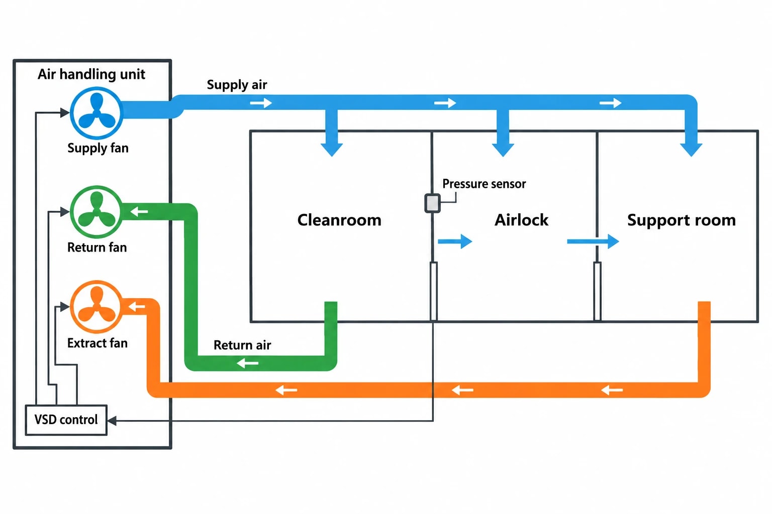
Pressure differentials are part of the contamination-control system. An audit should map the intended direction of airflow between rooms, including how the system behaves when doors open, personnel move between spaces or an air handling unit trips.
A reduced airflow setpoint can alter room pressurisation. Extract flow that stays fixed while supply flow falls can reverse a pressure relationship. Variable-speed control should therefore coordinate supply, return and extract fans, with clear response actions for alarms and failed sensors.
Clean-up performance also needs testing. The time required for a room to return to its required condition after occupancy, intervention or airflow reduction may determine whether an at-rest strategy is viable. The site should use its approved change-control and qualification process before changing normal operating parameters.
Treat validation as part of the project scope
Energy work in a GMP facility carries a documentation burden because the HVAC system is linked to product protection. The audit must allow for engineering assessment, quality review, risk assessment, commissioning, qualification and updated standard operating procedures.
This does not prevent energy improvement. It ensures that a changed setpoint, control sequence or operating schedule has traceable acceptance criteria and can demonstrate its effect on energy performance and the controlled environment.

Pinch analysis identifies the thermodynamic minimum energy requirement of your process — then designs the heat exchanger network to achieve it.
Cleanroom HVAC measures that deserve early investigation
Reduce airflow only in defined, validated states
Variable air volume and airflow turndown can reduce fan power during at-rest periods. Research on cleanroom ventilation has examined occupancy-based operation, particle-based control and improved airflow patterns as routes to lower ventilation energy.
The practical question is whether a specific room can move safely into a lower-airflow state, how quickly it must return to full operation, and which performance tests demonstrate compliance. An audit should avoid applying one turndown percentage across a site. A sterile filling room, a materials airlock and a non-sterile support area carry different risks.
Remove unnecessary pressure losses
Filter differential pressure, coil cleanliness, duct restrictions and poorly selected terminal devices can force fans to operate at elevated power. The audit should distinguish between required filtration duty and avoidable resistance.
Potential actions include reviewing filter-change criteria, repairing air leakage, correcting duct obstructions, resetting variable-speed drives and confirming that dampers operate as designed. Each action needs post-work airflow balance and performance verification.
Eliminate simultaneous heating and cooling
Pharmaceutical air handling often requires cooling and dehumidification followed by reheating to achieve the supply-air condition. Some reheat is inherent to a required humidity-control duty. Excess reheat can result from low supply-air temperatures, poorly tuned control valves, excessive outdoor air, unstable humidity control or leaking heating valves.
Trend data should examine cooling-valve and heating-valve positions alongside supply-air temperature and humidity. Persistent simultaneous demand identifies a specific investigation point. The remedy may be a control-sequence change, sensor calibration, valve repair or revised coil-control limits.
Match plant schedules to the approved production programme
Scheduled operation can be an overlooked source of savings. Air handling units may start earlier than needed, run through extended breaks or remain at production duty after a batch finishes. The approved manufacturing programme and room-status controls should inform the HVAC schedule.
The audit should verify that schedule changes preserve room recovery time, pressure relationships and pre-use checks. A shorter run-time proposal must include responsibility for confirming that the controlled environment is ready before production begins.
Where Pinch Analysis supports pharmaceutical HVAC efficiency
Map the thermal loads around the air system
Pinch Analysis has a focused role in a pharmaceutical factory energy audit. It examines where heat is required, where heat is rejected, and whether thermal loads can be matched more effectively before additional utility capacity is considered.
For cleanroom HVAC, the starting point is the air treatment train and its connected utilities. Cooling coils remove sensible and latent heat. Reheat coils restore supply-air temperature. Chilled-water systems reject heat at condensers. Boiler or low-temperature hot-water systems provide heat to coils, humidifiers and building loads.
A thermal study can identify whether a facility rejects useful heat while burning fuel or consuming electricity to reheat air elsewhere. It can also reveal opportunities to use heat-pump output, recover heat from suitable non-contaminated exhaust streams, or improve the temperature levels at which heating and cooling utilities operate.
Keep contamination control at the centre of heat recovery decisions
Heat recovery requires a rigorous contamination-risk assessment. The location of the exchanger, air-stream separation, leakage risk, cleanability and failure modes all matter. Process exhaust and hazardous or potent-compound exhaust may be unsuitable for direct heat recovery into supply air.
Indirect systems, such as run-around coils with a sealed intermediate circuit, can offer a different risk profile. Their suitability still depends on the process, containment strategy and engineering assessment. Heat recovery should be evaluated as a cleanroom and GMP project, not as a generic building-services upgrade.
Prioritise measures in the right order
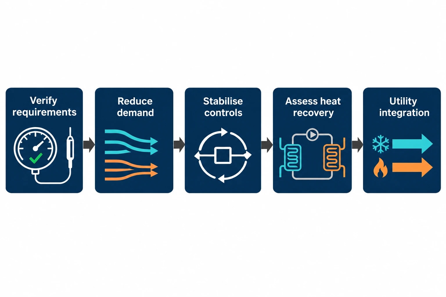
A sensible programme addresses avoidable demand before adding recovery equipment. Excess airflow, blocked filters, poor control tuning and unnecessary reheat can inflate the apparent value of a heat-recovery project.
The strongest sequence is to verify room requirements, reduce avoidable air and thermal demand, stabilise controls, then assess heat recovery and utility integration against the residual load. This gives Pinch Analysis a more accurate representation of the factory’s thermal requirement.
ESOS Phase 4 and the evidence a pharmaceutical site needs
Prepare early for the 2027 deadline
The UK Energy Savings Opportunity Scheme requires qualifying large undertakings to submit a Phase 4 notification of compliance by 5 December 2027. Qualifying organisations are assessed against the large-undertaking definition on 31 December 2026.
An ESOS-compliant audit must use verifiable energy-consumption data measured over a 12-month period, analyse energy use and energy efficiency, identify savings opportunities and include site visits. For a pharmaceutical facility, cleanroom HVAC should be supported by evidence rather than broad assumptions based on floor area.
Phase 4 also places stronger emphasis on reporting progress against action-plan commitments. A cleanroom HVAC project therefore benefits from a documented baseline, implementation record and measured post-project results.
Link the audit to continual energy management
ISO 50001:2018 provides a management-system framework for improving energy performance. In a pharmaceutical setting, it can connect the formal energy audit to engineering governance, including objectives, monitoring, corrective action, capital planning and management review.
For HVAC, useful energy-performance indicators may include fan energy by cleanroom operating hour, air handling unit energy by defined operating state, chilled-water energy per production campaign, or reheat demand against outdoor conditions. The indicator must account for production and cleanroom status, otherwise it can reward a reduction in output rather than genuine efficiency improvement.
This article reflects the independent analysis and editorial opinion of EnerTherm Engineering. Product names, trademarks, and brands mentioned belong to their respective owners. EnerTherm Engineering is not affiliated with, endorsed by, or a licensee of any third-party software or product mentioned unless explicitly stated.

Managing Director — EnerTherm Engineering
Dr. François Pierrel is Managing Director of EnerTherm Engineering with over two decades of expertise in thermal design, heat transfer, and industrial energy optimisation. He holds a PhD in Heat Transfer from Cranfield University and a Post-Doctorate from Heriot-Watt University.
