Automotive HVAC Energy Control Systems for Paint Shops
Average 19% energy cost reduction from coordinated HVAC and paint-shop controls.
Automotive HVAC energy control systems vary paint-shop ventilation, air treatment and extraction in line with production demand while maintaining the environmental conditions required for coating quality, VOC control and safe operation.
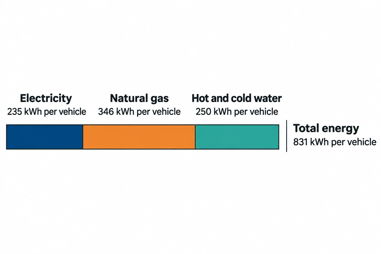
One reference configuration in the EU Surface Treatment Using Organic Solvents BREF recorded 831 kWh per vehicle for a paint shop: 235 kWh of electricity, 346 kWh of natural gas and 250 kWh of hot and cold water. That figure is not a universal target for a UK plant. It does, however, show why spray booths, make-up air units, ovens and VOC abatement should be managed as a connected system rather than as isolated utility loads.
Paint shops need high air volumes. Supply air must be filtered, heated, cooled and, where necessary, humidified. Extract systems maintain the required airflow direction and carry paint mist and VOC-containing air towards separation and abatement equipment. These duties change with vehicle throughput, body gaps, shift patterns, ambient weather, maintenance and planned downtime.
Demand-based HVAC control defines safe operating modes, then adjusts airflow and thermal output to suit the actual state of the paint process. It can reduce unnecessary fan electricity and outside-air conditioning without relaxing approved paint-application conditions.
Why automotive HVAC energy control matters in paint shops
The 2020 Surface Treatment Using Organic Solvents BREF reports a yearly BAT-associated energy-performance range of 0.5 to 1.3 MWh per passenger vehicle coated. Plant design, coating chemistry, climate, production utilisation and the number of drying stages all affect the result.
The BREF identifies local climatic conditions as a contributor to paint-shop energy demand. Heating, cooling and dehumidifying process air can account for a substantial share of consumption, particularly where large quantities of outside air pass through booths and make-up air units.
The production-normalised energy context
The BREF reference configuration illustrates why utility data should remain separated by energy source.
| Energy input | Reference configuration consumption |
|---|---|
| Electricity | 235 kWh per vehicle |
| Natural gas | 346 kWh per vehicle |
| Hot and cold water | 250 kWh per vehicle |
| Total energy | 831 kWh per vehicle |
A site total can mask the cause of high consumption. A supply fan running at excessive speed presents a different issue from excessive gas use at a heating coil or poor chilled-water control during humid weather.
Production-normalised metrics provide the starting point. Energy managers should track kWh per vehicle for the paint shop, with supporting indicators for booths, make-up air units, dryers and abatement systems. Model mix, coating process, weather and line utilisation should be recorded alongside utility data.
Why fixed-volume operation wastes energy
Paint booths have often been designed around high, steady airflow to protect capture performance and cleanliness during spraying. The problem emerges during body gaps, breaks, model changes, maintenance and planned idle periods. A fixed-volume arrangement can continue to move, filter, heat and cool air at a production-duty rate when no body is being coated.
Fan electricity is sensitive to volume flow. A controlled reduction in airflow can therefore reduce electrical demand, while lower outside-air volume also reduces heating and cooling duty. The achievable change depends on the booth’s pressure control, air distribution, overspray separation, VOC arrangement and approved paint-process limits.
The objective is a stable lower-duty mode, not indiscriminate fan turndown. Poorly maintained filters, uncontrolled leakage, unstable pressure or weak supply-and-extract coordination can undermine energy performance and finish quality.
Identify where your plant is losing energy and quantify the savings potential — our audits map every heat source, sink, and waste stream in your facility.
How demand-based HVAC energy control systems work
A demand-based system links defined paint-shop operating states to ventilation and thermal setpoints. The states usually include active spraying, body gap, short interruption, planned idle, maintenance and restart.
Each state needs a documented sequence of operation covering fan setpoints, pressure limits, temperature and humidity requirements, abatement permissives, alarm response and restart conditions. Paint quality, production, EHS, maintenance and energy teams should agree these limits before changes are commissioned.
Control active spraying with measured process conditions
During active application, the control system must maintain approved airflow, pressure cascade, supply-air temperature and humidity. It must also preserve extraction conditions required for VOC capture and overspray management.
A practical measurement set includes:
- Supply and extract airflow
- Booth differential pressure against adjoining areas
- Supply-air temperature and relative humidity
- Filter differential pressure
- Fan speed and electrical power
- Heating and cooling coil valve positions
- Vehicle presence, line status and booth operating state
- VOC abatement availability and relevant permissives
The control sequence can use these measurements to identify a confirmed body gap and recommend or initiate the validated airflow sequence through the building-management or process-control system. Production conditions must be restored before the next vehicle enters the booth. Timing matters: the sequence must account for duct response, booth volume, fan acceleration, pressure recovery and the paint supplier’s process window.
Define idle and maintenance modes
Idle modes often contain the clearest energy opportunity. A booth may need ventilation to protect equipment, control residual vapours and retain a suitable internal environment, but that need may be lower than the airflow required for active spraying.
The EU BAT reference document identifies adjustment of process-air and off-gas flow according to need, including reduced ventilation during idle operation or maintenance, as an energy-efficiency technique. This places demand-based HVAC control within a recognised industrial-emissions framework.
Validated sequences should use automatic permissives and interlocks. The building-management or process-control system should return the booth to a safe higher-duty state if spraying resumes, a pressure limit is breached, abatement becomes unavailable or an alarm requires it. Operator instructions remain useful, but they should not be the primary safeguard against a booth remaining in an inappropriate low-flow mode.
Stop heating and cooling from working against each other
A make-up air unit can consume unnecessary heating and chilled water when coil control is poorly sequenced. Common faults include simultaneous heating and cooling, a fixed supply-air temperature despite changing booth demand, excessive outside-air volume and sensors located where they do not represent conditions at the point of application.
Control should respond to approved booth conditions rather than a broad building-temperature target. Paint application can be sensitive to local temperature and relative humidity. A control point may sit at the booth supply, within a defined application zone, or use a validated combination of measurements.
Humidity requires the same discipline. Low humidity can contribute to static-related issues. High humidity can affect waterborne coatings and drying behaviour. Stable operation within the approved process range uses less energy than repeated aggressive correction.
Coordinate HVAC controls with VOC abatement
A paint-shop HVAC system is inseparable from VOC capture and abatement. Reducing extract airflow changes the gas flow and concentration delivered to the abatement plant. Any recirculation arrangement changes the operating envelope again.
Commission Implementing Decision (EU) 2020/2009 identifies spray-booth off-gas recirculation as a relevant technique where conditions permit. The BREF explains that recirculation generally combines captured booth off-gas with dry overspray separation. It also notes that health and safety considerations can restrict applicability.
Treat airflow changes as an abatement control change
The BREF describes internal recirculation in curing ovens, dryers and spray booths as a means of increasing VOC concentration in the off-gas and improving abatement efficiency. That does not permit a general reduction in ventilation. The site must establish its safety, quality and permit basis for each operating state.
In England, environmental permit holders must follow permit conditions to prevent or minimise pollution. GOV.UK guidance also requires appropriate capture equipment on vents where VOCs are present, with further site-specific requirements possible through the permit.
Abatement status is therefore part of the HVAC control boundary. A proposed idle-flow setpoint should be assessed against:
- The required booth pressure cascade and capture performance
- The approved VOC treatment operating range
- The availability and alarm status of abatement equipment
- The process-specific VOC, temperature and humidity limits
- The site environmental permit and operating procedures
- Paint-quality approval criteria for each coating system
Use one operating-state model across the paint shop
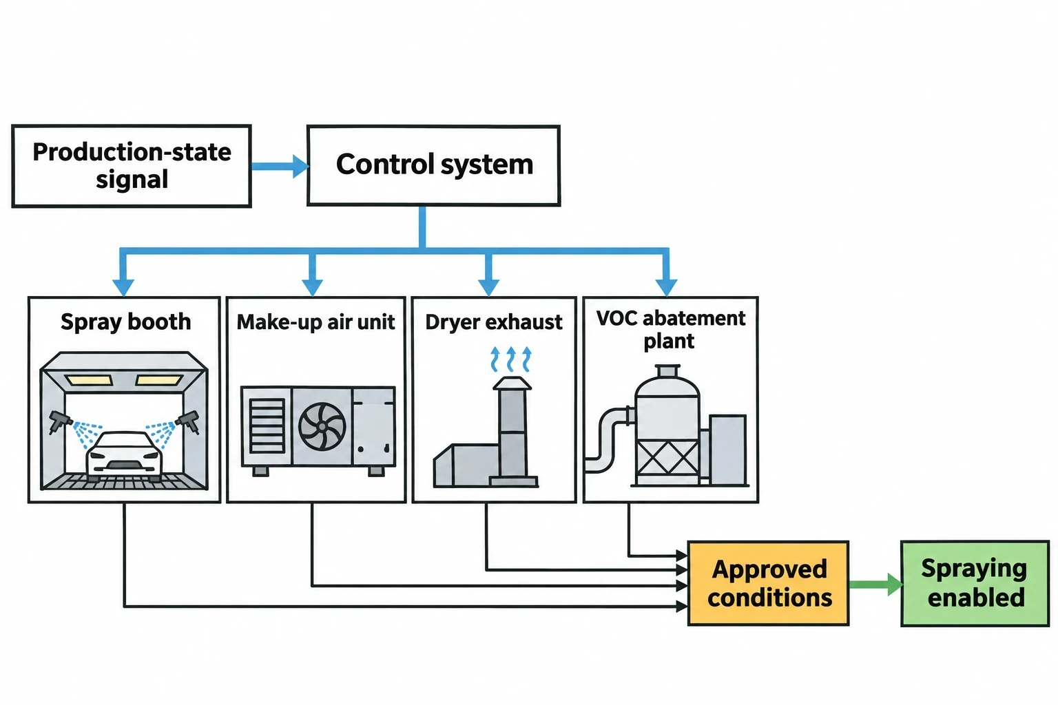
The highest-value change is often coordination. The booth, make-up air unit, dryer exhaust and abatement plant should respond to the same validated production-state signal, with equipment-specific safeguards.
A planned production stop should not leave booth fans at full duty while the make-up air unit conditions outside air for an empty process. Equally, operators or the building-management system should not permit spraying to resume until the booth has re-established its approved temperature, humidity, airflow, pressure and abatement conditions.
Production systems can supply body-present and line-state signals. The building-management or process-control system can execute the approved airflow sequence. EHS and paint-quality teams should approve the limits and verify performance after commissioning.

Identify where your plant is losing energy and quantify the savings potential — our audits map every heat source, sink, and waste stream in your facility.
What an automotive HVAC energy audit should measure
A credible HVAC energy audit starts with measured operating behaviour rather than design drawings or nameplate data. The BREF identifies incomplete metering as a barrier to comparing paint-shop energy performance, particularly where utility systems serve multiple process areas.
The measurement plan should separate fan electricity from heating, cooling and abatement demand. It should also capture the production state that explains each change in load.
Build a process-level metering plan
| Asset or system | Measurements | Control decision supported |
|---|---|---|
| Spray-booth supply and extract fans | kW, airflow, speed, pressure | Fan reset and airflow verification |
| Make-up air units | Thermal energy, chilled-water energy, supply temperature, relative humidity | Heating, cooling and humidity control |
| Spray booths | Differential pressure, supply and extract volume | Pressure cascade and idle-mode limits |
| VOC abatement | Energy input, inlet flow, operating status | Permissives for reduced-flow modes |
| Curing ovens and dryers | Fuel or electrical energy, exhaust flow, operating state | Coordinated production-state control |
| Paint line | Vehicle count, body gaps, downtime, shift state | Production-normalised energy indicators |
This boundary supports a defensible paint-shop kWh-per-vehicle indicator. It also allows teams to identify the asset causing a poor result rather than treating the department as one unexplained energy load.
Investigate trends that point to HVAC control faults
Trend data should cover normal production, low-volume shifts, breaks, planned maintenance, non-production periods and different weather conditions. The audit should compare the air-handling response with the actual line state.
Useful fault patterns include:
- Full fan speed during confirmed breaks or extended body gaps
- Supply and extract fans failing to track each other
- Booth pressure instability after airflow reset
- Heating and cooling coil demand occurring at the same time
- Supply-air temperature resetting without reference to booth demand
- Filter differential pressure rising beyond the maintenance threshold
- Persistent high extract volume while the relevant booth is idle
- Abatement status preventing a scheduled low-flow mode
- Unexplained differences in paint-shop kWh per vehicle between shifts
EnerTherm Engineering’s seven-step audit approach can structure this work from consultation and on-site assessment through instrumented measurement, data analysis, prioritised actions, implementation support and ongoing measurement and verification. In a paint shop, paint-quality and environmental representatives should participate from the initial survey because they define the operating envelope for each control change.
Verify savings and support ESOS reporting
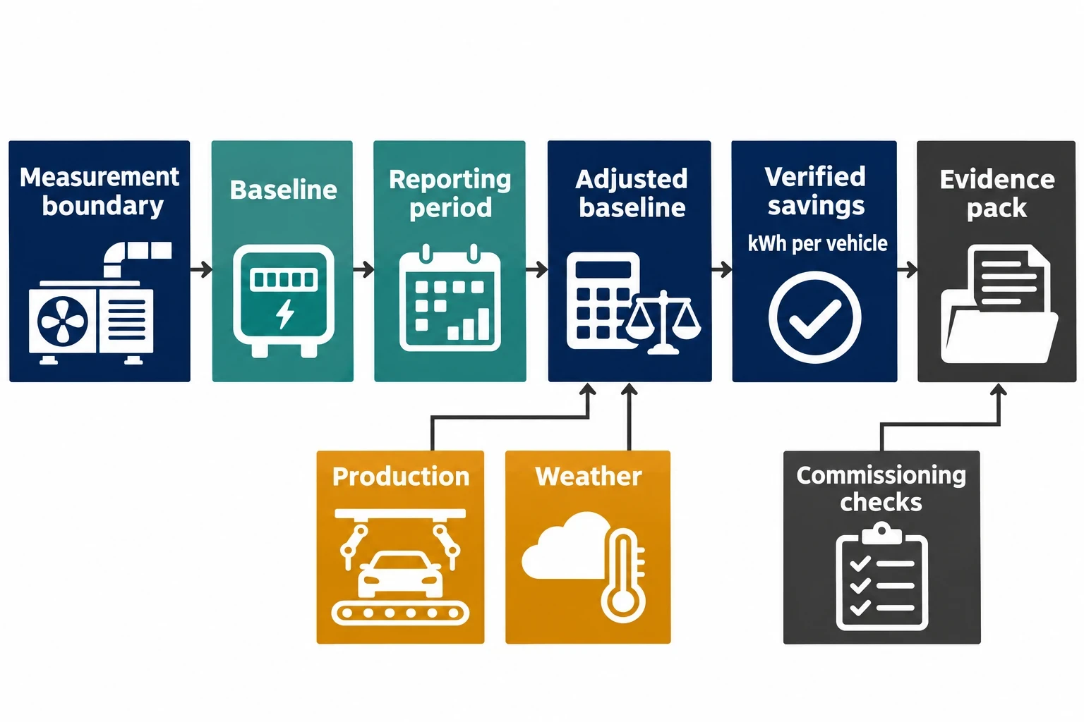
A lower utility bill does not, by itself, establish that a new HVAC sequence delivered the claimed saving. Vehicle volume, ambient temperature, humidity, model mix and operating hours can change during the same period.
IPMVP Core Concepts 2022 provides a recognised framework for defining the measurement boundary, baseline, reporting period, adjustment factors and data-quality checks. The aim is a transparent calculation that a facilities team, finance lead and external assessor can understand.
Match the measurement boundary to the intervention
A fan-speed reset project may use a narrow boundary around supply and extract fan electricity. A coordinated ventilation and thermal-control project should include electricity, heating energy, chilled-water energy and any abatement energy materially affected by the revised operating mode.
The baseline should record approved pre-project operating states, hours, airflow setpoints, energy use and independent variables. The reporting period should use the same data discipline. Where weather affects thermal demand, teams should account for it rather than attributing a mild season to the control change.
Commissioning evidence should include pressure trends, temperature and humidity results, alarm tests, abatement availability and paint-quality checks. The project record should explain exclusions, such as unrelated process loads or a concurrent production-line change.
ESOS Phase 3 creates a near-term reporting requirement
UK large undertakings within ESOS Phase 3 must submit the second annual progress update by 5 December 2026. The relevant reporting period is 6 December 2025 to 5 December 2026.
Participants must report implemented measures, identify whether action-plan measures were delivered, estimate energy savings for the reporting period and retain the calculation method in the evidence pack. Energy-intensity ratios are mandatory under the Phase 3 reforms, strengthening the case for a paint-shop indicator such as kWh per vehicle.
A demand-based HVAC project can provide a well-evidenced measure where the site holds:
- Baseline and post-installation energy data
- Vehicle count and operating-state data
- A description of the changed control sequence
- The approved airflow, quality and safety limits
- Adjustment assumptions for production and weather
- Evidence that abatement and permit conditions remained satisfied
- A repeatable method for estimating annual energy savings
ISO 50001:2018 supports longer-term management discipline. It provides a framework for energy baselines, energy performance indicators and operational control. For paint shops, this means embedding validated control states in standard operating practice and reviewing performance when production conditions change.
Making demand-based HVAC control stick
Control optimisation often begins with recommissioning, sensor checks, revised setpoints and improved operating sequences. Lasting value depends on keeping the logic visible and governed.
Each operating state should have an owner, an approved setpoint record, a change-control route and a periodic review. A low-flow mode introduced for one coating process may not suit a new paint chemistry, a revised abatement arrangement or a major change in vehicle throughput.
Monthly review should bring energy, production and quality information together. A rising kWh-per-vehicle figure may indicate an HVAC control issue, such as a booth locked at production airflow during idle periods or a humidity reset that has drifted. It may also reflect lower utilisation. The distinction matters because the remedy is different.
This article reflects the independent analysis and editorial opinion of EnerTherm Engineering. Product names, trademarks, and brands mentioned belong to their respective owners. EnerTherm Engineering is not affiliated with, endorsed by, or a licensee of any third-party software or product mentioned unless explicitly stated.

Managing Director — EnerTherm Engineering
Dr. François Pierrel is Managing Director of EnerTherm Engineering with over two decades of expertise in thermal design, heat transfer, and industrial energy optimisation. He holds a PhD in Heat Transfer from Cranfield University and a Post-Doctorate from Heriot-Watt University.
