Welding Transformer Efficiency Improvement Cuts Robot Power
Škoda Auto reports about 30% lower standby use, with hibernation cutting it by up to 85%
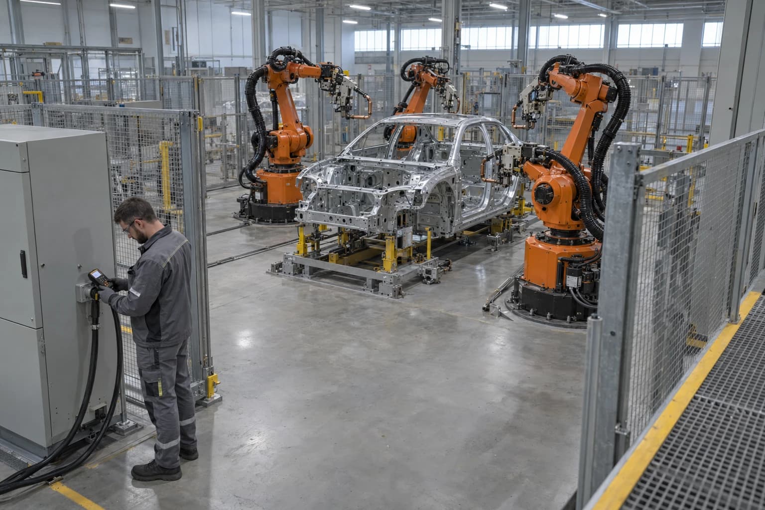
Welding transformer efficiency improvement reduces electrical losses in resistance-welding transformers and their power circuits while maintaining the current, force and timing needed to produce conforming welds. A typical Škoda Auto robotic welding line contains 600 to 700 robots, making energy used between welds as important to an audit as the short, high-current pulse used to form each spot weld.
For automotive body-in-white operations, electricity is distributed across robot controllers, welding controllers, gun transformers, cooling systems, conveyors and cell auxiliaries. Transformer losses and standby consumption occur in different operating states, so a line-level electricity meter cannot identify the underlying opportunity.
The target is lower kWh per vehicle without compromising weld nugget quality, availability or takt time. That requires a measured view of transformer condition, secondary-circuit resistance, cooling performance and robot-cell power states.
Why welding transformer efficiency matters
The transformer is a short but demanding load
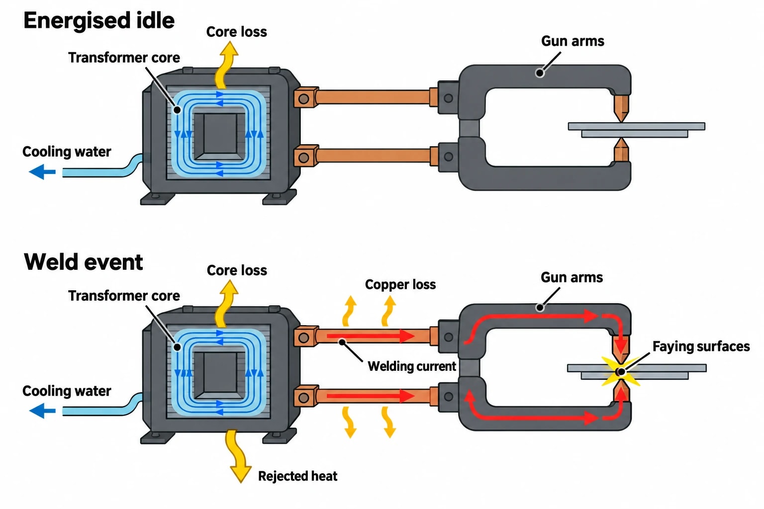
Resistance spot welding generates heat at the faying surfaces by passing controlled current through clamped sheet metal. The gun transformer reduces voltage and supplies the high current required for a brief weld event.
Not all electricity entering the welding cell reaches the weld interface. Losses occur in transformer windings, magnetic cores, rectifiers, cables, flexible shunts, busbars, gun arms and electrical joints. The resulting heat must be rejected through air or cooling water.
Transformer losses fall into two main categories:
- Core losses arise when an energised transformer magnetises its core. They can persist through non-weld periods where the primary remains energised.
- Copper losses arise from electrical resistance in windings and conductors. They increase with current and conductor temperature during welding.
An overheating transformer can affect insulation life, increase cooling demand and trigger protective trips. It may also indicate a deteriorating electrical path that creates unstable current delivery.
Energy per weld is only part of the picture
A high instantaneous weld demand does not necessarily create the largest annual electricity opportunity. Body shops often have long intervals of energised idle time, including material shortages, breaks, planned maintenance, shift handovers, model changes and weekend shutdowns.
An effective welding transformer efficiency improvement programme separates:
- Energy used during active welding.
- Transformer and controller consumption during energised idle periods.
- Robot-controller consumption during short and long production gaps.
- Cooling-system electricity associated with rejected heat.
- Consumption during planned and unplanned downtime.
This avoids a common audit error: specifying new transformer hardware where robot standby or poor shutdown discipline accounts for more annual consumption.

Identify where your plant is losing energy and quantify the savings potential — our audits map every heat source, sink, and waste stream in your facility.
How to audit welding transformer efficiency improvement
Establish a production-normalised baseline
The baseline should combine electrical measurements with production records. Useful indicators include kWh per vehicle, kWh per bodyshell, kWh per panel and kWh per 1,000 welds.
Each metric has a different purpose. kWh per vehicle gives management a plant-relevant figure. kWh per 1,000 welds helps engineers compare similar cells where production volume or model mix changes. Neither metric should be interpreted without the other operating variables.
A representative monitoring period should include full production, short breaks, meal breaks, planned maintenance and a non-production period. The audit record should identify:
- Vehicle programme and bodyshell count.
- Weld count and weld-family mix.
- Shift pattern and scheduled breaks.
- Robot and welding-controller states.
- Significant stoppages and maintenance activity.
- Cooling-water alarms, flow issues and temperature changes.
- Changes to electrodes, shunts, guns or welding schedules.
A meter at the line incomer gives an overall baseline. Sub-metering at welding-controller groups, robot-cell distribution boards and selected welding transformers locates the load more accurately.
Capture the correct electrical data
Power analysers should capture voltage, current, real power, energy, power factor and maximum demand. The sampling method needs sufficient resolution to distinguish rapidly changing welding demand from the lower, persistent load of controllers and idle equipment.
A measurement boundary must be defined before monitoring begins. For a transformer comparison, it may include the welding controller and transformer input. For a cell standby project, it should include robots, welding controllers, transformers and relevant cooling auxiliaries.
Thermal imaging adds useful evidence alongside electrical readings. It can identify unusually hot terminals, transformer enclosures, busbars and cooling connections. A high temperature alone does not prove an efficiency defect. Engineers should compare equipment with similar duty, weld count and ambient conditions.
Compare comparable guns and duties
A transformer welding thick structural material should not be compared directly with one welding a light-gauge bracket. Group equipment by material stack, gun configuration, weld count, weld schedule and production duty.
A rising energy-per-weld figure may indicate increased electrical resistance, altered weld time, schedule changes, higher conductor temperature or a measurement boundary that includes another load. Review the weld-quality record before changing a schedule.
Weld quality remains the controlling condition. Process engineers should validate changed schedules through the plant’s approved destructive testing, non-destructive testing and quality procedures. Reduced electricity use has little value if it creates rework, scrap or quality containment.
Where resistance-welding transformer losses arise
Secondary-circuit resistance raises unwanted heat
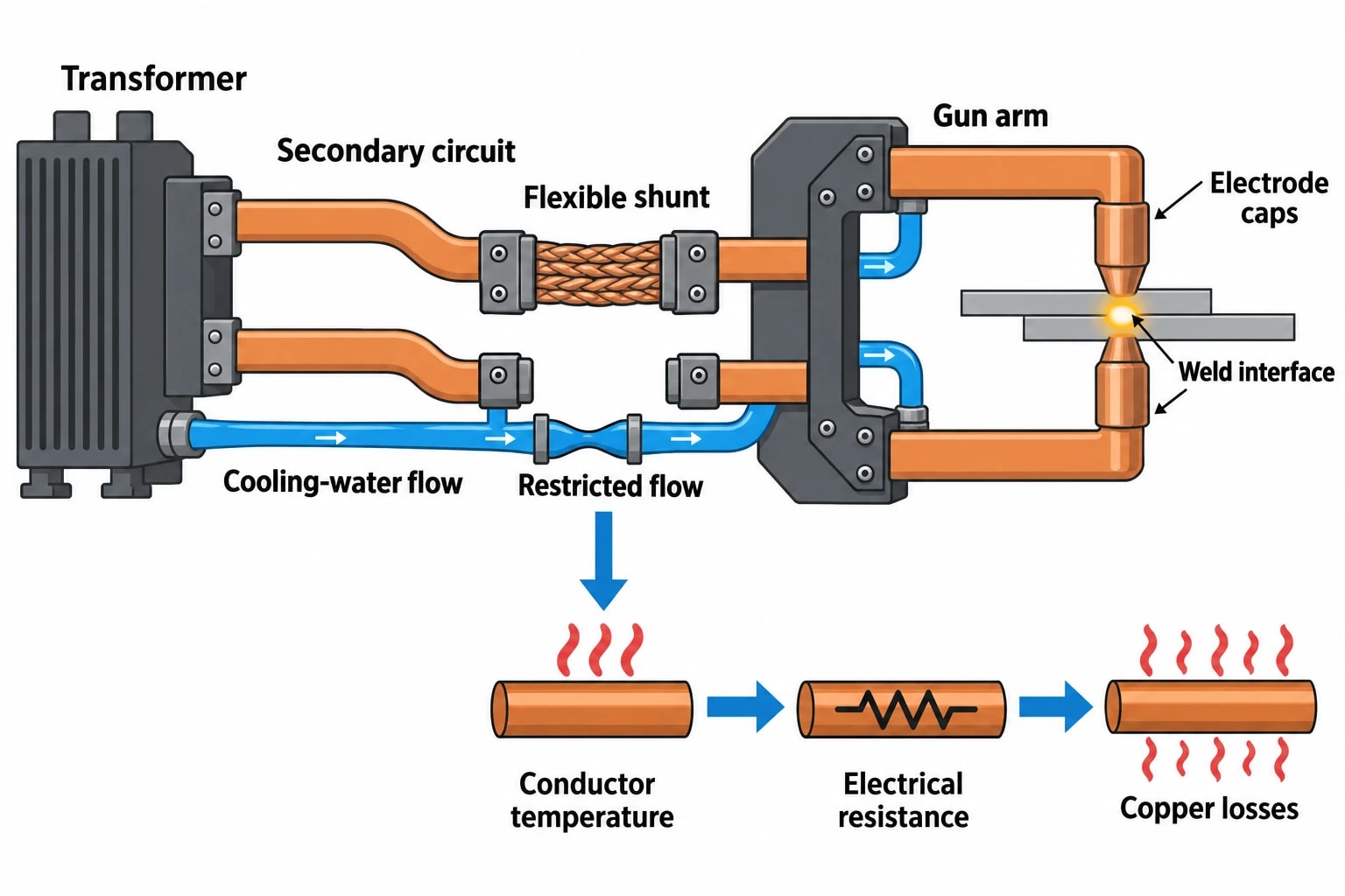
The secondary circuit carries very high current. Its condition therefore matters to both energy use and weld consistency. The circuit can include transformer connections, rectifier connections, flexible shunts, busbars, gun arms, electrode holders and electrode caps.
Higher resistance produces heat outside the intended weld interface. The controller may then require more input energy to achieve the required current profile.
Maintenance inspections should focus on:
- Loose, oxidised or contaminated bolted connections.
- Damaged flexible shunts and conductors.
- Worn electrode caps or poor electrode dressing.
- Incorrectly fitted secondary components.
- Corrosion at contact surfaces.
- Water leaks or cooling restrictions near current-carrying parts.
These checks belong in routine welding maintenance rather than being treated solely as an energy project. Restoring a sound secondary path can improve current delivery and reduce avoidable heat.
Cooling performance affects electrical loss
Restricted cooling-water flow can increase transformer and conductor temperature. As conductor temperature rises, electrical resistance also rises, increasing copper losses during welding. A cooling fault can therefore appear in both thermal and electrical data.
The objective is not the highest possible flow rate. Excess flow carries pumping, water-treatment and maintenance costs. The correct condition is stable operation within the equipment manufacturer’s specified flow and temperature limits.
Audit teams should record inlet and outlet temperatures, water flow where available, alarm history and visible condition of cooling connections. Comparisons should be made after similar production runs, rather than between a heavily used gun and one that has been idle.
MFDC upgrades need a measured business case
What ISO 22829:2017 covers
Medium-frequency direct-current welding guns use an inverter-driven transformer-rectifier arrangement. ISO 22829:2017 specifies additional requirements to ISO 5826:2014 for integrated transformer-rectifier units used on DC welding guns operating at 1,000 Hz, with rated input voltage not exceeding 1,000 V.
ISO 5826:2014 provides general specifications for resistance-welding transformers. It covers single-phase AC transformers, transformer-rectifier units and inverter transformers with connected rectifiers. ISO 22829:2017 supplements those requirements for its defined transformer-rectifier application.
These standards provide technical context for equipment specification and testing. They do not demonstrate that an individual MFDC upgrade will reduce annual electricity consumption. The site still needs a measured baseline, a clear operating profile and weld-quality validation.
Assess the complete electrical path
An MFDC project should assess the complete system rather than comparing transformer nameplate ratings alone. The review should include the welding controller, transformer-rectifier, secondary circuit, cooling demand, robot integration, installation downtime and spare-parts provision.
Capital planning should address six questions:
-
Does the existing transformer show abnormal heat, high loss, failure history or unstable electrical performance?
-
What proportion of annual cell electricity occurs during active welding, energised idle and robot standby?
-
Can maintenance of shunts, electrodes, joints and cooling equipment remove part of the loss first?
-
Will the proposed equipment preserve robot payload, access, cable routing and cycle time?
-
What weld validation is required across each material stack and weld family?
-
How will energy and quality be measured before and after commissioning?
The financial model should distinguish between energy savings, maintenance avoidance and a reliability replacement that would have occurred regardless of the project. Combining those categories can overstate the energy case.

Identify where your plant is losing energy and quantify the savings potential — our audits map every heat source, sink, and waste stream in your facility.
Robot standby power can exceed transformer gains
Planned breaks are an energy condition
The Škoda Auto robotic-welding-line study reported that robot standby modes can reduce robot consumption by about 30%, while hibernation can reduce it by up to 85%. The team reported about 5% savings in total robot-cell consumption through appropriate use of these modes during weekends and scheduled breaks.
Those findings are a useful reference point, not a guaranteed outcome for a UK body shop. Controller configurations, safety functions, restart times, production plans and equipment ages differ between sites.
An audit should map predictable intervals and assign an approved energy state to each one.
| Operating period | Audit question | Potential action |
|---|---|---|
| Micro-stop | Can the cell enter an approved low-power state without delaying recovery? | Apply standby logic |
| Meal break | Which controllers and auxiliaries remain fully energised? | Co-ordinate standby settings |
| Planned maintenance | Can welding equipment be safely isolated after handover? | Use documented isolation routines |
| Weekend shutdown | Which systems can hibernate or switch off? | Use shutdown and restart checklists |
| Start-up | Can equipment energise in stages? | Sequence controllers and auxiliaries |
Audit the cell as a connected load group
A robot in standby may reduce controller consumption while the welding controller, transformer cooling circuit or ancillary supply continues to run. The cell should therefore be audited as a connected load group.
For each operating state, manufacturing engineering, maintenance, production and safety teams should identify what must remain live for safety, quality traceability and orderly restart. They should then identify equipment that can reduce load or be switched off.
The result should be a documented state matrix linked to the production schedule. Informal practices often disappear when shift patterns change or production recovery takes priority.
Regulation and standards: use the right reference
Arc-welding ecodesign limits do not apply to resistance welding
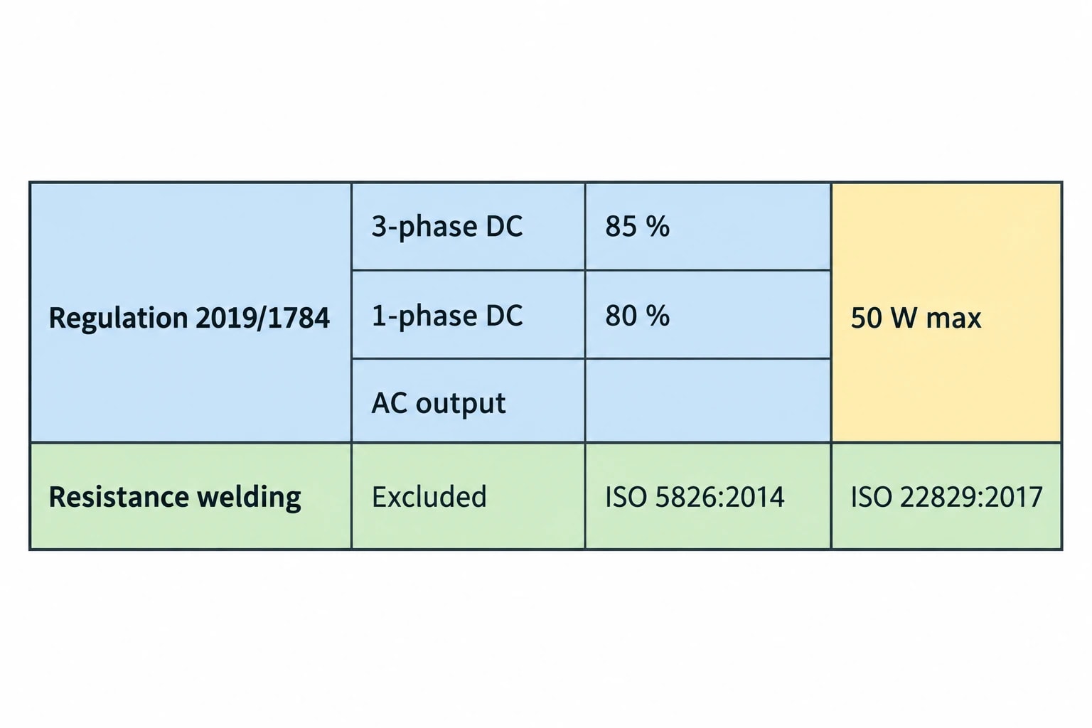
UK-retained Commission Regulation (EU) 2019/1784 sets minimum power-source efficiency requirements and a 50 W maximum idle-state limit from 1 January 2023 for welding equipment within scope. The regulation specifies 85% minimum efficiency for three-phase DC-output equipment and 80% for single-phase DC-output and AC-output equipment.
Automotive spot-welding transformers must not be assessed against those limits as mandatory requirements. The regulation explicitly excludes resistance welding. Its scope covers specified arc-welding and allied processes, rather than the resistance-welding equipment used in body-in-white production.
For resistance-welding transformer work, ISO 5826:2014 and ISO 22829:2017 provide the relevant technical standards context. Plant-specific process approval and weld-quality requirements determine whether a changed installation is acceptable for production.
Build evidence into energy management
ISO 50001:2018 provides a framework for systematic energy-performance improvement. A welding-line project can support this approach by identifying the significant energy use, setting a baseline, defining relevant variables and reviewing verified results.
The evidence package should state:
- The electrical measurement boundary.
- Baseline and reporting periods.
- Production volume, model mix and weld count.
- Changes to schedules, equipment or operating hours.
- Quality results before and after implementation.
- Meter accuracy, sampling method and data gaps.
This makes savings claims traceable and prevents a quiet production week from being reported as a transformer efficiency improvement.
Turning audit findings into lower kWh per vehicle
Welding transformer efficiency improvement should begin with condition and operating-state evidence, then move through practical actions in a controlled order.
-
Repair electrical and cooling faults that increase losses.
-
Improve maintenance of electrodes, shunts, joints and secondary-circuit components.
-
Apply approved robot and cell standby schedules for predictable breaks.
-
Review welding schedules only through controlled weld-quality validation.
-
Assess MFDC transformer-rectifier upgrades where measured duty and equipment condition support the case.
-
Verify kWh per vehicle and kWh per weld after implementation.
EnerTherm Engineering’s automotive energy-audit work can support this process through initial assessment, on-site measurement using power analysers and thermal imaging, production-normalised analysis, implementation planning and measurement and verification.
The strongest projects measure the loss path, maintain the secondary circuit, control energised idle time and align robot power states with the production schedule. This reduces non-production electricity use while protecting weld quality and throughput.
This article reflects the independent analysis and editorial opinion of EnerTherm Engineering. Product names, trademarks, and brands mentioned belong to their respective owners. EnerTherm Engineering is not affiliated with, endorsed by, or a licensee of any third-party software or product mentioned unless explicitly stated.

Managing Director — EnerTherm Engineering
Dr. François Pierrel is Managing Director of EnerTherm Engineering with over two decades of expertise in thermal design, heat transfer, and industrial energy optimisation. He holds a PhD in Heat Transfer from Cranfield University and a Post-Doctorate from Heriot-Watt University.
