HMB Validates Chemical Manufacturing Capacity Expansion
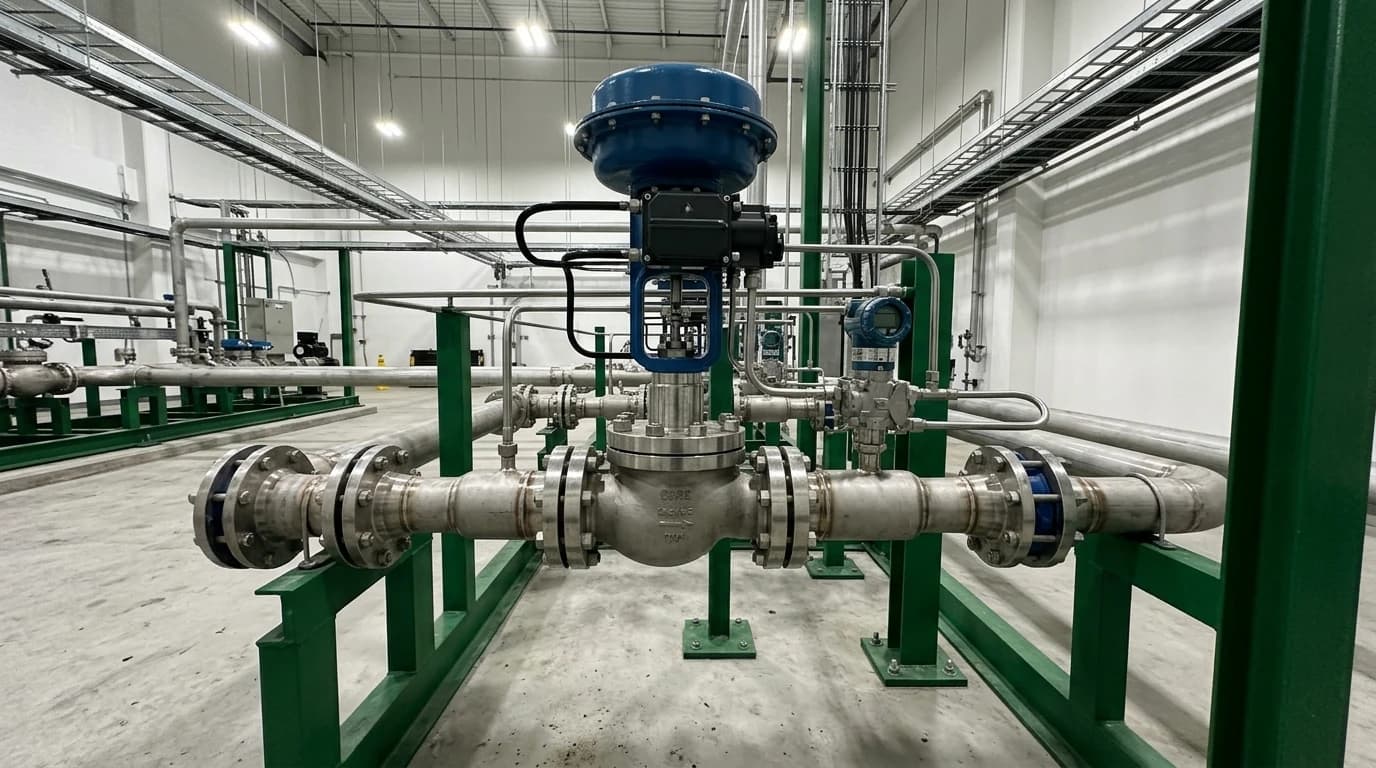
Sizing valves to BS EN 60534-2-1:2011 to prevent localised choking during scale-up.
Managing Chemical Manufacturing Capacity Expansion in a Contracting UK Sector
In March 2026, the Chemical Industries Association (CIA) issued an urgent statement highlighting that UK chemical sector output had fallen by approximately 40 to 60 per cent since 2021. This decline stems from structural challenges, particularly energy costs that average three to four times higher than those of global competitors. For instance, North American petrochemical manufacturers operate with cheap, ethane-rich feedstocks, whereas European and UK facilities rely on more expensive naphtha cracked components. Over the past five years, these pressures contributed to the closure of at least 25 major chemical manufacturing sites across the UK. In this difficult fiscal environment, capital project directors cannot justify the high capital expenditure required for greenfield construction.
Capital Prioritisation Amid Shrinking Production and High Energy Tariffs
High utility tariffs directly erode the operating margins of speciality and petrochemical operations. When natural gas and electricity prices spike, plant operators must find immediate efficiency gains to remain solvent. Chemical manufacturers are redirecting their limited capital allocations away from speculative greenfield expansions. Instead of building new facilities, they focus on extracting maximum capacity from existing plant footprints. This shift in capital prioritisation requires process engineers to re-evaluate the physical boundaries of installed equipment, pushing systems beyond their original design limits.
Bypassing High CapEx via Brownfield Debottlenecking
Brownfield debottlenecking allows chemical manufacturers to execute a cost-effective chemical manufacturing capacity expansion with minimal capital investment. By targeting specific constraints, plant operators can achieve a 10 to 30 per cent increase in throughput at a fraction of the cost of building a new processing line. However, expanding the capacity of an operating plant introduces significant thermodynamic and hydraulic risks. Scaling up feed rates without performing a complete heat and mass balance validation can lead to off-spec product, excessive energy consumption, and dangerous localised overpressure. Consequently, capital project directors require a reliable methodology to validate equipment sizing and process safety before executing a brownfield capacity expansion.

Map every energy and material flow in your process with detailed heat and mass balance calculations — the foundation for any optimisation or design project.
Decarbonisation Readiness and Regulatory Constraints
Capacity scale-up projects do not occur in a regulatory vacuum. On 28 February 2026, the Environment Agency implemented major amendments to standard rules permits under the Environmental Permitting (England and Wales) Regulations 2016. These new rules require that operators of new or substantially refurbished electricity-generating combustion plants, including combined heat and power (CHP) units and steam-raising boilers commonly used in chemical manufacturing, must submit a Decarbonisation Readiness (DR) report as part of their environmental permit application.
The Environment Agency Permitting Amendments of 2026
The Environment Agency enforces these guidelines to prevent industrial assets from becoming stranded during the transition to a low-carbon economy. Any capacity expansion that requires a substantial refurbishment of existing boilers or CHP systems must comply with these new rules. Under the amended regulations, operators must provide detailed technical assessments proving that their modified utility systems can transition to low-carbon operations, such as hydrogen combustion or carbon capture, in the future. This regulatory change adds a layer of design constraints to any capacity scale-up project.
Space and Technical Requirements for Low Carbon Retrofits
Complying with the Decarbonisation Readiness requirements means proving that the facility has reserved sufficient physical space for future carbon capture absorbers, solvent regeneration units, or hydrogen blending skids. Additionally, the process design must accommodate the future dynamic behaviours of these low-carbon systems, such as altered thermal profiles and increased utility demands. If an engineering team scales up plant throughput without considering these space and utility integration limits, the regulator may deny the required environmental permit, stalling the entire expansion project.
Thermodynamic Validation of Chemical Manufacturing Capacity Expansion
Evaluating a chemical manufacturing capacity expansion requires a high-fidelity Heat and Mass Balance (HMB) model. The thermodynamic foundation of this model relies on selecting the correct property packages to represent the physical behaviour of complex fluid mixtures.
Thermodynamic Modelling of Phase Equilibrium and Reactor Kinetics
In speciality chemical and petrochemical plants, process design teams typically select thermodynamic models such as Non-Random Two-Liquid (NRTL) or UNIQUAC for highly non-ideal polar mixtures, or Soave-Redlich-Kwong (SRK) and Peng-Robinson equations of state for high-pressure hydrocarbon systems. By implementing these models in process simulation software such as Aspen Plus, HYSYS, or DWSIM, process engineers can calculate the exact phase behaviour, vapour-liquid equilibrium (VLE), and liquid-liquid equilibrium (LLE) of the process streams. This thermodynamic validation is essential when scaling up exothermic batch reactors or continuous reactive distillation columns, where heat generation rates and phase separation boundaries shift non-linearly with feed rate increases.
Establishing the Single Source of Truth Process Flow Diagram (PFD)
The final output of an HMB validation is a validated Process Flow Diagram (PFD) that serves as the single source of truth for the entire engineering, procurement, and construction (EPC) lifecycle. This diagram contains embedded stream tables displaying the temperature, pressure, enthalpy, mass flow, and species-level composition of every stream in the expanded plant. Additionally, engineers compile Sankey energy maps to track thermal energy inputs, useful heat duties, and stack losses across the process. This rigorous accounting ensures that species-level mass balances and thermodynamic energy balances close perfectly, leaving no unaccounted energy losses or mass accumulation in recycle loops.
Dynamic Constraints and Hydraulic Bottlenecks in Speciality Plants
Industrial chemical plants are dynamic systems. A capacity expansion that appears feasible in a steady-state simulation can fail during actual operations because the binding process constraint changes based on seasonal utilities, feedstock ratios, or catalyst performance.
Predicting Column Hydraulics and Heat Exchanger Fouling Tolerances
In distillation columns, increasing the vapour and liquid traffic to achieve higher throughput can push the tower toward its hydraulic limits. Process engineers must model column internal behaviour using HMB validation to predict localised flooding, weeping, entrainment, and downcomer backup. Similarly, thermal design teams must evaluate heat exchangers under worst-case summer cooling water temperatures and maximum fouling factor tolerances. If a heat exchanger lacks the thermal margin to handle the increased load during peak summer conditions, the system will face localised temperature runaways or off-spec product separation.
Simulating Transient Upset Scenarios and Relief System Adequacy
To prevent catastrophic failures, thermal design teams must transition their steady-state HMB models into dynamic simulations to capture transient plant behaviour. These dynamic models allow engineers to conduct virtual safety assessments of common upset scenarios. These scenarios include sudden loss of cooling water, instrument failures, power outages, and rapid changes in feedstock composition. By simulating these transient events, engineers can determine whether existing pressure relief valves (PRVs) and safety-critical trip systems have the capacity to handle the increased volumetric flow and pressure buildup. Dynamic modelling prevents unnecessary relief valve activations, protecting the environment and avoiding costly plant shutdowns.

Map every energy and material flow in your process with detailed heat and mass balance calculations — the foundation for any optimisation or design project.
Valve Sizing and Fluid Flow Safety Under Installed Conditions
During a chemical manufacturing capacity expansion, the optimisation of industrial-process control valves under installed conditions represents a major safety and process limit. As throughput increases, control valves must regulate higher flow rates while maintaining precise pressure drop profiles.
Compliance with BS EN 60534-2-1:2011 Sizing Equations
To ensure mechanical and hydraulic integrity, the sizing equations and dynamic behaviour of these safety-critical valves must conform to BS EN 60534-2-1:2011 standards. These equations predict how compressible and incompressible fluids behave under installed piping configurations, accounting for the pressure recovery characteristics of different valve geometries.
For an incompressible fluid, the basic flow sizing equation used to calculate the required valve flow coefficient (Kv) under non-cavitating conditions is:
Kv=QΔPρ
Where:
Kv is the valve flow coefficient (m³/h).
Q is the volumetric flow rate of the fluid (m³/h).
ρ is the density of the fluid relative to water (dimensionless).
ΔP is the net pressure drop across the control valve under installed conditions (bar).
Preventing Localised Choking and Overpressure
As flow rates rise, the pressure drop across a control valve increases. If the localised pressure drops below the vapour pressure of the liquid, flashing or cavitation occurs. Under these conditions, the fluid flow becomes choked, meaning that a further increase in pressure drop will not increase the flow rate. Process engineers must evaluate the pressure recovery factor (FL) and terminal pressure drop ratio (xT) within their sizing calculations as defined in BS EN 60534-2-1:2011 to identify where choked flow or localised flashing might occur. Ignoring these equations during a capacity expansion can cause severe valve erosion, high-frequency vibration, and localised overpressure upstream of the valve, ultimately destabilising the process chemistry and risking physical damage to pipeline networks.
Implementing a Standardised 11-Step Engineering Methodology
To execute a successful capacity scale-up, engineering teams follow a systematic 11-step framework to transition from raw plant data to a validated, optimised facility design.
Data Gathering, Calibration, and Steady-State Modelling
The process begins with project scoping and detailed data gathering. Engineers collect Piping and Instrumentation Diagrams (P&IDs), historical Distributed Control System (DCS) logs, laboratory assay results, and equipment data sheets. Once the physical data is compiled, process engineers construct a steady-state simulation model. This model undergoes rigorous calibration, during which thermodynamic parameters and kinetic reactions are adjusted until the simulation output matches actual operating data within a tight tolerance, typically ±1 per cent on mass balance and ±2 per cent on energy profiles.
Dynamic Validation, Safety Verification, and Carbon Optimisation
Once the design team calibrates the steady-state model, process engineers develop dynamic scenarios to analyse the transient limits of the system. In this step, engineers calculate tray-by-tray column hydraulics, execute heat exchanger pinch analysis, and verify control valve capacities against the BS EN 60534-2-1:2011 sizing equations under expanded flow conditions. Next, the engineering team adjusts the model to incorporate the Decarbonisation Readiness requirements mandated by the Environment Agency. This step ensures that any modifications to energy-intensive assets do not conflict with the UK Net Zero pathway. The final steps of the methodology produce actionable design deliverables: validated simulation models, equipment sizing summaries, modified PFDs, and a detailed economic analysis showing capital project directors the exact CapEx, operational expenditure (OpEx), carbon reduction potential, and investment payback period.
Case Study: Resolving Hydraulic and Thermal Constraints in a Petrochemical Plant
To illustrate this methodology, consider a UK speciality petrochemical facility scaling up its primary distillation train by 25 per cent.
Dynamic Feed Ratio Shifts and Distillation Columns
In this system, the feed ratio of light to heavy organics fluctuates dynamically based on upstream reaction yields. In a steady-state simulation, the column hydraulics appeared acceptable. However, during the validation phase, dynamic HMB modelling revealed that a 5 per cent increase in the light key fraction in the feed caused immediate downcomer flooding on trays 14 through 18. This flooding reduced the separation efficiency, causing the product to fall out of specification within minutes. By running dynamic hazard and transient simulations, process engineers identified the optimal adjustments to the column reflux ratio and recommended preheat temperature settings, allowing plant operators to implement these changes safely and avoid a costly, high-CapEx tray replacement project.
Reactor Cooling Limit Analysis and Exothermic Heat Duties
The same petrochemical expansion required a 20 per cent increase in feed rate to the primary exothermic reactor. At the original throughput, the reactor cooling jacket successfully maintained a constant reaction temperature of 85 °C. Kinetic analysis of the reaction chemistry, however, indicated that heat generation would scale non-linearly due to localised concentration spikes. By modelling the system under varying summer cooling water temperatures, peaking at 28 °C utility supply temperature, the design team discovered that the heat exchanger network lacked the thermal pinch margins required to reject this additional load. Process engineers using HMB validation identified that by installing a small, targeted auxiliary heat exchanger and having operators adjust the cooling water loop flow control valve, the facility could maintain the reactor temperature under all seasonal conditions, preserving product yield and preventing runaway reactions.
Quantifying Project Payback and Carbon Reduction Metrics
By systematically applying HMB validation to capacity scale-up projects, chemical manufacturers secure substantial operational savings.
Energy Cost Mitigation and Operating Margin Efficiencies
In the high-cost UK energy market, identifying where thermal energy can be recycled back into the process is essential. For instance, pinch analysis conducted during the mass and energy balance validation can identify opportunities to preheat reactor feed streams using hot distillation column bottoms. Implementing these heat integration opportunities reduces the load on utility steam boilers, directly lowering gas consumption. For a medium-sized speciality chemical plant, a 15 per cent reduction in steam utility demand can translate into several hundred thousand pounds of annual operational savings, yielding a rapid payback on the engineering validation project.
CO₂ Emissions Reduction and Compliance with Net Zero Pathways
Lowering fuel consumption in boilers and heaters directly reduces Scope 1 carbon emissions. As the UK Emissions Trading Scheme (ETS) tightens its free allocation rules and Decarbonisation Readiness standards become mandatory for refurbished combustion units, carbon mitigation becomes a critical compliance requirement. HMB validation provides chemical manufacturers with the verified emission reduction data needed to support environmental permit amendments. Rather than relying on generic estimates, plant operators can present the Environment Agency with precise, thermodynamic-backed calculations of carbon reduction. This empirical approach ensures that capacity expansion projects remain fully aligned with the UK Net Zero pathway, avoiding future carbon penalties and securing the long-term viability of the manufacturing facility.
This article reflects the independent analysis and editorial opinion of EnerTherm Engineering. Product names, trademarks, and brands mentioned belong to their respective owners. EnerTherm Engineering is not affiliated with, endorsed by, or a licensee of any third-party software or product mentioned unless explicitly stated.

Managing Director — EnerTherm Engineering
Dr. François Pierrel is Managing Director of EnerTherm Engineering with over two decades of expertise in thermal design, heat transfer, and industrial energy optimisation. He holds a PhD in Heat Transfer from Cranfield University and a Post-Doctorate from Heriot-Watt University.
