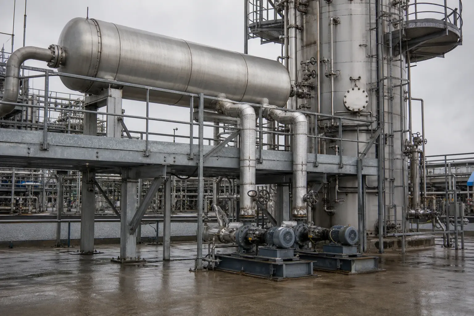
How Distillation Column Optimisation Cuts Utility Demand
Simulation-led reflux optimisation and heat integration target 20-60% energy savings.
Distillation column optimisation adjusts operating conditions, hydraulics and heat recovery to achieve the required separation with the least practicable reboiler and condenser duty.
A distillation train can meet product specification yet consume far more steam and cooling water than necessary. Excess reflux, unstable pressure control, fouled exchangers, an unsuitable feed condition or a conservative purity target all increase utility demand. The reboiler generates vapour throughout the column, while the overhead system rejects much of that latent heat.
For UK petrochemical, speciality chemical and fine chemical plants, the task is to separate energy that creates separation from energy that compensates for poor operation, poor data or hidden constraints. A validated heat and mass balance provides that distinction. It also prevents a site cutting steam only to lose product purity, hydraulic margin or controllability.
The Department for Energy Security and Net Zero’s March 2026 report, Updating evidence on energy efficiency potential for UK industry, defines energy efficiency as reducing delivered energy consumed per unit of industrial output. For distillation, that means measuring energy per tonne of on-specification product alongside recovery and throughput, rather than celebrating lower hourly steam flow during reduced production.
Why distillation column optimisation has such a large utility effect
Reboiler duty and reflux are tightly linked
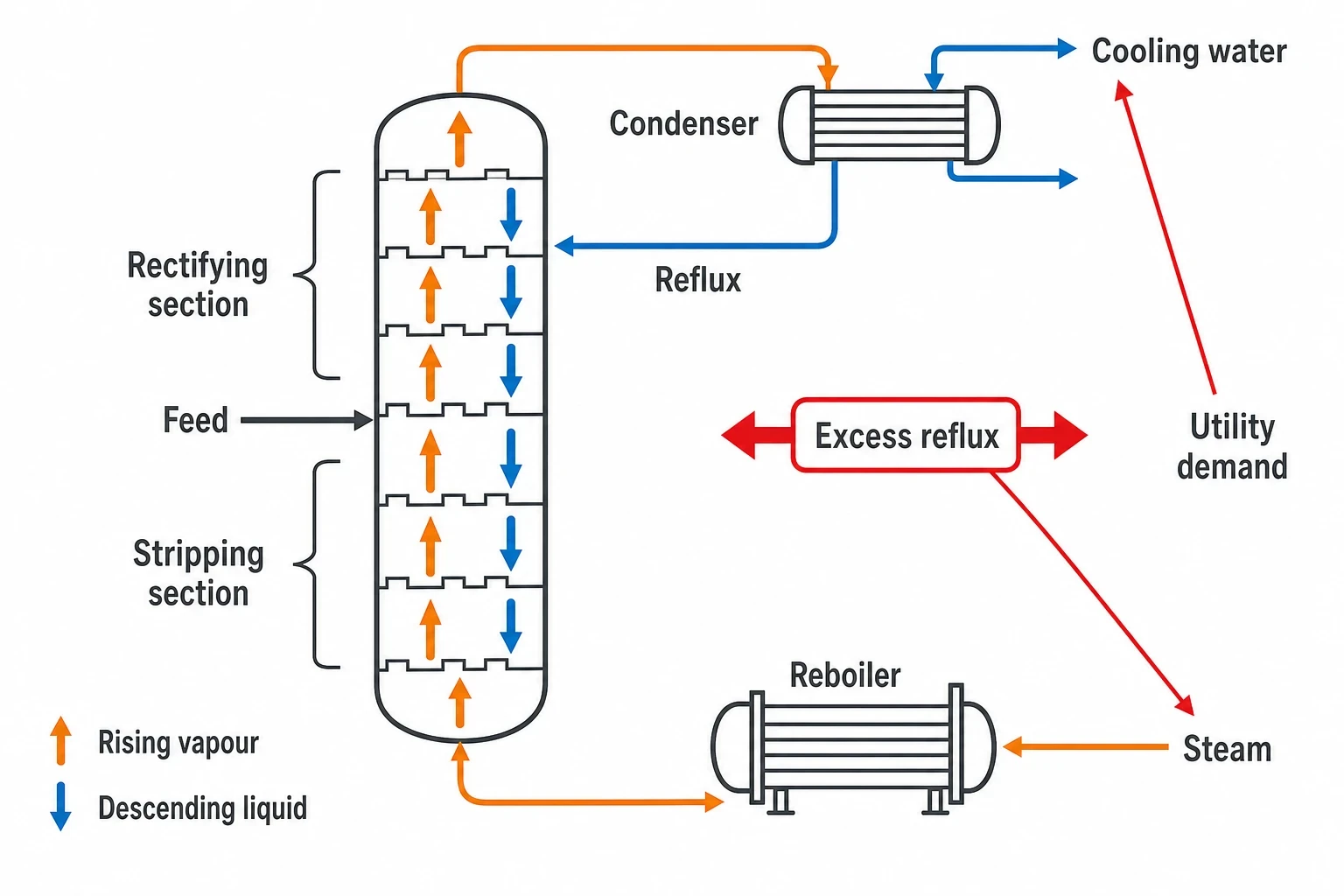
The reboiler supplies vapour that rises through the column. This vapour contacts descending liquid, enriching volatile components towards the top and less volatile components towards the bottom. Reflux returns cooled overhead liquid to the upper trays or packing and strengthens rectification.
Higher reflux can improve separation, but it also raises internal liquid and vapour traffic. The reboiler requires more steam and the condenser rejects more heat. A plant holding a reflux ratio above that required for product specification pays twice: in steam and in cooling demand.
The target is the minimum stable reflux that delivers the agreed distillate purity, bottoms quality and recovery across normal feed variability. It is rarely a fixed valve position or reflux-flow setpoint. It changes with feed composition, feed temperature, pressure, throughput and product specification.
Pressure changes alter the whole utility problem
Column pressure determines relative volatility, vapour density and boiling temperature. It also sets the temperature at which the condenser rejects heat and the reboiler receives heat.
Lowering pressure can improve relative volatility for many systems and reduce the number of theoretical stages required. It may permit a lower reboiler temperature, allowing lower-pressure steam or recovered process heat to supply the duty. The condenser must then operate at a lower temperature, however. Cooling-water approach temperatures, condenser area and vacuum-system capacity can become limiting.
Increasing pressure can permit overhead condensation against cooling water where refrigeration or vacuum operation would otherwise be required. It raises bottoms temperature and may require higher-pressure steam. Thermal degradation, corrosion, polymerisation and relief-system implications can also limit the pressure range.
Pressure optimisation is a column-and-utilities calculation, not an instruction to run at the lowest possible pressure.
Feed condition matters as much as feed rate
A cold or partially vaporised feed changes vapour and liquid traffic around the feed tray. The reboiler may need to supply heat that a feed preheater, upstream exchanger or flash arrangement could provide more efficiently. An overly hot feed can overload the rectifying section or condenser.
A rigorous model tests actual feed enthalpy rather than relying on nominal temperature. This matters after changes in upstream reactor conversion, solvent recovery, seasonal cooling-water temperature or recycle composition. Feed quality can also vary between campaigns in fine chemical manufacture, where one set of column targets may not suit every batch.

Map every energy and material flow in your process with detailed heat and mass balance calculations — the foundation for any optimisation or design project.
Start with a validated heat and mass balance
Build a reliable operating baseline
Distillation column optimisation begins by reconciling plant evidence. P&IDs, historical trends, laboratory assays, tank movements, steam-flow records, cooling-water measurements and maintenance history must describe the same operating case.
A useful baseline includes:
- Feed flow, composition, temperature and pressure.
- Distillate, bottoms and side-draw flow, composition and product specifications.
- Reflux flow, reboiler steam flow and condensate condition.
- Column pressure profile and pressure drop.
- Top, feed-zone and bottom temperatures.
- Condenser cooling-water inlet and outlet temperatures, or refrigeration duty.
- Reboiler and condenser approach temperatures.
- Differential pressures across trays, packing, filters and exchangers.
- Vent, flare, purge and recycle flows.
A mass balance that closes only after unexplained adjustments is not a sound basis for reducing utilities. Flow-meter bias, unmeasured water ingress, uncertain laboratory analysis and changing inventories in reflux drums or receivers can create false optimisation opportunities.
Select the right thermodynamic model
The thermodynamic package determines simulated vapour-liquid equilibrium, enthalpy and phase behaviour. An unsuitable package can predict an attractive steam saving that fails when plant conditions change.
Process engineers commonly assess NRTL or UNIQUAC for strongly non-ideal liquid mixtures, and SRK or Peng-Robinson equations of state for hydrocarbon-rich and higher-pressure systems. Liquid-liquid equilibrium or vapour-liquid-liquid equilibrium may be essential where water, entrainers, salts or partially miscible solvents influence separation. Azeotropic systems need particular care because a pressure or reflux change can shift phase behaviour rather than deliver a straightforward purity improvement.
Plant data should test the model at more than one condition where possible. A model that reproduces one steady-state test can still be unreliable away from that point. Validation should compare measured product quality, temperature profile, pressure drop, reboiler duty and condenser duty, then test upset cases such as a feed-composition shift or cooling-water temperature rise.
Turn the model into a single source of truth
EnerTherm Engineering’s 11-step Heat and Mass Balance framework includes project scoping, data gathering, steady-state and dynamic simulation, validation and actionable recommendations. The key deliverable is a process flow diagram with embedded stream tables and a reconciled energy balance.
That record should identify which utility figure is measured, calculated or inferred. It should also state the test conditions behind each saving estimate. Steam reduction per tonne of on-specification product is more useful than total steam reduction, particularly when increased throughput changes absolute duty.
Find the operating constraints before changing setpoints
Diagnose the column’s limiting mechanism
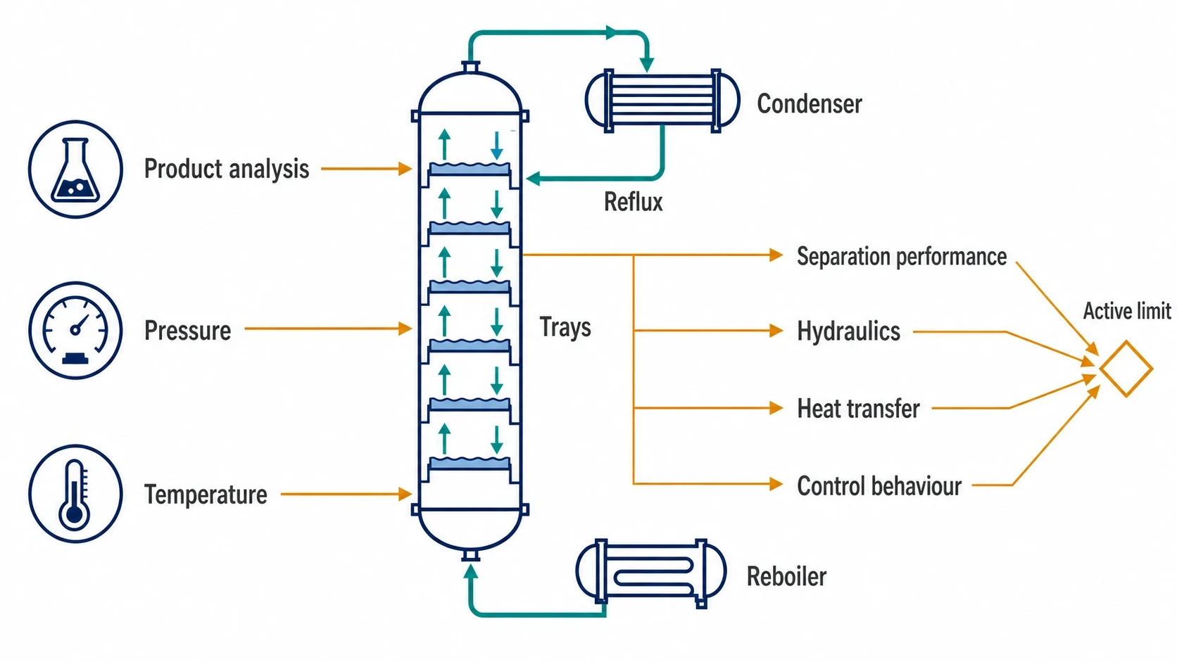
A column has a practical operating window bounded by separation performance, hydraulics, heat-transfer capacity and control behaviour. Optimisation identifies the active limit rather than assuming reflux is the root cause.
| Observed symptom | Likely constraint to investigate | Utility consequence |
|---|---|---|
| High steam use with comfortable product quality | Excess reflux, excess boil-up, conservative purity margin | Reboiler and condenser duties rise together |
| Distillate purity falls during throughput increase | Flooding, entrainment, inadequate reflux, condenser limitation | Operators often compensate with more reflux and steam |
| Bottoms quality drifts while steam rises | Reboiler fouling, steam-pressure variation, feed composition change | Higher steam flow may not provide proportional vapour generation |
| Column pressure rises in warm weather | Condenser area, cooling-water temperature, vent restriction | Higher pressure can increase reboiler temperature requirement |
| Large pressure drop across the column | Flooding, damaged trays, fouling, liquid maldistribution | Reduced capacity and poorer separation efficiency |
| Oscillating reflux and pressure | Poorly tuned controls, valve stiction, undersized control valves | Utility use becomes variable and product margin increases |
Tray flooding, downcomer backup, entrainment and weeping need different remedies. Flooding increases pressure drop and upsets separation because liquid cannot descend freely against rising vapour. Weeping occurs when vapour flow is too low to support liquid on a tray. Packed columns add concerns around liquid distribution, packing condition and maldistribution after turnarounds.
Column temperature is a useful operational signal, but not an independent measure of composition. A temperature controller can conceal changing composition if pressure changes, an analyser drifts or the feed contains additional components. Product analysis, pressure and temperature should be assessed together.
Remove heat-transfer penalties first
Fouling in reboilers and condensers often causes an apparently energy-hungry column. A fouled reboiler can require higher steam pressure or flow to achieve the same boil-up. A fouled condenser raises column pressure, changing relative volatility and increasing the required reboiler temperature.
The investigation should separate steam-side, process-side and control limitations. Steam-trap condition, non-condensable gases, condensate backup and inadequate venting can reduce heat transfer without appearing in a simplified model. On the condenser side, cooling-water fouling, air ingress, high cooling-water return temperature and restricted drainage need the same attention.
Cleaning an exchanger becomes an optimisation measure when restored heat transfer allows lower steam use, lower pressure or reduced reflux while maintaining the required separation.

Map every energy and material flow in your process with detailed heat and mass balance calculations — the foundation for any optimisation or design project.
Practical routes to lower steam and cooling demand
Optimise reflux and boil-up together
The first low-capital measure is a controlled test programme around the current operating point. Engineers should reduce reflux or reboiler duty in small planned steps while monitoring product quality, differential pressure, pressure stability and control-valve travel. The aim is to map the true operating margin.
Reflux should not be reduced until a feed-composition disturbance has passed through the column. Residence time, reflux-drum inventory and analyser delay can otherwise produce an optimistic result that disappears later in the shift.
A useful sequence is:
- Establish a stable baseline at normal throughput.
- Confirm analyser performance against laboratory results.
- Reduce reflux or boil-up by a defined increment.
- Wait for the column, receivers and analysers to reach a new steady condition.
- Record product quality, recovery, pressure profile and utility duty.
- Repeat only while the column retains its required operating margin.
- Set a controlled operating envelope rather than a single aggressive target.
Use feed and product heat recovery
A column’s overhead and bottoms streams often contain recoverable heat. Feed preheating with a hot bottoms stream can reduce reboiler duty, provided exchanger temperature approaches, fouling risk and controllability remain acceptable. Condensate return can also reduce boiler demand where the site steam system and condensate quality permit it.
Heat integration must preserve the column’s temperature driving force. An exchanger network that transfers heat on paper but leaves inadequate temperature difference at the reboiler or condenser will create control problems. Pinch analysis and a validated heat and mass balance help identify exchanges achievable across expected seasonal and campaign conditions.
Consider advanced modifications only after resolving the base case
Mechanical and process changes can deliver larger reductions, but should follow optimisation of the existing column. The 2025 review in Separation and Purification Technology reports 20% to 60% energy savings and 10% to 30% cost savings as typical across distillation-intensification strategies. These are broad benchmarks for suitable applications, not a promised outcome from a routine operating adjustment.
Potential measures include:
- Vapour recompression, where compressor work upgrades overhead vapour for reboiler heating.
- Mechanical vapour recompression, where the column’s vapour becomes a heat source after compression.
- Heat-pump-assisted distillation, where the temperature gap and electricity economics support duty transfer.
- Dividing-wall columns, which can reduce repeated separation duty in suitable multi-component services.
- Side reboilers, side condensers or side draws, where they match the separation and heat-integration target.
- Higher-efficiency trays or structured packing, where a hydraulic survey confirms that internals limit capacity or separation.
These measures change controllability as well as energy demand. Vapour recompression introduces compressor availability and anti-surge requirements. Dividing-wall columns can have narrower operating flexibility. A project team should assess production campaigns, turndown, start-up, shutdown and upset recovery before selecting a configuration.
Protect safety, product quality and operability
Treat pressure optimisation as a managed change
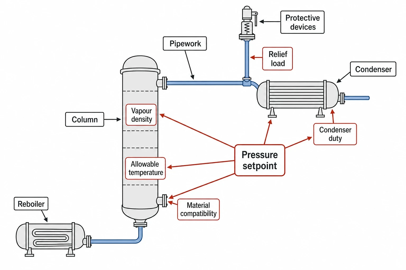
An altered pressure setpoint affects relief loads, vapour density, condenser performance, allowable temperature and material compatibility. UK sites should subject the change to formal management of change, including process-safety review, operating-procedure updates and assessment of alarms, trips and relief protection.
The Pressure Equipment (Safety) Regulations 2016 apply to pressure equipment and assemblies placed on the market or put into service with maximum allowable pressure above 0.5 bar. A revamp that adds or replaces pressure equipment needs an appropriate assessment of this scope and the relevant design and conformity requirements.
For equipment in use, the Pressure Systems Safety Regulations 2000 place duties on users of qualifying pressure systems. HSE guidance states that users must know safe operating limits and ensure that a suitable written scheme of examination is in place. A new operating envelope should therefore be checked against the column, reboiler, condenser, associated pipework and protective devices, not only the control-system setpoint.
Keep specification and recovery in the decision
Steam savings have little value if off-specification material increases reprocessing, disposal or downstream purification duty. The operating case should report:
- Product purity and contaminant limits.
- Component recovery and loss to vent, purge or waste.
- Steam, electricity and cooling duty per tonne of on-specification product.
- Throughput and campaign duration.
- Column pressure drop and available hydraulic margin.
- Frequency and severity of operator intervention.
- Boiler fuel and associated CO₂e, using the site’s approved emissions methodology.
ISO 50001:2018 provides a suitable management-system context because it focuses on continual improvement of energy performance. The best column target is a controlled, documented operating standard with defined data quality, process limits and review triggers.
What a successful distillation column optimisation programme delivers
A successful programme does more than reduce a steam-flow reading. It provides a validated explanation of utility demand, identifies the constraint governing throughput or purity, and sets a safe operating envelope that production teams can maintain.
For many established columns, the first gains come from correcting the model, restoring heat transfer, improving analyser confidence and reducing unnecessary reflux margin. These measures can avoid major capital expenditure while revealing whether heat integration, vapour recompression or an internal retrofit has a credible technical case.
The final recommendation should state the expected utility change, product-quality and hydraulic margins, safety actions, required instrumentation and any dependency on feed conditions.
This article reflects the independent analysis and editorial opinion of EnerTherm Engineering. Product names, trademarks, and brands mentioned belong to their respective owners. EnerTherm Engineering is not affiliated with, endorsed by, or a licensee of any third-party software or product mentioned unless explicitly stated.

Technical Manager — EnerTherm Engineering
John Naranjo is Technical Manager at EnerTherm Engineering, bringing specialist expertise in chemical and environmental engineering. He recently led the implementation of Omni Vision, EnerTherm's real-time energy and utility monitoring platform. He holds an MSc in Environmental Engineering from the University of Huelva and a BSc in Chemical Engineering, with memberships in both the Energy Institute and IChemE.
