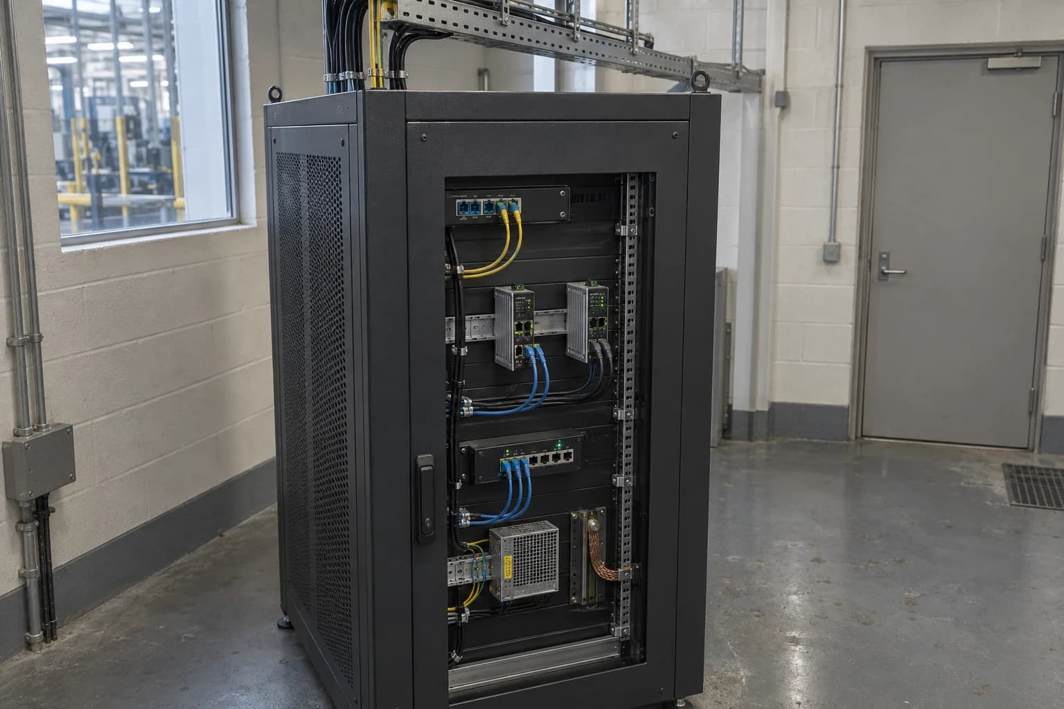
How Modbus Data Reaches the Cloud Without Writing to PLCs
Read-only Modbus data crosses a DMZ into encrypted cloud analytics without PLC writes.
A Modbus-to-cloud data transmission architecture collects selected register values from industrial equipment, moves them through segmented OT networks, and publishes them to cloud analytics without sending write commands to the PLC.
That distinction matters on a live production site. A PLC may control a burner sequence, pasteuriser, compressor, boiler, packaging line or water-treatment skid. The cloud platform needs production, utility and status data, but it has no reason to alter a setpoint, force an output or change a recipe. A correctly designed connection keeps those responsibilities separate.
For manufacturers, this provides useful operational data without changing the existing control programme. Utility readings can be related to lines, shifts, products and batches. Engineers can investigate energy intensity, abnormal consumption and equipment behaviour from centralised data, while the control system retains authority over the process.
The technical challenge is that Modbus was designed for industrial interoperability, not internet-facing cloud exchange. Modbus TCP can expose useful registers, but legacy implementations often lack the authentication, encryption and access control expected at an IT/OT boundary. The solution is not to expose a PLC to the internet. It is to collect only the required information, enforce a no-write policy, segment the path, and apply security controls before data leaves the plant.
What read-only Modbus to cloud data transmission means
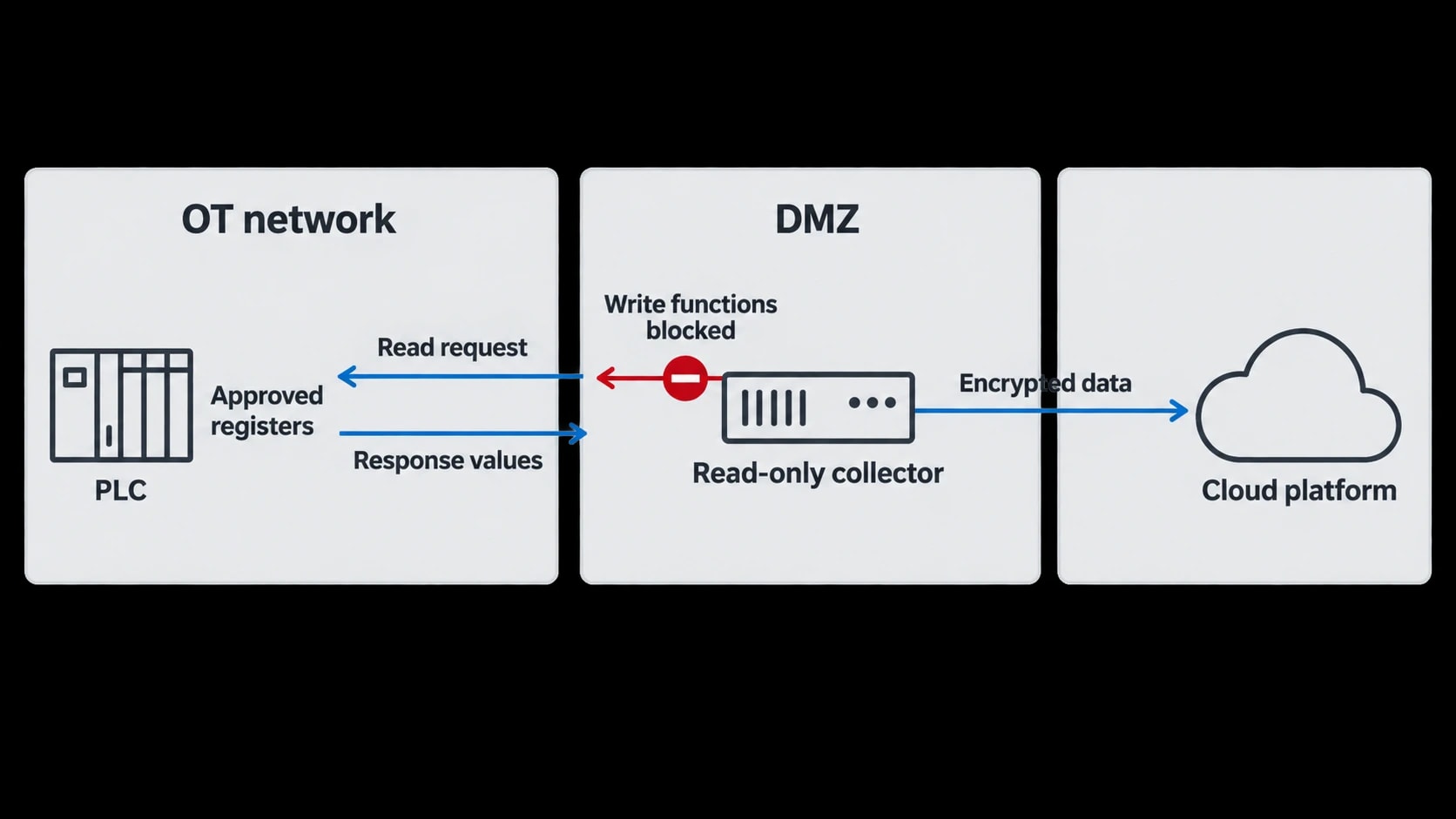
Read-only has a precise operational meaning: the data collection system may obtain values from agreed Modbus addresses, but it cannot issue a command that changes a device state, parameter or configuration.
Reading registers without changing plant control
Modbus supports several data types, including coils, discrete inputs, input registers and holding registers. A cloud data project normally starts with a register list agreed by the controls engineer, process owner and equipment supplier where appropriate.
The list might include:
- Electricity meter kWh, kW, voltage and power factor
- Steam pressure, temperature, flow and totalised consumption
- Compressed-air flow, pressure and compressor run status
- Boiler fuel use and combustion measurements
- Production count, batch identifier, line state and planned downtime flag
- Alarm status, subject to a clear interpretation of each code
A data collector can poll approved addresses using Modbus read functions. It should block Modbus functions that can alter PLC or device data, including commands to write coils or registers. The access rule needs enforcement in the collector configuration and network architecture. A configuration screen labelled “read-only” is useful, but it should not be the sole safeguard.
Read-only collection also means that engineers do not modify ladder logic, function blocks, recipes or HMI screens merely to supply cloud data. Existing PLC logic remains intact. If a facility needs a new calculation or production-context signal, it should first assess whether a suitable tag already exists. Where a new tag is necessary, the site’s change-control process should govern it.
Passive listening and active read polling are different
“Listening mode” can describe two different approaches.
A passive network monitor receives a copy of traffic through a network tap or switch-port mirroring. It does not initiate Modbus requests. This can support asset discovery, protocol visibility and verification, although it sees only values that another system already requests.
A read-only Modbus collector initiates approved read requests and receives responses. It generates traffic, but does not write to the PLC. This is often the practical choice when no supervisory system already polls the required registers.
Both approaches need engineering discipline. A new Modbus client can affect a lightly specified or heavily loaded legacy device if polling is too frequent, register blocks are poorly chosen or connection handling is unsuitable. The commissioning plan should define polling intervals, maximum request size, timeout behaviour, retry limits and the response to a lost connection.
The cloud does not need every PLC tag
Sending thousands of unexamined tags to a cloud platform produces cost, complexity and noise. The useful dataset is usually smaller and purposeful.
For energy intelligence, a concise model may combine utility measurements with production context:
| Data group | Typical values | Operational use |
|---|---|---|
| Electricity | kW, kWh, voltage, power factor | Demand analysis and energy per unit |
| Thermal utilities | Gas, steam flow, steam pressure, boiler status | Fuel allocation and steam-loss investigation |
| Compressed air | Flow, pressure, compressor state | Leak identification and compressor review |
| Water and effluent | Flow, totaliser, conductivity where available | Consumption profiling and process comparison |
| Production context | Batch, line state, product code, count | Energy per batch, cost per tonne and idle-load analysis |
A tag register should record the Modbus address, data type, byte order, engineering unit, scale factor, source equipment, poll rate, owner and intended calculation. It should also identify whether a value is process-critical, personal data, commercially sensitive or unsuitable for export.

Omni Vision delivers turnkey utility metering, CO2 tracking, and AI-powered production KPI intelligence — giving you real-time dashboards and actionable insights across your entire facility.
Where the Purdue Model places the connection
The Purdue Model provides a useful way to discuss the boundary between plant control and business or cloud systems. It is an architectural reference model, not a substitute for a site-specific risk assessment.
A common interpretation places field instruments and actuators at Level 0, PLCs and other basic control devices at Level 1, and operator workstations and supervisory control at Level 2. Site operations systems sit at Level 3. A Level 3.5 industrial demilitarised zone, commonly called an industrial DMZ, separates operations systems from business networks and external services.
Keep cloud routes away from Levels 0 to 2
A cloud service should not communicate directly with a PLC at Level 1 or an HMI at Level 2. That creates an unnecessary route from a less trusted environment towards the process.
Instead, the collection path should terminate locally. A gateway, historian interface or approved data collector obtains the required values inside the OT environment and prepares a constrained dataset for onward transfer. The IT/OT boundary then controls what can pass towards the industrial DMZ and cloud service.
This reduces the systems able to address the PLC network and makes exported data easier to inspect, log and govern.
The industrial DMZ is a control point, not a shortcut
The Level 3.5 DMZ provides a place for services that must communicate across trust boundaries, such as brokers, proxies, transfer services and monitored integration hosts. It should not become an unrestricted bridge between enterprise IT and control networks.
A typical design permits the collector or an OT-side intermediary to send a tightly defined telemetry stream towards a DMZ service. A separate cloud-facing component forwards that stream through an approved outbound connection. Firewall rules should allow only the named source, destination, protocol and port required by the design.
The UK National Cyber Security Centre recommends segmentation and segregation where device or protocol protections are limited. It also advises that a data diode can provide hardware-enforced directionality, while warning that a diode alone does not provide all the security functions of a Cross Domain solution.
When a data diode is appropriate
A unidirectional gateway, often called a data diode, physically enforces flow in one direction. In a high-consequence setting, this can provide stronger assurance that an external system cannot create a return network path to the control environment.
A diode suits architectures that strictly export data, including selected meter readings, production records and security telemetry. It may require a relay mechanism because many common application protocols assume a two-way session.
An outbound encrypted connection through a firewall can still be appropriate where the site risk assessment permits it. TCP and TLS sessions contain return traffic for session establishment and acknowledgement, so this should not be described as physically unidirectional. The design objective is controlled outbound application access, with no cloud-initiated path to the PLC network.
How legacy Modbus data is secured for cloud use
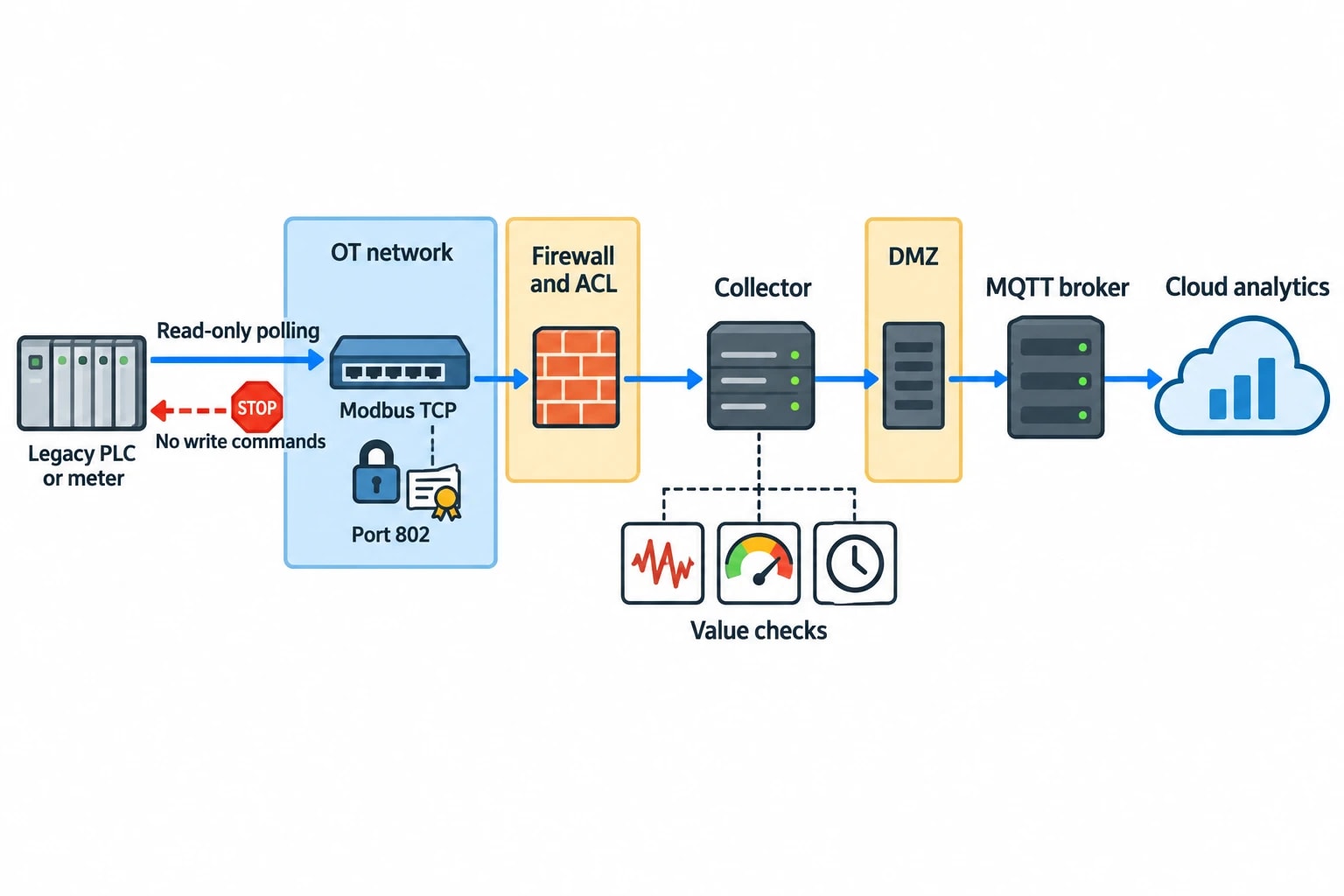
Modbus TCP remains common because it is simple, widely supported and easy to troubleshoot. Its original protocol design should shape the architecture.
Protect the Modbus side locally
The Modbus Organisation specifies a Modbus Security protocol that combines Modbus with Transport Layer Security, X.509 certificates and message-integrity protection. It uses port 802. Many established PLCs, meters and controllers do not support that option, so a plant cannot assume that a legacy Modbus TCP device provides encrypted or authenticated communication.
For those devices, protective controls belong around the protocol:
- Place the device on a segregated OT network.
- Restrict the collector to approved IP addresses and Modbus read operations.
- Prevent direct routes from enterprise IT or the public internet to the device.
- Use managed switches, firewalls and access-control lists to limit the communication path.
- Monitor unexpected clients, protocol requests and configuration changes.
- Maintain an asset inventory that includes device model, firmware, owner and support status.
The collector should validate data before forwarding it. This includes rejecting malformed values, handling communication loss clearly, applying sensible value-range checks, and marking a value as stale rather than silently presenting it as current.
Wrap telemetry in a secure protocol at the boundary
Once the collector has received and normalised the Modbus values, it can publish telemetry through a protocol suited to the DMZ and cloud path.
MQTT is often used for telemetry because a publisher can send topic-based messages to a broker. The security outcome depends on deployment choices. Encryption in transit, certificate validation, client authentication, topic-level authorisation and restrictive broker permissions must be configured deliberately.
OPC UA offers a different path where structured information modelling and interoperable industrial data exchange are required. Its security model includes application authentication, encryption, message signing and auditing capabilities. Its use does not automatically make an architecture safe. A site still needs certificate management, suitable security policies, least-privilege permissions and a segmented network.
Neither MQTT nor OPC UA changes the read-only rule at the PLC. They protect or structure data after collection. The no-write policy must remain enforced at the Modbus interface and through OT network controls.
Preserve context and auditability
Cloud analytics depends on trustworthy context. A timestamp without a source identifier, quality flag or unit can produce misleading results. The exported message should retain:
- Source asset and measurement point
- UTC timestamp and local time context where operational reporting needs it
- Engineering unit and scale
- Data-quality status
- Sequence number or another method to identify gaps and duplication
- Batch, product or line context where available
- Collection-system audit events, including communication failures
This matters when an energy manager investigates a rise in steam consumption. A useful dataset can show whether the increase occurred during production, sanitation, warm-up, idle running or a communications fault. A raw value alone cannot do that.

Track energy consumption, emissions, and process parameters with seamless PLC/SCADA integration via Modbus, OPC-UA, and MQTT protocols.
Standards and regulation shape the design decisions
Industrial connectivity now receives closer attention from regulators, product manufacturers and cybersecurity teams. Legal scope differs between a factory operator, a gateway supplier and a cloud service provider, so organisations should not treat one regulation as a universal compliance checklist.
ISO/IEC 27001:2022 provides the management framework
ISO/IEC 27001:2022 specifies requirements for an information security management system. For a Modbus-to-cloud project, it supports a disciplined approach to asset ownership, risk assessment, access control, supplier management, incident handling and evidence.
The standard does not prescribe a network drawing or make an old Modbus device secure. It helps an organisation govern decisions around that device. Useful evidence includes the approved data-flow diagram, register list, firewall rules, certificate ownership, backup configuration, commissioning records and periodic access reviews.
IEC 62443-4-2 focuses on component security requirements
IEC 62443-4-2:2019 sets technical security requirements for industrial automation and control system components. Its seven foundational requirements cover identification and authentication control, use control, system integrity, data confidentiality, restricted data flow, timely response to events and resource availability.
For a gateway or data-collection component, these principles translate into practical questions:
- Which client identities can connect?
- Which functions can each identity use?
- Can an administrator change the read-only configuration?
- Are certificates, credentials and software updates managed?
- Does the component log failed connection attempts and configuration changes?
- Can it continue operating safely through a cloud outage?
- Does the architecture restrict data flow to the required path?
A legacy PLC may be unable to meet modern component requirements itself. Segmentation, constrained gateways and compensating controls can reduce exposure while a site plans longer-term equipment renewal.
UK PSTI and the EU Cyber Resilience Act have different scope
The UK Product Security and Telecommunications Infrastructure Act 2022 and the Product Security and Telecommunications Infrastructure (Security Requirements for Relevant Connectable Products) Regulations 2023 apply to in-scope consumer connectable products. The regime has applied since 29 April 2024. It is not a direct operational rulebook for an industrial PLC installation, but it illustrates the direction of product-security regulation: credential hygiene, vulnerability reporting and transparent security-update periods.
The EU Cyber Resilience Act is Regulation (EU) 2024/2847 on horizontal cybersecurity requirements for products with digital elements. It entered into force on 10 December 2024. Its reporting obligations began on 11 September 2026, while full application is scheduled for 11 December 2027.
For manufacturers placing relevant gateways, software or other digital products on the EU market, secure development, vulnerability handling, update support and documented product security will become material obligations. For plant operators, these requirements strengthen the case for asking suppliers about support life, security updates, vulnerability disclosure and evidence of secure configuration.
A commissioning method that protects PLC stability
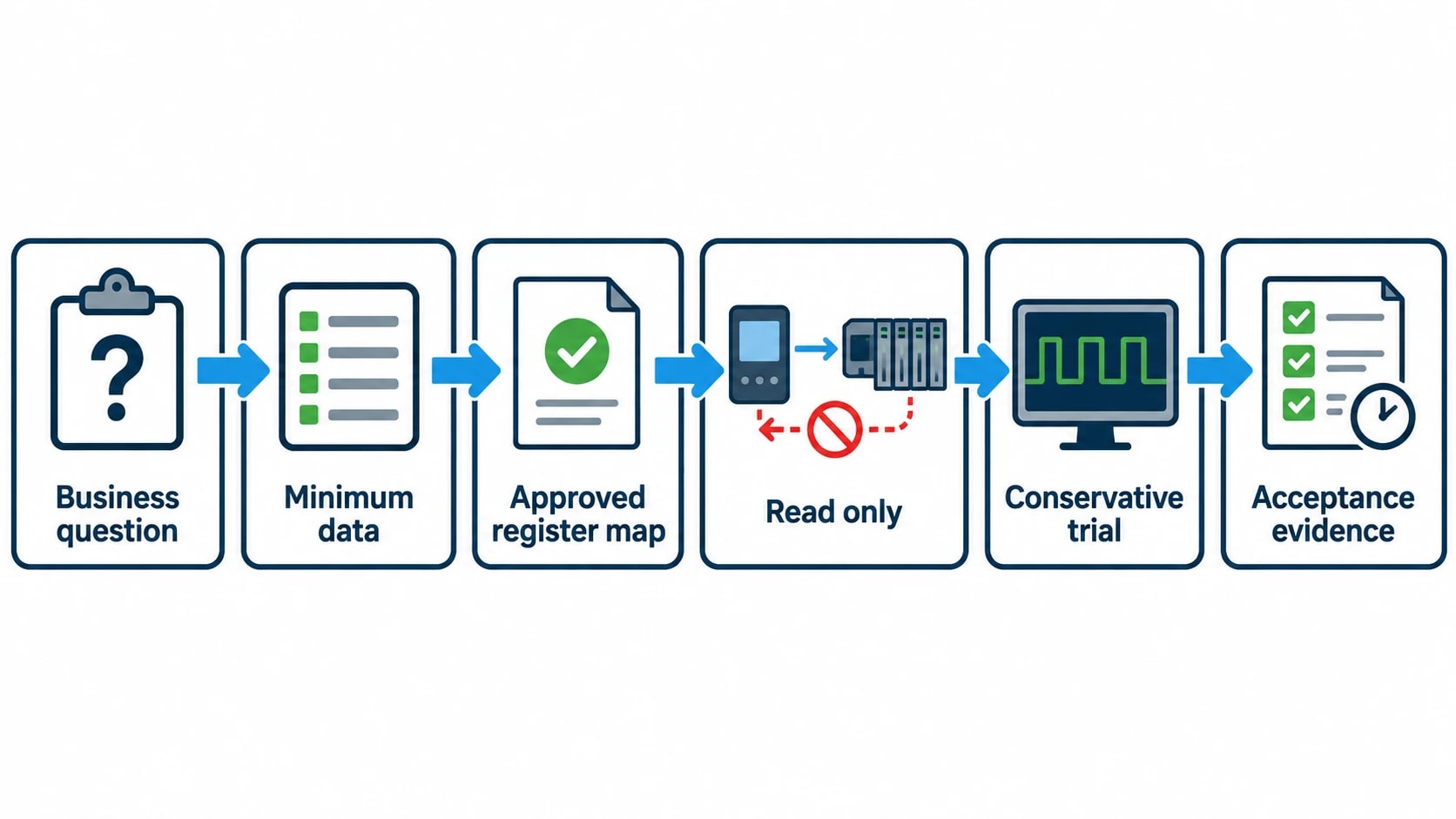
A safe integration should be treated as a controlled engineering change, even where no PLC code changes are planned.
1. Define the value and the boundary
Start with the business question. A facility may want to identify compressed-air leakage, allocate gas consumption to a process line, report Scope 1 and Scope 2 emissions, or compare energy per batch.
Then define the minimum data required. This keeps the register list, network exposure and cloud dataset proportionate to the purpose.
2. Survey the existing OT system
Document PLCs, meters, serial converters, switches, existing Modbus clients, IP addresses, firmware, communication loads and vendor support restrictions. Review the network drawing with the controls engineer before connecting a collector.
This survey often identifies existing historian interfaces, spare Ethernet ports, unsupported devices or vendor restrictions that affect the preferred approach.
3. Agree the read-only control set
The commissioning pack should include an approved register map, permitted read operations, poll intervals, timeout values and a written prohibition on writes. Restrict configuration access to named administrators. Record the collector software version, configuration checksum and firewall policy.
Where passive monitoring is used, test the mirror or tap configuration and confirm that it cannot transmit traffic into the production segment.
4. Test outside the production window where possible
A representative test environment is preferable. Where the live plant is the only available environment, begin with a small number of tags and conservative polling rates. Controls engineers should observe PLC communications, scan-time trends, alarms and device diagnostics during the trial.
The acceptance test should demonstrate that the platform receives the expected readings, communication loss produces a visible quality status, and no prohibited Modbus function reaches the device. Firewall logs and gateway audit logs should form part of the evidence.
5. Operate and review the connection
Cloud connectivity is an operating service, not a one-off installation. Review device support status, certificates, access rights, firewall rules and data quality on a planned basis. Investigate new Modbus clients, unexpected traffic volumes and failed authentication events promptly.
Turning read-only data into manufacturing insight
Read-only connectivity gives an energy platform access to operating evidence without taking control of the plant. That is especially valuable where production equipment remains in service for decades.
Within the Omni Vision Energy Intelligence Platform, selected utility and production values can be brought together for central analysis. The resulting view can relate electricity, gas, water, steam, compressed air and oil to lines, shifts and batches. It can also support production-linked measures such as energy per unit, cost per tonne and energy per batch.
The quality of those insights depends on the foundation. A clear tag model, controlled Modbus reads, an OT-to-DMZ boundary, secure cloud transport and maintained evidence give engineers data they can trust. The PLC continues to run the process; the cloud provides information for operators and building-management systems to act on during validated change windows.
This article reflects the independent analysis and editorial opinion of EnerTherm Engineering. Product names, trademarks, and brands mentioned belong to their respective owners. EnerTherm Engineering is not affiliated with, endorsed by, or a licensee of any third-party software or product mentioned unless explicitly stated.

Simulation Engineer — EnerTherm Engineering
Rajesh Sekar is a Simulation Engineer at EnerTherm Engineering, specialising in computational fluid dynamics (CFD), finite element analysis (FEA), and thermal process simulation. He holds a degree from Cranfield University and brings extensive experience in simulation-based product development from the automotive, aerospace, and energy sectors.
