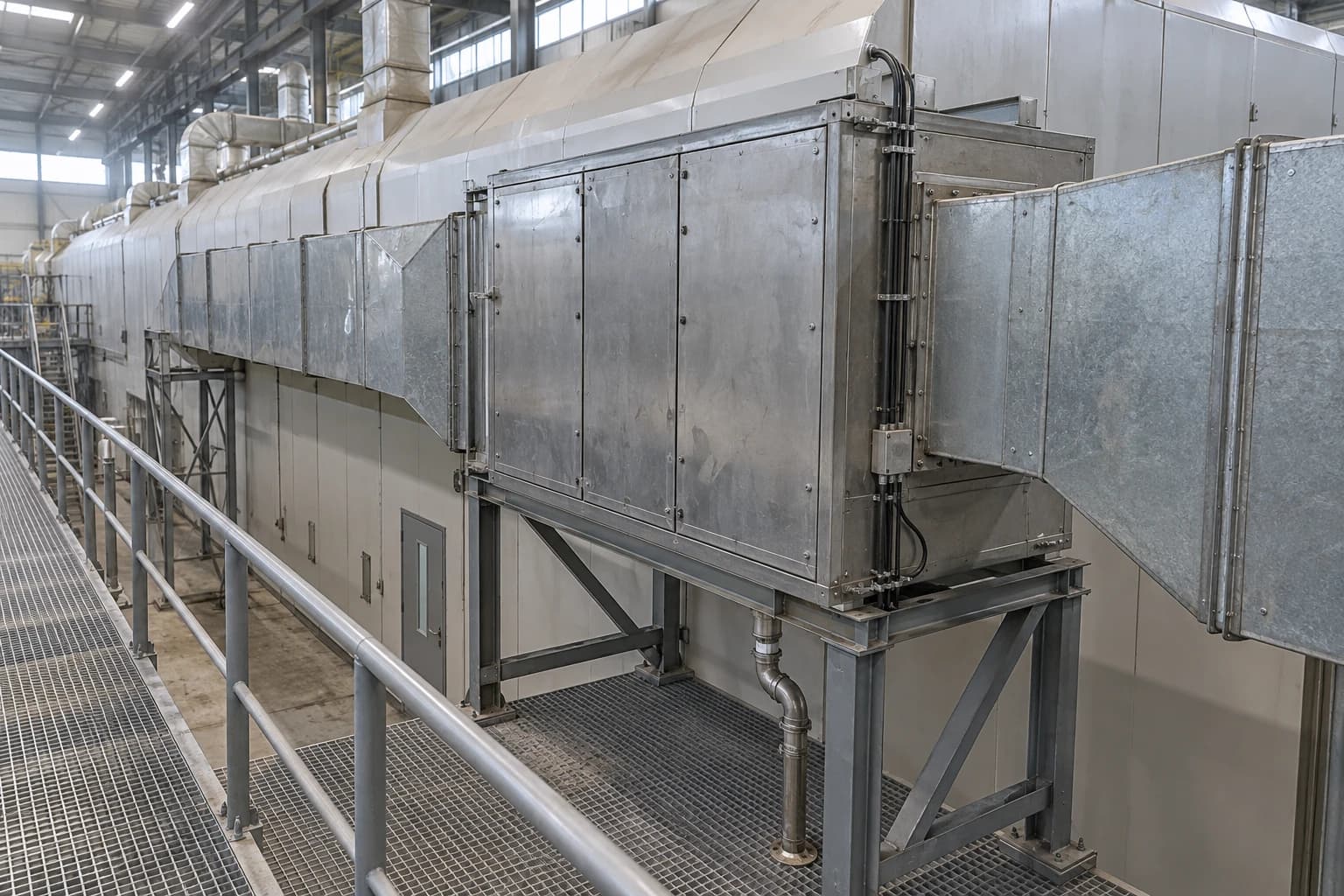
How Paper Mills Recover Heat from Dryer Hood Exhaust
EU BREF data puts dryer-hood exhaust at 80-85 °C and 140-160 g H₂O/kg dry air
A paper-machine dryer hood heat-recovery system transfers sensible and latent heat from hot, moisture-laden exhaust air to dryer supply air and suitable water streams, cutting the external steam needed to meet target temperatures.
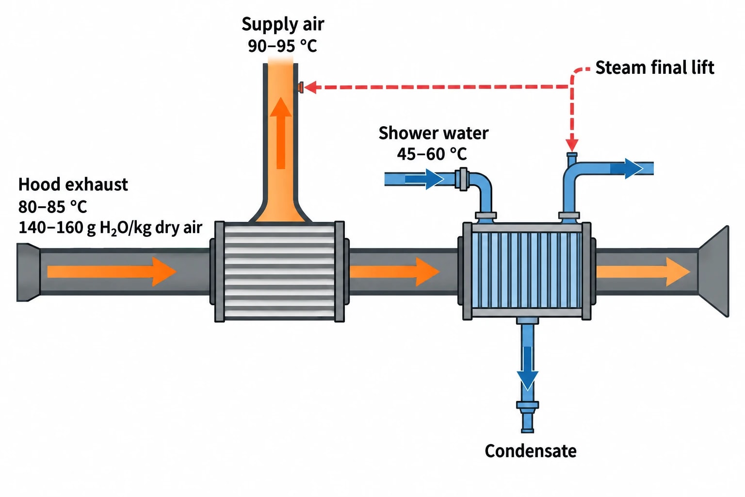
The opportunity is substantial because the dryer section removes a large water load from the sheet. The EU Pulp, Paper and Board BREF reports that paper commonly leaves the dryer section at 90 to 95% dryness, while about 1 to 1.5 m³ of moisture per tonne of paper is exhausted. Typical hood exhaust is quoted at 80 to 85 °C and 140 to 160 g H₂O/kg dry air.
That exhaust stream contains sensible heat in the air and water vapour, plus latent heat released when vapour condenses. Recovering it reduces steam use, but the dryer hood remains a drying system first. It must remove evaporated water evenly, maintain the required hood pressure and humidity, and protect sheet runnability.
Why dryer section heat recovery matters in a paper mill
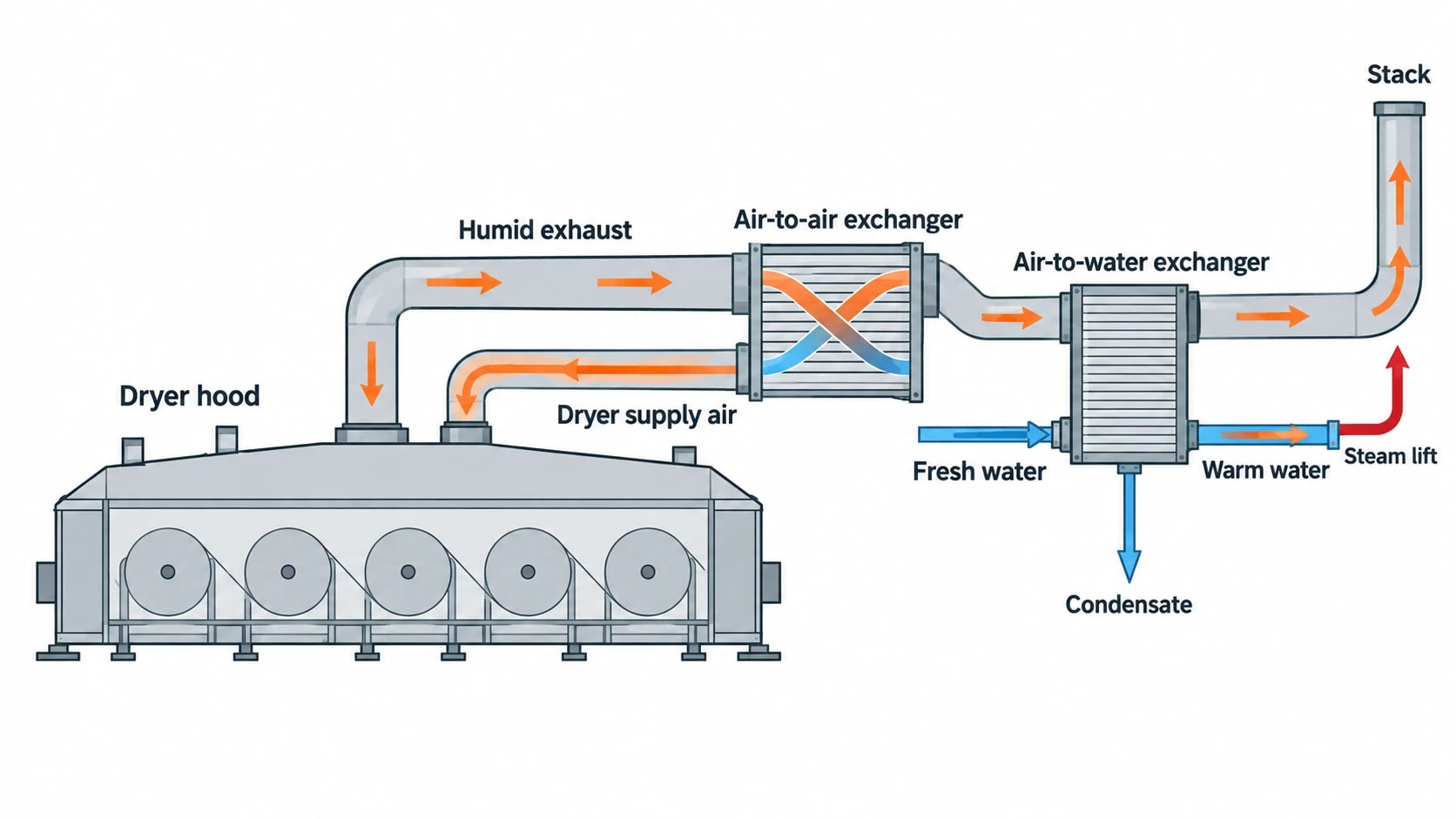
Steam-heated dryer cylinders evaporate moisture after the press section has removed as much water as practical. The hood collects moist air around those cylinders, and exhaust fans remove it from the machine.
Nearly all drying energy initially leaves the dryer section in this humid exhaust stream. A recovery system returns part of that energy to the process before the exhaust reaches the stack.
The usual sequence follows temperature value. Heat first transfers to incoming dryer supply air, the hottest practical heat sink. Lower-temperature heat then serves water duties such as fresh water, shower water, white water, wire-pit water or machine-hall ventilation loops.
This sequence matters. Sending the best part of the hood exhaust directly to low-temperature water can leave insufficient temperature difference for supply-air heating. Steam then fills a duty that the exhaust could have covered.
The heat and moisture balance behind the system
Dryer hood exhaust has high absolute humidity because it has collected vapour from the paper web. As the exhaust cools in a heat exchanger, its temperature falls towards the dew point and water starts to condense on the exhaust side.
Condensation releases latent heat. This is why humid-air recovery can perform well even where the apparent dry-bulb temperature difference is modest.
The BREF describes a conventional sequence in which exhaust heat first warms incoming dryer supply air, then incoming fresh water. Some mills recover additional heat to wire-pit water or a ventilation circulation-water loop. Steam provides the final temperature lift where necessary.
Recovery is constrained by drying performance
Hood heat recovery cannot operate as a separate utility plant. The hood, pocket ventilation, exhaust fans, supply fans and dryer-cylinder steam system interact continuously.
TAPPI TIP 0404-24 identifies paper-machine hood and air-system design, operation, performance evaluation and troubleshooting as linked tasks. The practical objective is controlled removal of evaporated water with uniform drying across the web. Recovery controls must support it.
A heat exchanger retrofit can create problems when it:
- Adds excessive air-side pressure drop and limits exhaust flow.
- Alters the supply-to-exhaust balance and changes hood pressure.
- Causes unsuitable supply-air temperature or humidity.
- Restricts access for cleaning and inspection.
- Introduces poorly managed condensate into ducts or drains.

Pinch analysis identifies the thermodynamic minimum energy requirement of your process — then designs the heat exchanger network to achieve it.
Dryer section heat recovery paper mill equipment options
Equipment choice depends on exhaust condition, available sinks, contamination risk, space, pressure-drop allowance and the value of recovered heat. A survey should establish operating conditions across the grade range before hardware is selected.
| Recovery equipment | Typical duty | Main benefit | Design concern |
|---|---|---|---|
| Air-to-air plate heat exchanger | Preheats incoming hood supply air | Places recovered heat into the highest-temperature practical sink | Exhaust-side fouling, condensate drainage and fan pressure drop |
| Air-to-water coil | Heats fresh, process, shower or circulation water | Connects exhaust heat to several plant water demands | Water-side fouling, freezing exposure and control-valve authority |
| Combined plate and tube recovery stack | Supports staged air and water duties | Allows temperature-matched recovery in a compact arrangement | Distribution between parallel stacks and maintainability |
| Direct-contact scrubber or trickling tower | Recovers low-temperature latent heat while cooling exhaust | Can capture heat beyond dry surface exchange | Water treatment, carry-over control, drainage and plume implications |
Plate air-to-air exchangers
A plate heat exchanger transfers heat from hood exhaust to incoming outdoor or machine-room air without mixing the streams. It normally occupies the first position in a recovery train because dryer supply air can accept high-grade heat.
The heat exchanger needs effective condensate collection on the exhaust side. Vapour condensing inside it improves heat transfer, but standing water encourages deposits and can obstruct drainage. Designers should allow access to clean air passages and inspect seals.
Pressure loss needs early attention. If an existing exhaust fan cannot overcome added resistance at peak production, the mill may lose exhaust capacity when the sheet carries its highest evaporation load.
Air-to-water coils and recovery loops
Air-to-water coils transfer heat from exhaust air into a closed loop or directly into a suitable water stream. They are useful once supply-air heating has taken the highest-temperature recovery duty.
The heated-water destination needs a stable, useful demand. Fresh-water preheating, shower-water heating and ventilation-water loops are common candidates. An intermittent duty can leave exhaust heat stranded during normal production.
Water chemistry and cleanliness determine the practical arrangement. A separate circulating loop and secondary heat exchanger may protect a sensitive process-water circuit from fouling, but each additional heat exchanger reduces the available temperature difference. The design should weigh that thermal penalty against maintenance and contamination risk.
Direct-contact scrubbers
A wet scrubber or trickling tower places water in direct contact with humid exhaust. It can recover low-temperature heat by condensing water vapour into the circulating liquid.
This arrangement can suit Yankee hood exhaust and other cases with an available low-temperature water sink. Commission Implementing Decision 2014/687/EU identifies heat recovery from Yankee hood exhaust with a trickling tower among energy-efficiency techniques for relevant paper and board activities.
The water circuit needs disciplined operation. Mills must manage solids, microbiological growth, scaling, droplet carry-over and the quality of recovered condensate or bleed stream. A direct-contact system should feed only a water circuit that can accept its water-quality characteristics.
How pinch analysis improves dryer hood heat recovery
Pinch analysis turns individual heat-exchanger opportunities into a heat-recovery plan. For a paper-machine dryer section, it tests hood exhaust against genuine heat sinks, including their temperatures, flow rates, operating hours and cleanliness constraints.
It prevents a common retrofit error: installing a heat exchanger around the most visible hot exhaust stream without checking whether recovered heat has displaced steam or merely warmed a stream beyond its useful temperature.
Build the data set from measured production conditions
A useful study starts with field data, not nameplate information. The minimum data set should include:
- Exhaust-air flow, temperature, absolute humidity and static pressure.
- Supply-air flow, temperature, humidity and fan operating point.
- Paper grade, basis weight, production rate and final dryness.
- Dryer-cylinder steam pressures, condensate flows and relevant steam use.
- Water-stream temperatures, flow rates, required outlet temperatures and seasonal availability.
- Heat-exchanger differential pressure, fouling history and cleaning intervals.
- Outdoor-air conditions and ventilation loads during representative weather.
Absolute humidity is particularly important. Dry-bulb temperature alone cannot quantify latent heat available from the exhaust or predict when condensation will occur.
Production conditions should cover more than one stable operating point. Grade changes, slower running, wet-end changes, felt condition and seasonal outdoor air alter the balance. A network sized from one favourable test may underperform for much of the year.
Match heat sources and sinks by temperature
The first target is normally hood supply air. It requires a comparatively high outlet temperature and operates whenever the dryer section runs. The BREF gives an example of supply air subsequently raised to 90 to 95 °C with steam after recovery.
Next come water duties that can use lower-grade energy. The BREF describes shower water heated to 45 to 60 °C with steam after upstream recovery. Recovery should raise a stream as far as sensible, then steam should provide the final lift only where the process needs it.
A pinch study can expose competing uses for the same heat. A water loop may appear attractive in winter because machine-hall heating demand is high, but that duty may disappear in warmer months. The annual case therefore depends on the operating calendar, not a single winter calculation.
Protect the temperature difference
Heat transfer requires a usable temperature driving force throughout the heat exchanger. Designers set a minimum approach temperature based on heat-exchanger type, fouling allowance, flow control and economic trade-off.
A very small approach can increase surface area, pressure drop and cleaning burden. An overly large approach leaves recoverable heat unused. The appropriate value is project-specific and should be evaluated against steam price, electricity demand from fans and pumps, maintenance access, and expected heat-exchanger cleanliness.

Pinch analysis identifies the thermodynamic minimum energy requirement of your process — then designs the heat exchanger network to achieve it.
Controls that preserve sheet drying and runnability
A recovery plant should follow the air system rather than forcing the hood to follow the recovery plant. The primary control task remains stable removal of vapour from the dryer section.
Measure the variables that govern performance
The control system needs reliable measurements at the hood, recovery train and heat sinks. Useful signals include exhaust temperature, absolute humidity or dew point, supply-air temperature, exhaust and supply fan flow, hood pressure, heat-exchanger differential pressure, water flow and water temperatures.
Trend data should be reviewed against production rate and grade. A drop in recovered heat may indicate lower evaporation load, blocked heat-transfer surfaces, failed dampers, poor water distribution or an instrument fault.
Differential pressure across each air-side heat exchanger is an early warning indicator. Increasing pressure drop can indicate fouling, while an unexpected fall may indicate bypassing, leakage or a damper problem.
Use bypasses and staged control
A controlled bypass around a recovery heat exchanger gives operators a way to protect hood conditions during start-up, upset conditions and grade changes. Water-side control valves should maintain useful outlet temperatures without causing unstable air temperatures or excessive coil cooling.
Freeze protection requires particular care where outdoor air meets water-filled coils. The design should include appropriate drainage, frost protection and safe failure positions for dampers and valves.
Condensate drains must remain effective across the operating range. Poor drainage reduces heat transfer and risks water carry-over into ductwork.
A practical implementation sequence for paper mills
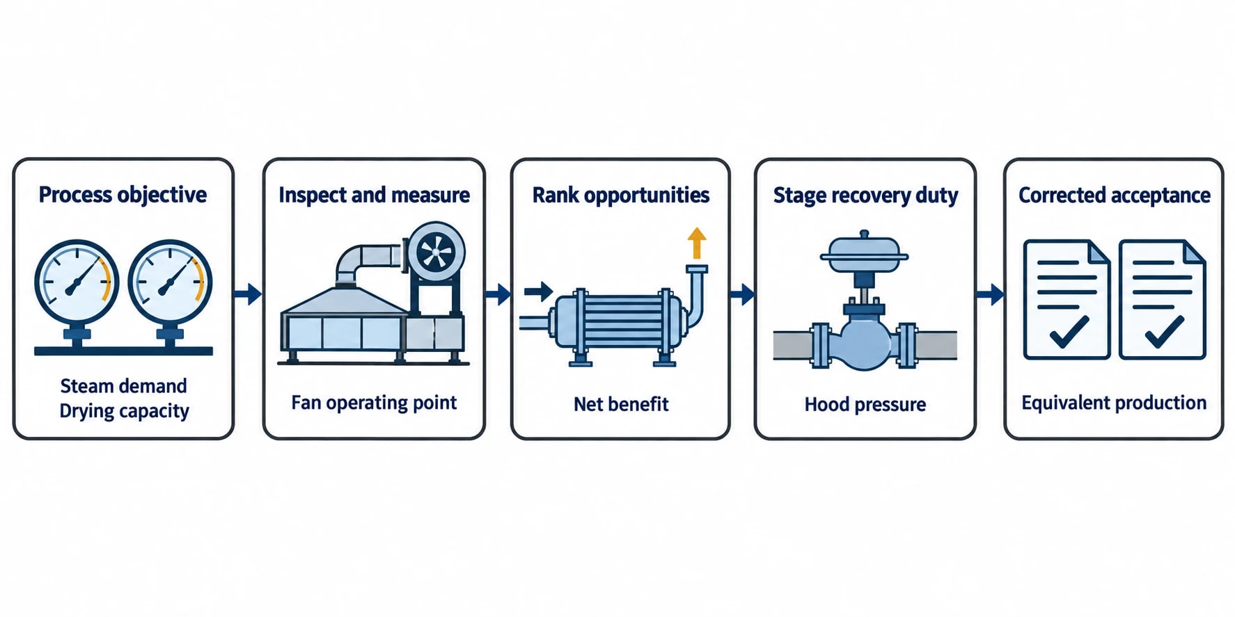
A successful retrofit starts with a defined process objective: reduce steam consumption while maintaining drying capacity, moisture profile and machine availability.
Start with the existing system
Inspect hoods, ducts, dampers, fans, seals, drains and existing recovery equipment. Measure the actual fan operating point rather than assuming the original fan curve still represents site performance.
Review recent grade changes and production constraints. An older recovery train may have been designed for a different basis-weight range, dryer loading or air system.
Develop and screen the heat-recovery cases
Rank opportunities by recovered heat that directly displaces steam, expected operating hours, required capital work and operational risk. A first-pass study should distinguish between heat that can be used reliably and heat available only under narrow ambient or production conditions.
Include electricity consumption. Extra fan pressure drop and pumping power reduce net benefit, particularly where the heat-exchanger train has accumulated fouling margins or restrictive duct geometry.
Commission against agreed machine limits
Commissioning should begin with baseline measurements at stable production. Introduce recovery duty in stages while checking hood pressure, exhaust humidity, supply-air conditions, cross-machine moisture profile, sheet breaks and steam demand.
The acceptance test should compare corrected performance under equivalent grade and production conditions. A lower steam flow during a different production run does not by itself prove a heat-recovery saving.
UK and EU BAT context for hood exhaust recovery
The EU Pulp, Paper and Board BREF identifies efficient exhaust-air heat recovery, careful process integration and pinch analysis as energy-efficiency measures for paper and board production. Commission Implementing Decision 2014/687/EU includes efficient exhaust-air recovery systems, heat recovery from axial blowers for dryer-hood supply air, and recovery from Yankee hood exhaust among relevant BAT techniques.
For UK mills, environmental permit conditions and regulator guidance determine site-specific BAT requirements. The Environment Agency describes BAT as covering the technology used and the way an installation is designed, built, maintained and operated.
A new heat exchanger alone does not deliver sustained performance. The mill needs an air balance that protects drying, temperature-matched heat sinks, clean heat-transfer surfaces, effective condensate management and controls that respond to changing machine conditions.
This article reflects the independent analysis and editorial opinion of EnerTherm Engineering. Product names, trademarks, and brands mentioned belong to their respective owners. EnerTherm Engineering is not affiliated with, endorsed by, or a licensee of any third-party software or product mentioned unless explicitly stated.

Managing Director — EnerTherm Engineering
Dr. François Pierrel is Managing Director of EnerTherm Engineering with over two decades of expertise in thermal design, heat transfer, and industrial energy optimisation. He holds a PhD in Heat Transfer from Cranfield University and a Post-Doctorate from Heriot-Watt University.
