How Pinch Analysis Cuts Carbon Capture Heat Demand
How waste heat integration can reduce the typical 2-3 GJ/tCO2 regeneration load
Pinch analysis is a process-integration method that identifies the minimum external heating and cooling required by matching heat sources and heat sinks across an industrial plant. For industrial carbon capture, it provides a disciplined way to reduce the steam and fuel demand of post-combustion solvent regeneration before specifying new boilers, heat pumps or capture equipment.
A conventional monoethanolamine, or MEA, capture process remains a useful reference point for the scale of the problem. The Global CCS Institute reports typical MEA reboiler regeneration energy of 3.5 to 3.7 GJ per tonne of CO₂. That thermal load can dominate the economics and emissions profile of an industrial capture retrofit.
The International Energy Agency identifies industry as responsible for almost one-quarter of direct global CO₂ emissions from energy and industrial processes. Cement, iron and steel, and chemical production combine high-temperature energy use with process emissions that fuel switching alone cannot remove. Carbon capture therefore has a material role in decarbonisation plans, but its heat demand must be designed into the site rather than added as an isolated utility consumer.
Why solvent regeneration drives the CCUS parasitic energy penalty
The reboiler is the central thermal load
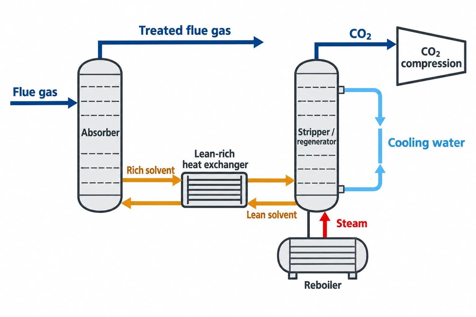
In a post-combustion capture system, treated flue gas leaves the absorber after the solvent selectively takes up CO₂. The rich solvent then passes to a stripper or regenerator. Heat supplied through the reboiler releases concentrated CO₂ and restores the solvent for return to the absorber.
This is a continuous thermal duty, not a brief start-up requirement. Reboiler steam, solvent circulation, lean-rich heat exchange, cooling water and CO₂ compression must operate together at the required capture rate. Poor heat integration increases imported steam, raises cooling demand and can displace steam from existing process users or power generation.
The stated reboiler duty is not a universal performance figure. It changes with solvent chemistry, flue-gas composition, capture rate, stripper pressure, solvent loading, exchanger performance and process configuration. It nevertheless gives energy managers a practical scale against which to assess heat-recovery options.
The wider CCUS parasitic energy penalty includes more than regeneration. Flue-gas conditioning, pumps, cooling systems, solvent reclaiming and CO₂ compression also require energy. Research on post-combustion capture consistently identifies solvent regeneration and compression as the principal contributors. A project team should not judge a heat-recovery project solely by a lower reboiler duty if it increases electrical demand or disrupts production.
Industrial heat is constrained by temperature, timing and location
Waste heat has value only when its temperature, availability and location fit a real process demand. A refinery may reject substantial heat from product cooling, fired-heater flue gas or steam condensate. A cement works may have heat in kiln exhaust, preheater gases and clinker-cooler air. Chemical sites may have reactor cooling, distillation condenser duties and hot process effluents.
Those streams are not one generic heat source. A high-temperature intermittent gas stream hundreds of metres from the capture island presents a different engineering case from a steady low-temperature liquid stream beside the solvent plant. The capture reboiler also requires heat at a useful temperature level. Low-grade heat may preheat solvent or boiler feedwater, but it may not directly replace reboiler steam.
Pinch analysis puts these constraints into a common thermal model. It separates technically recoverable heat from heat that is merely present on a site energy balance.

Pinch analysis identifies the thermodynamic minimum energy requirement of your process — then designs the heat exchanger network to achieve it.
What Pinch Analysis shows in a carbon capture retrofit
Hot and cold streams define the opportunity
A pinch study begins with a validated list of process streams. Hot streams require cooling and can release heat. Cold streams require heating and can receive it. Each stream requires a supply temperature, target temperature, heat-capacity flow rate, phase-change duty where applicable, operating period, pressure constraints and practical exchanger restrictions.
For industrial carbon capture, the model should cover the existing plant and the proposed capture system. Typical capture-side cold streams may include:
- Rich solvent before the stripper.
- Boiler feedwater or condensate returning to the steam system.
- Treated-water and wash-water duties.
- Flue-gas-conditioning streams where temperature and materials constraints permit recovery.
- Capture-plant utility users that otherwise consume medium-pressure or low-pressure steam.
Typical hot streams may include lean solvent leaving the regenerator, stripper overhead condenser duties, process condensate, cooling process streams, flue gas and product streams that currently reject heat to air or cooling water.
The established lean-rich solvent exchanger is an obvious starting point, but it should not define the study scope. Site-wide pinch analysis tests whether surplus heat from the host process can serve capture demands and whether capture-side heat can relieve pressure on existing utility systems.
Composite curves reveal the thermal target
Composite curves combine hot and cold stream data into temperature-versus-heat-flow profiles. Their closest practical approach identifies the pinch. This establishes the theoretical minimum hot-utility and cold-utility targets for the defined operating case.
The Grand Composite Curve shows heat deficits and surpluses at different temperature levels. For capture integration, this matters more than a headline quantity of recovered heat. It identifies whether the site has enough heat at a temperature suitable for regeneration, whether a heat pump could lift lower-grade heat, and whether steam extraction would create a shortfall elsewhere.
The pinch is a target, not an equipment list. Engineers must apply a realistic minimum temperature approach that reflects exchanger area, fouling, corrosion, pressure drop, controllability and the selected fluids. A tighter approach can reduce steam demand on paper while driving exchanger area and cleaning requirements beyond a sensible retrofit scope.
How waste heat-to-capture integration reduces imported steam
Prioritise direct recovery before adding heat conversion
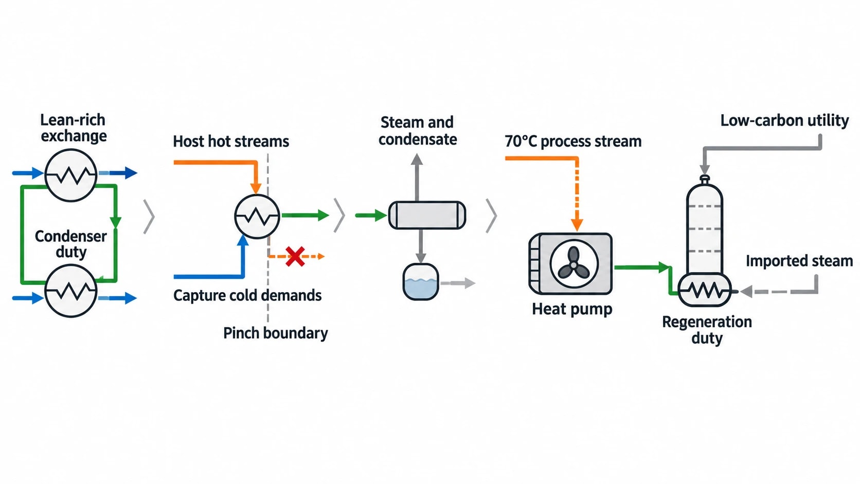
Direct process-to-process exchange usually offers the clearest route to lower thermal demand. A hot process stream may preheat rich solvent, feedwater or another capture-side cold stream. The recovered duty reduces the imported utility required to reach the final operating temperature.
The hierarchy is straightforward:
- Recover heat within the capture unit through effective lean-rich exchange and condenser-duty recovery.
- Match suitable host-process hot streams to capture-side cold demands without crossing the pinch.
- Reallocate steam and condensate where the revised utility balance supports it.
- Assess heat pumping, mechanical vapour recompression or other heat-upgrading options for residual low-grade heat.
- Size new low-carbon utility capacity only after fixing the heat-recovery target.
This sequence prevents a common retrofit error: sizing a new steam source against an unintegrated capture flow sheet, then finding recoverable heat after committing to the utility investment.
Low-temperature solvent regeneration requires careful targeting
Some solvent systems and process configurations seek to reduce regeneration temperature or improve heat recovery within the stripping section. This can widen the range of site heat sources that contribute to capture, but it does not make all low-temperature waste heat directly usable.
A 70°C process stream may be valuable for solvent preheating or water heating, but may need a heat pump to contribute to a higher-temperature regeneration duty. The heat pump’s electrical consumption and coefficient of performance must be assessed against the site’s electricity carbon intensity, power constraints and operating profile.
Pinch analysis establishes where the temperature lift is required. It also shows whether using waste heat in one location creates a larger utility demand elsewhere, avoiding an apparent saving recorded only within the capture project boundary.

Pinch analysis identifies the thermodynamic minimum energy requirement of your process — then designs the heat exchanger network to achieve it.
Designing the heat exchanger network around real constraints
Retrofitting is a network problem
A carbon capture plant introduces large new duties into an operating facility built around existing utility headers, pipe routes, exchanger trains and shutdown windows. The best thermodynamic match may be impractical because the relevant source is remote, available only during a different operating period or unsuitable for direct contact with the solvent system.
A practical heat exchanger network design should test:
- Plot space and pipe-rack capacity.
- Allowable pressure drop in flue gas, process fluids and steam systems.
- Fouling propensity of particulate-bearing gas streams.
- Corrosion risk from contaminants, solvent degradation products and water chemistry.
- Exchanger cleanability and isolation requirements.
- Capture turndown, host-plant load changes and start-up conditions.
- The effect on existing steam turbines, boilers and condensate-return systems.
Fouling and corrosion deserve particular attention in cement, refinery and waste-derived fuel applications. Flue gas with dust, sulphur oxides, nitrogen oxides or acidic constituents can require upstream treatment and indirect recovery arrangements. Heat recovery that compromises solvent quality or plant availability does not deliver a durable reduction in capture energy.
Avoid cross-pinch heat transfer
The pinch design rules remain useful during detailed retrofit work. Heat transfer across the pinch increases external utility requirements. Cold utility used above the pinch and hot utility used below it can also waste heat-recovery potential.
Real sites may depart from these rules for safety, controllability, layout or capital reasons. The design team should quantify the utility consequence of each departure and compare it with the cost, operability and downtime avoided.
This distinguishes a justified practical compromise from an unnoticed loss of thermal efficiency.
Sector applications for carbon capture for industrial heat
Cement: use the kiln system as an integrated heat source
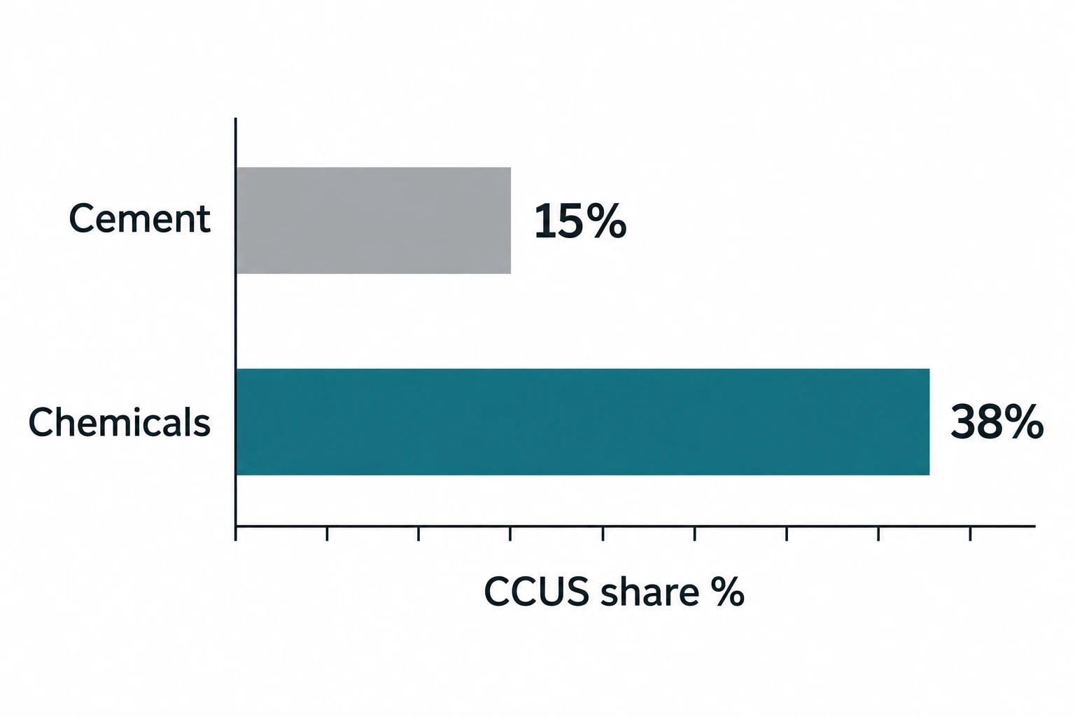
Cement capture projects face substantial process emissions from limestone calcination as well as combustion emissions. The IEA identifies CCUS as contributing 15% of the emissions reductions required in cement in its Clean Technology Scenario over 2017 to 2060.
The kiln, preheater and clinker cooler create several high-temperature and medium-temperature streams, but their availability depends on kiln operation, raw-mill mode and gas-cleaning arrangements. A pinch study can quantify whether heat from these streams can reduce capture-side heating duties without disturbing drying, raw-meal preparation or existing waste-heat recovery.
The study should model alternative operating modes rather than rely on one average heat balance. Kiln stops, mill-off periods and changes in fuel mix can alter gas temperatures and thermal loads enough to change the preferred integration scheme.
Refining: protect steam-system flexibility
Refineries often possess complex steam systems, multiple fired heaters and many large cooling duties. This creates opportunity, but also a risk that a capture plant will constrain a network designed for changing crude slates and product demand.
Pinch analysis can identify whether reboiler steam should come from an existing header, heat recovered into feedwater or condensate, or a new utility arrangement. It can also test the effect of capture operation on marginal steam generation and the cooling-water system.
The result should be an integrated steam-and-heat plan rather than a capture island that purchases steam at an assumed fixed cost.
Chemicals and ammonia: separate high-purity capture from flue-gas capture
Chemical production includes sites with relatively concentrated process CO₂ streams, alongside combustion sources where post-combustion capture may be relevant. The IEA reports that CCUS accounts for 38% of the required chemical-sector emissions reductions in its Clean Technology Scenario, a larger share than in cement or iron and steel.
Ammonia production can offer a lower-complexity capture opportunity where the process already produces a concentrated CO₂ stream. Flue-gas capture from reformer furnaces presents a different heat-integration challenge because the solvent system must treat diluted exhaust gas and regenerate solvent continuously.
A single site-wide pinch model can compare these opportunities on the same basis. It can show where process CO₂ capture releases capacity or utilities that support a later flue-gas capture phase.
Turning a Pinch Analysis target into an investment case
Build the base case from measured operating data
Historical design data rarely captures current fouling, changed production rates, modified exchangers or seasonal utility constraints. The project should use reconciled operating data across representative production cases, including stream temperatures, flow rates, steam flows, condensate returns, boiler fuel use, cooling loads and proposed capture performance guarantees.
The case should also define the capture rate, annual operating hours, CO₂ compression conditions and transport specification. Each assumption affects the capture heat balance.
The first deliverable is usually a utility target and a shortlist of feasible heat matches. The next stage converts that target into exchanger areas, pipework, tie-ins, control requirements, civil works and outage plans. Capital cost and energy savings should be assessed together, since minimum energy demand may require more exchanger area than a site can economically install.
Measure performance after commissioning
The UK Emissions Trading Scheme gives industrial operators a carbon-pricing context for verified emissions reductions, while UK CCUS policy continues to support capture, transport and storage deployment. Plant teams still need an operational energy-performance framework to verify that an integrated capture system delivers its intended benefit.
ISO 50001:2018 provides a recognised structure for managing energy performance through energy baselines, performance indicators, measurement and continual improvement. For a capture retrofit, useful indicators include reboiler heat per tonne of CO₂ captured, imported steam per tonne of CO₂ captured, electrical demand for compression, cooling duty and avoided direct emissions.
Those indicators should be interpreted with production rate, flue-gas CO₂ concentration, capture rate and ambient conditions. A lower specific reboiler duty achieved by reducing capture rate does not represent the same decarbonisation outcome.
This article reflects the independent analysis and editorial opinion of EnerTherm Engineering. Product names, trademarks, and brands mentioned belong to their respective owners. EnerTherm Engineering is not affiliated with, endorsed by, or a licensee of any third-party software or product mentioned unless explicitly stated.

Managing Director — EnerTherm Engineering
Dr. François Pierrel is Managing Director of EnerTherm Engineering with over two decades of expertise in thermal design, heat transfer, and industrial energy optimisation. He holds a PhD in Heat Transfer from Cranfield University and a Post-Doctorate from Heriot-Watt University.
