How PLC Data Cuts Distillation Column Steam by 15-25%
Integrating PLC data to separate reboiler idle load for precise energy-per-tonne KPIs.
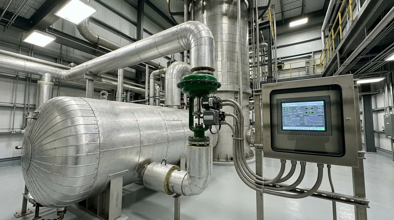
Distillation column energy monitoring is a process-level utility tracking methodology. By capturing real-time sensor data from plant programmable logic controllers (PLCs), it isolates, analyses, and optimises the thermal and electrical energy required for chemical separations.
Industrial chemical facilities rely on fractional distillation to separate liquid mixtures into high-purity components. This process requires repeated vapourisation and condensation cycles that demand massive quantities of utility steam. Indeed, distillation accounts for approximately 40 per cent of the total energy consumed in the refining and chemical bulk sectors—roughly 3 per cent of global energy consumption overall. Because of this high thermal demand, even minor operational inefficiencies in a single fractionating column can inflate a facility's annual utility expenditure by hundreds of thousands of pounds.
Historically, chemical plants managed these utility costs by assessing bills at the facility fence line or by conducting manual, retrospective spreadsheet calculations. This approach treats the entire facility as a single black box. It fails to identify which columns run sub-optimally, which reboilers are fouled, or where operators over-reflux columns to absorb upstream process disturbances. Real-time, PLC-integrated monitoring allows process engineers to transition from speculative estimates to precise, process-level utility tracking.
The Thermodynamics of Non-Linear Steam Demand
Separating Static Base-Load from Dynamic Load
To optimise a distillation column, process engineers must address the non-linear relationship between thermal energy consumption and production throughput. When a plant operates at reduced capacity, column steam consumption does not drop proportionally. This non-linear behaviour presents a significant challenge when establishing accurate energy-per-tonne Key Performance Indicators (KPIs).
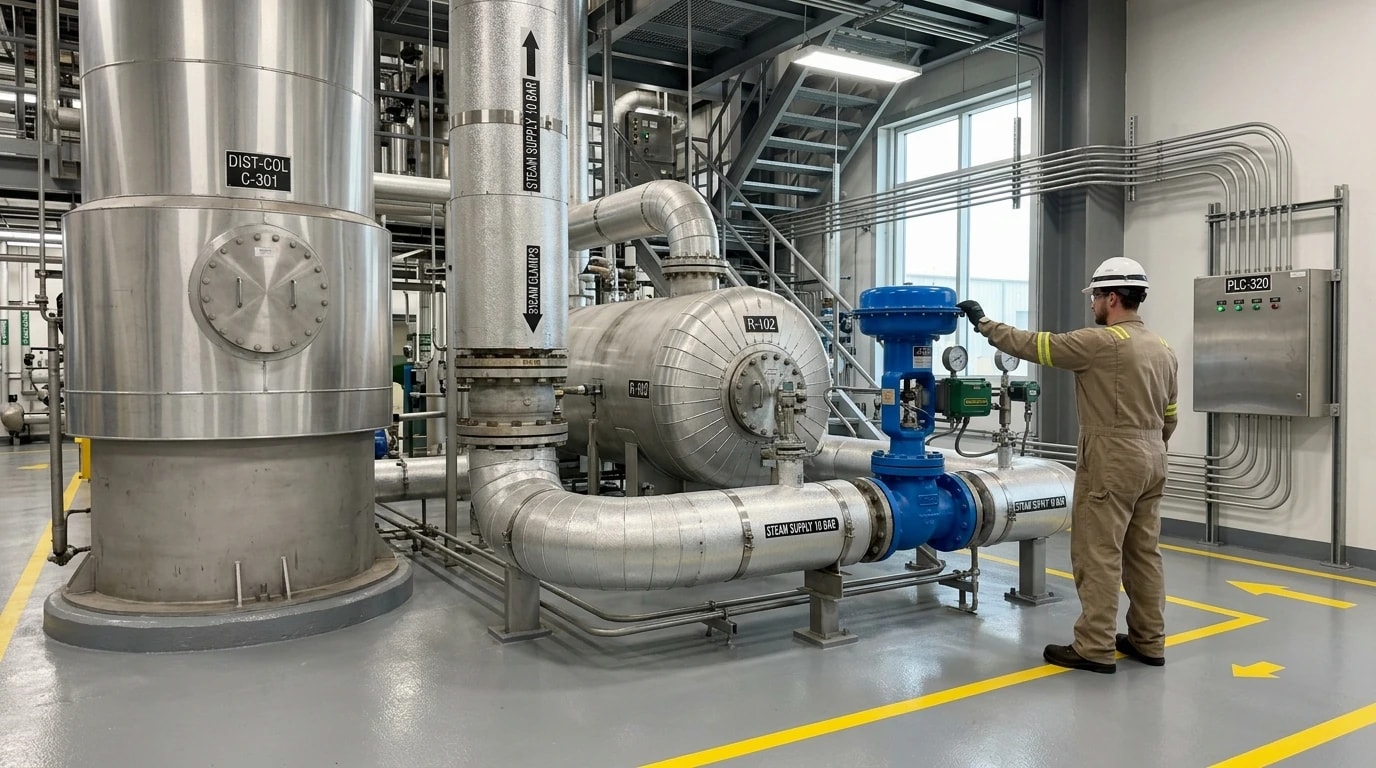
A distillation column requires a continuous minimum thermal input to maintain vapour-liquid equilibrium, regardless of feed rate. This is known as the static base-load thermal consumption, or reboiler idle load. Thus, total steam feed to the reboiler consists of two portions: the static base-load and the dynamic, production-linked utility draw.
Static base-load steam heats the column structure, compensates for ambient heat losses, and maintains the minimum vapour velocity needed to hold liquid on the distillation trays. Only the steam consumed above this baseline directly drives separation. When production rates decline, specific energy consumption (steam consumed per tonne of product) increases because the static base-load remains constant. Continuous PLC data integration allows analytics platforms to isolate this fixed base-load from the dynamic, throughput-driven draw, delivering a clear mathematical picture of true column efficiency across varying production rates.
The Risk of Tray Weeping and Minimum Vapour Velocity
In trayed columns, the upward velocity of the vapour must prevent liquid from draining through the tray perforations. If vapour velocity falls below a critical threshold, weeping occurs. Liquid then bypasses the active separation zones, falling directly to the column sump. This severely degrades separation efficiency, rendering the column unable to meet product specifications.
To prevent weeping during low-throughput periods, operators frequently maintain high steam rates to the reboiler to sustain vapour velocity. While this keeps the column hydraulically stable, it carries a massive energy penalty. Real-time monitoring of tray differential pressure and reboiler steam flow allows process engineers to identify exactly where vapour velocity approaches the weeping limit. These data insights enable operators to implement advanced pressure-reduction strategies, safely maintaining hydraulic stability at lower thermal inputs.
Omni Vision delivers turnkey utility metering, CO2 tracking, and AI-powered production KPI intelligence — giving you real-time dashboards and actionable insights across your entire facility.
Physical Parameters Required for Real-Time Calculation Loops
Reboiler Steam Flow Rate and Heat Duty Calculations
The primary thermal input to a distillation column is the heat supplied to the reboiler. To calculate this thermal duty (Q), the monitoring system requires continuous data from steam flow transmitters, pressure sensors, and condensate temperature transmitters. The heat transfer rate within the reboiler depends on the mass flow rate of the steam (m˙steam) and the latent heat of condensation (Δhvap,steam) at the operating supply pressure:
Q=m˙steam⋅Δhvap,steamWhere:
- Q is the reboiler heat load in kilowatts (kW)
- m˙steam is the mass flow rate of steam in kilograms per second (kg/s)
- Δhvap,steam is the latent heat of condensation of steam at the supply pressure in kilojoules per kilogram (kJ/kg)
If the steam supply is superheated, or if the condensate is sub-cooled before leaving the reboiler, the calculation loop must incorporate sensible heat changes to maintain accuracy. Real-time tracking of these variables allows the system to identify heat exchanger fouling, steam trap failures, and utility supply fluctuations that degrade reboiler performance.
Reflux Flow Rates and the Penalty of Specification Overshoot
Reflux is the portion of condensed overhead vapour returned to the top of the column to enrich the vapour phase with the more volatile component. The reflux ratio—the ratio of reflux flow to distillate product flow—is the primary control variable used to manage product purity.
Operating teams often run columns with an excessively high reflux ratio. This practice, known as specification overshoot, buffers the column against upstream process upsets to ensure that the final product remains safely within purity limits. For example, if a column requires a 95 per cent purity target, operators might run it at 99 per cent purity to avoid off-specification incidents. This 4 per cent purity overshoot can increase reboiler energy consumption by more than 30 per cent. Continuous monitoring of the reflux flow rate via PLC data highlights this energy-purity trade-off, enabling operators to tighten control margins and reduce excess steam consumption without risking product quality.
Differential Pressure and Internal Vapour Velocity Dynamics
Column differential pressure is the difference in pressure between the bottom sump and the overhead vapour line, serving as a direct indicator of vapour velocity and hydraulic resistance.
When vapour velocity increases, differential pressure rises. Real-time monitoring of this delta allows the system to detect the early stages of column flooding, where liquid accumulates in the upper sections due to excessive vapour flow. Conversely, a drop in differential pressure below calculated limits warns of potential tray weeping. Integrating this metric into the energy analytics engine ensures that steam reduction recommendations do not compromise column hydraulics.
Multi-Stage Tray Temperature Profiles for Composition Control
Monitoring temperatures at key locations provides a surrogate measure of the internal composition profile. In a typical binary column, temperature sensors are located in the stripping section, near the feed tray, and in the rectifying section.
Because boiling points relate directly to composition at a given operating pressure, these profiles allow the system to infer target component concentrations on each tray. When combined with real-time pressure data to compensate for pressure-induced boiling point shifts, multi-stage temperature profiles allow the analytics engine to detect composition drift instantly. This provides the critical recommendations needed for operators or building-management systems to adjust reboiler steam rates dynamically during validated change windows, ensuring the column uses only the minimum thermal energy required for separation.
| Physical Parameter | Sensor Type | Primary Use in Energy Analytics |
|---|---|---|
| Reboiler Steam Flow | Orifice plate, Vortex, or Coriolis | Calculates total thermal energy input |
| Reflux Flow Rate | Electromagnetic or Vortex | Monitors reflux ratio and detects specification overshoot |
| Differential Pressure | Differential pressure transmitter | Indicates internal vapour velocity and hydraulic stability |
| Multi-Stage Tray Temp | Resistance Temperature Detectors (RTDs) | Infers composition profiles and prevents over-purification |
Technical Architecture for Secure PLC Data Integration
Industrial Communication Protocols on the Plant Floor
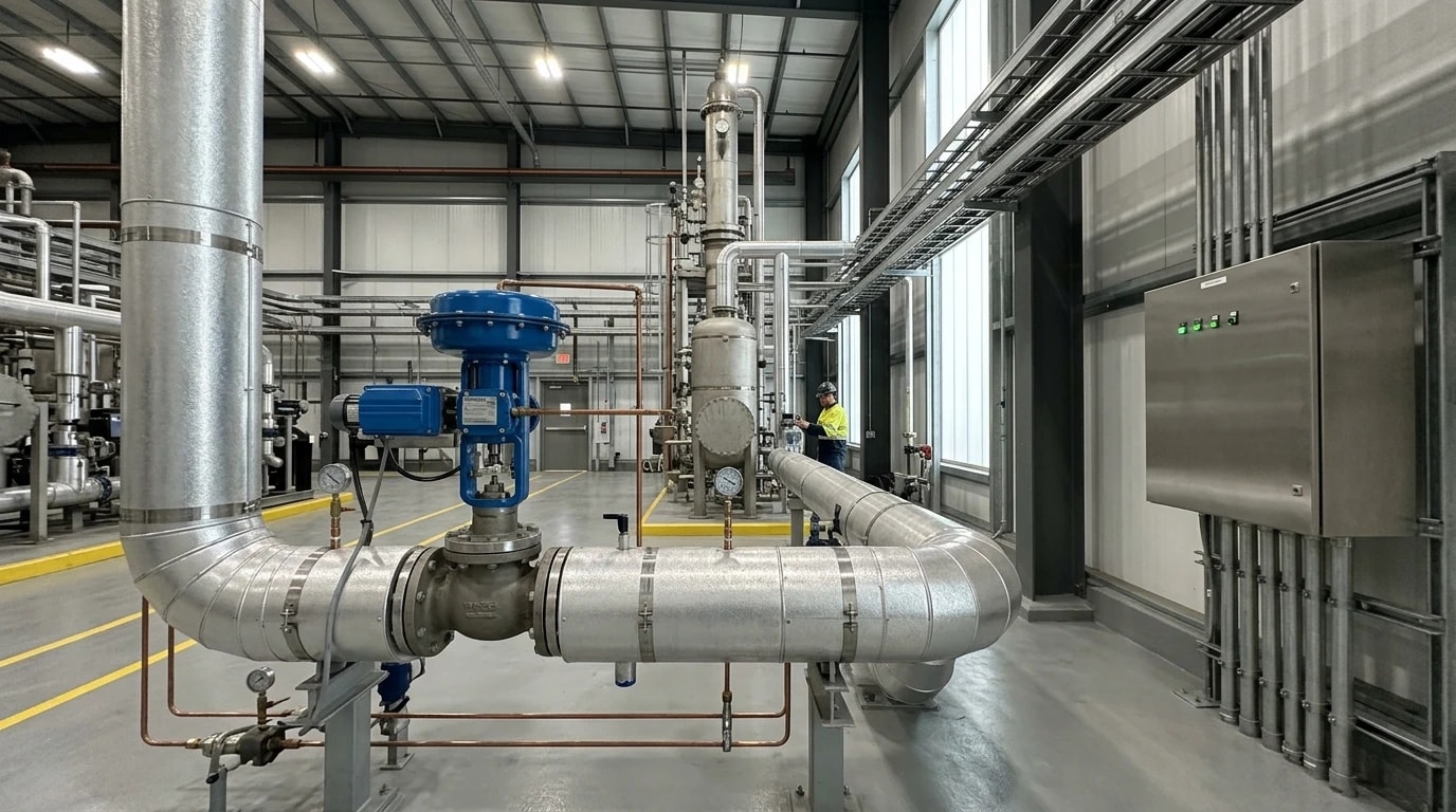
To establish effective monitoring, data must flow securely from physical sensors to the analytical environment. Industrial control systems rely on various communication protocols to manage process loops. A modern energy monitoring implementation must interface with these existing systems without requiring a complete instrument overhaul.
Process engineers typically configure edge gateways to communicate via Modbus TCP, OPC-UA, or MQTT. Modbus TCP offers a straightforward method for polling register data from legacy PLCs and local flow transmitters. OPC-UA provides a structured, object-oriented data model including metadata, ensuring sensor readings retain their engineering units and context. MQTT, with its lightweight publish-subscribe architecture, is highly suited for transmitting high-frequency process variables to cloud servers over restricted bandwidth.
One-Way Encrypted Data Transfer and OT Security
Securing operational technology (OT) networks is critical in chemical manufacturing. External software platforms must never write commands back to the plant control system, as unauthorised write access could compromise safety interlocks or trigger process upsets.
Consequently, the data extraction architecture employs physical or software-defined data diodes to enforce a strict, one-way outbound data flow. The edge gateway collects data from plant PLCs and transmits it via encrypted Transport Layer Security (TLS) to the cloud analytics platform. Because the gateway has zero-write privileges on the PLC network, the integrity of safety instrumented systems and regulatory control loops remains protected. This unidirectional architecture ensures compliance with international industrial cybersecurity standards, such as IEC 62443.
Integrating the Omni Vision Platform and Cloud Analytics
Under the Omni Vision Energy Intelligence Platform, EnerTherm Engineering integrates these secure hardware connectivity methods with cloud-based analytics [Parent Category Context, Business Context (EnerTherm)]. The platform serves as the central data ingestion layer, pulling high-frequency readings for electricity, gas, water, steam, compressed air, and oil [Parent Category Context, Business Context (EnerTherm)]. A secure, non-invasive gateway relays this multi-utility data directly to the cloud-based AI analytics engine developed by EPSA [Parent Category Context, Business Context (EnerTherm)]. This separation of concerns keeps physical instrumentation and PLC connectivity isolated on-site, while cloud-based models perform the computationally intensive calculations required to isolate the column's thermal efficiencies [Parent Category Context].
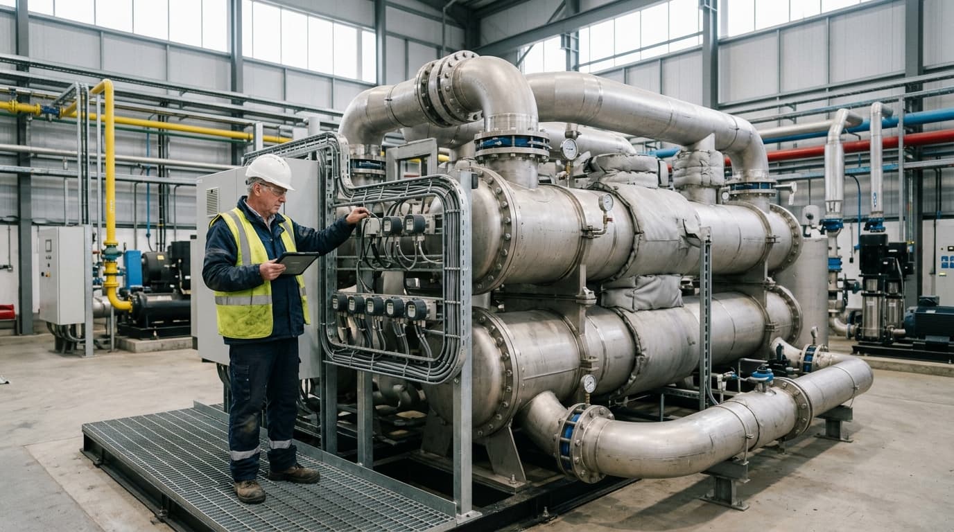
Track energy consumption, emissions, and process parameters with seamless PLC/SCADA integration via Modbus, OPC-UA, and MQTT protocols.
Managing Signal Noise and Instrument Calibration Drift
Signal Filtering and Data Validation Algorithms
Raw data extracted from plant PLCs often contains significant high-frequency noise. Flow transmitters, particularly orifice plates and vortex shedding meters, experience rapid signal fluctuations caused by turbulent flow regimes or control valve adjustments. If these raw, unfiltered measurements are passed directly into thermodynamic calculation loops, the resulting energy metrics will oscillate too rapidly to assist operational decision-making.
To resolve this, the cloud-based analytics engine applies digital processing techniques. Moving average, low-pass Butterworth, or Savitzky-Golay smoothing algorithms execute within the cloud layer to remove high-frequency noise. These algorithms preserve true thermodynamic transitions while filtering out transient process spikes, ensuring that the displayed Specific Steam Consumption KPI represents real column behaviour rather than instrument noise.
Detecting Instrument Calibration Drift and Anomaly Mitigation
Physical sensors in chemical processing environments are prone to calibration drift over extended operating cycles. A temperature transmitter on a distillation tray that drifts by even 0.5 °C can lead to incorrect composition estimates, misleading operators into supplying unnecessary steam to the reboiler and silently eroding energy efficiency.
To address sensor degradation, the analytics engine compares real-time measurements against expected thermodynamic baselines. By evaluating multi-stage temperature profiles alongside column pressure and reboiler steam flow rates, the system detects anomalies indicating instrument drift [Parent Category Context, Business Context (EnerTherm)]. If a temperature sensor deviates from the physical envelope predicted by the column model, the platform flags the instrument for maintenance. This proactive detection ensures the long-term accuracy of calculation loops, preventing unnoticed drift from inflating utility bills.
Process-Linked KPIs and Regulatory Compliance Reporting
Establishing the Real-Time Specific Steam Consumption KPI
Transforming raw physical data into actionable business insights requires process engineers to map utility consumption directly against production output [Parent Category Context, Business Context (EnerTherm)]. Assessing total steam consumption in isolation is ineffective, as a reduction in steam usage may simply reflect a plant shutdown or a lower feed rate.
To establish a reliable benchmark, the analytics platform calculates Specific Steam Consumption (SSC) in real time:
SSC=m˙productm˙steamWhere:
- SSC is the Specific Steam Consumption in tonnes of steam per tonne of product.
- m˙steam is the mass flow rate of steam to the reboiler in tonnes per hour.
- m˙product is the mass flow rate of on-specification distillate or bottoms product in tonnes per hour.
By calculating this KPI continuously, the platform maps the non-linear curve of the column's energy intensity [Parent Category Context]. This allows operations directors to compare the energy cost per tonne across different shifts, feed compositions, and ambient conditions—turning raw data into direct financial insights [Parent Category Context, Business Context (EnerTherm)].
Standardised Carbon Accounting for UK and European Regulations
Industrial sites in the United Kingdom and Europe are subject to strict regulatory frameworks governing greenhouse gas emissions and energy efficiency [Parent Category Context]. Continuous distillation column monitoring provides the high-resolution, verifiable data required to satisfy these compliance standards [Parent Category Context, Business Context (EnerTherm)].
Automated utility data collection simplifies compliance with the UK Energy Savings Opportunity Scheme (ESOS) and the Streamlined Energy and Carbon Reporting (SECR) framework [Parent Category Context]. By tracking exact steam and electricity draw at the process level, the platform calculates Scope 1 emissions (from on-site fuel combustion for steam generation) and Scope 2 emissions (from imported electricity used for pumps and reflux condensers) with audit-grade accuracy [Parent Category Context, Business Context (EnerTherm)]. Additionally, this continuous monitoring aligns with ISO 50001:2018 energy management systems by providing the objective, real-time energy baselines required to demonstrate continuous improvement [Parent Category Context]. For facilities operating under the EU ETS or the UK Emissions Trading Scheme, this high-resolution data ensures accurate carbon emissions reporting, reducing the risk of compliance penalties [Parent Category Context].
Practical Strategies for Achieving 15 to 25 per cent Steam Reductions
Dynamic Reflux Optimisation and Pressure Reduction
Once a chemical plant establishes real-time monitoring, process engineers can implement targeted optimisation strategies to reduce thermal demand [Keyword]. One of the most effective methods is dynamic reflux optimisation.
Operating teams historically run distillation columns with an excessively high reflux ratio to buffer against feed fluctuations. By using real-time composition recommendations derived from tray temperature and pressure sensors, operators can safely lower the reflux ratio closer to the thermodynamic minimum. Additionally, reducing column operating pressure during cooler ambient conditions increases the relative volatility of the chemical components. This reduces the energy required for the same separation, allowing a significant reduction in reboiler steam flow without compromising product purity.
Detecting Heat Exchanger Fouling and Steam Trap Failures
Thermal efficiency in a distillation system degrades over time due to mechanical wear and fouling. Reboilers frequently experience scale build-up on the process side or organic fouling on the utility side, reducing the heat transfer coefficient.
By continuously monitoring the reboiler steam flow rate alongside process temperatures, the analytics engine calculates the real-time heat transfer coefficient (U). A downward trend in this value flags early-stage fouling, allowing maintenance teams to schedule cleaning before the efficiency drop becomes severe. Similarly, the system monitors condensate temperatures to detect failing steam traps. A blowing steam trap allows live steam to escape into the condensate return line, inflating thermal costs, while a blocked trap causes condensate to back up into the reboiler, reducing the active heat transfer area and destabilising the column.
The Structured Deployment Path and Financial Returns
Transitioning from manual spreadsheet tracking to automated utility intelligence follows a structured deployment path [Business Context (EnerTherm)]. The Omni Vision Energy Intelligence Platform employs an 8-to-16-week deployment timeline that operates entirely in parallel with active production [Parent Category Context, Business Context (EnerTherm)].
During the initial weeks, engineers map the existing plant PLCs and identify the necessary Modbus or OPC-UA data registers [Parent Category Context, Business Context (EnerTherm)]. The edge gateway is then installed in the facility's control panel without requiring a process shutdown [Parent Category Context]. In the subsequent weeks, the secure data pipeline to EPSA's cloud-based AI analytics engine is established, allowing the machine learning models to baseline the column's static and dynamic loads [Parent Category Context, Business Context (EnerTherm)]. The final phase deploys process-level dashboards that display real-time Specific Steam Consumption KPIs [Parent Category Context, Business Context (EnerTherm)].
By combining dynamic reflux optimisation, pressure reduction, and proactive heat exchanger maintenance, chemical processors consistently achieve a 15 to 25 per cent reduction in distillation column steam consumption [Parent Category Context, Business Context (EnerTherm)]. Since steam represents a major operating expense, these thermal savings deliver a sub-12-month ROI—making the transition to automated energy intelligence a highly effective strategy for modern chemical manufacturers [Parent Category Context, Business Context (EnerTherm)].
This article reflects the independent analysis and editorial opinion of EnerTherm Engineering. Product names, trademarks, and brands mentioned belong to their respective owners. EnerTherm Engineering is not affiliated with, endorsed by, or a licensee of any third-party software or product mentioned unless explicitly stated.

Technical Manager — EnerTherm Engineering
John Naranjo is Technical Manager at EnerTherm Engineering, bringing specialist expertise in chemical and environmental engineering. He recently led the implementation of Omni Vision, EnerTherm's real-time energy and utility monitoring platform. He holds an MSc in Environmental Engineering from the University of Huelva and a BSc in Chemical Engineering, with memberships in both the Energy Institute and IChemE.
