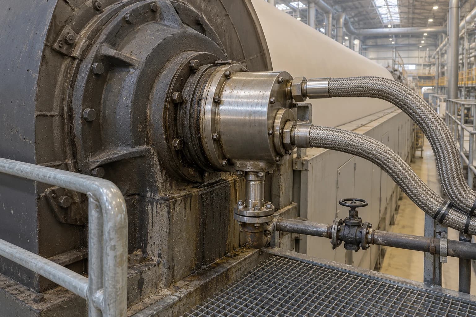
Paper Mill Dryer Drainage Retains Up to 16% of Steam Energy
A dryer-section diagnosis targeting 90% condensate return to the boiler.
Paper mill dryer drainage is the controlled removal of condensate and blow-through steam from steam-heated dryer cylinders to maintain heat transfer into the paper web. Focus on Energy reports that condensate can retain up to 16% of the energy used to produce steam, making drainage and recovery a central issue in steam system optimisation for paper mills.
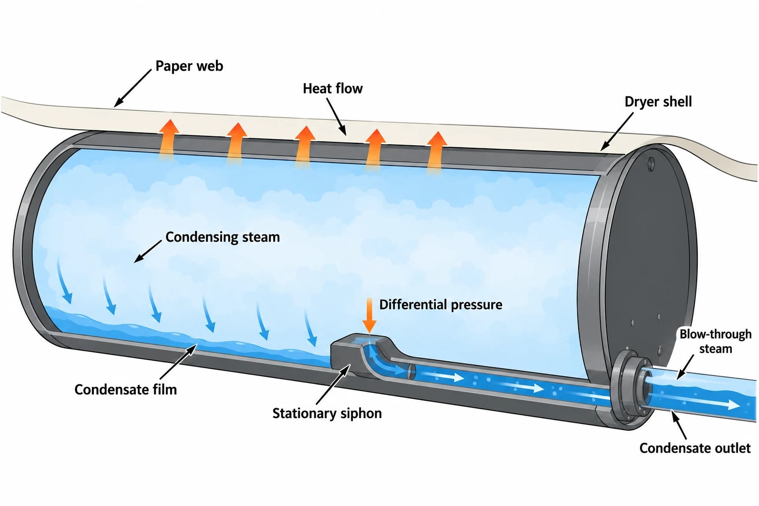
Steam enters a dryer cylinder, condenses against the inner shell and transfers latent heat through the metal to evaporate water from the sheet. The condensate then needs a reliable route out of the rotating cylinder.
A drainage fault can leave a condensate layer inside the cylinder, reduce heat transfer, disturb pressure control and drive operators towards higher steam pressures. Excess blow-through steam creates the opposite problem. It moves valuable vapour through the drainage system without delivering useful drying duty, adding load to separators, condensers and low-pressure steam equipment.
For tissue, packaging and corrugated-board facilities, the practical target is stable drying at the required moisture profile, with the highest possible recovery of clean hot condensate. Focus on Energy identifies 90% condensate return to the boiler as a target for paper mills. The route to that figure depends on condensate quality, pressure levels, available heat users and the condition of the drainage system.
Why dryer drainage matters in paper mill steam system optimisation
Paper drying can account for up to 80% of a paper machine's steam consumption. That makes the dryer section a high-value part of an industrial energy audit, especially where fuel costs, steam capacity or carbon exposure constrain production.
Heat transfer depends on removing condensate
Condensing steam transfers heat efficiently when it contacts the internal dryer shell. If condensate accumulates, it creates a liquid layer between the steam and shell. Water transfers heat far less effectively in this arrangement than steam condensing directly on the metal surface.
The production effect often appears before the energy effect. Operators may see unstable dryer pressures, uneven moisture, restricted speed, changing steam demand or increasing manual intervention. On tissue machines, altered drying conditions can affect creping and sheet properties. On packaging and board machines, moisture variation can reach the converting line as curl, stiffness variation or poor dimensional performance.
Increasing steam pressure may raise cylinder surface temperature, but it does not correct poor drainage. The system needs sufficient differential pressure, an effective siphon arrangement and stable separation of condensate from vapour.
Blow-through steam has a direct energy cost
A controlled amount of blow-through steam may be needed to move condensate through the siphon and drainage circuit. The required quantity changes with machine speed, dryer diameter, condensate load and siphon design.
Excess blow-through uses boiler steam without delivering its intended latent heat to the paper web. It can disrupt separator level control, overload condenser capacity and increase vent losses. The audit question is specific: does each dryer group have enough differential pressure to evacuate condensate without continuously passing more steam than its drainage system requires?
Stationary siphons can operate with lower differential pressure in suitable applications, reducing blow-through and the risk of dryer flooding. Scoop siphons remain relevant on slower-running machines where centrifugal effects support condensate removal. Siphon selection should follow the machine's operating range, dryer dimensions and grade mix rather than a site-wide rule.
Condensate is a process stream, not a waste stream
Hot condensate holds useful sensible heat. Its value depends on temperature, pressure, cleanliness and demand elsewhere in the mill.
Direct return to the boiler house can reduce boiler feedwater heating demand, make-up water use and water-treatment load. Where direct return is unsuitable, condensate may still supply process-water, shower-water or building-heating duty. The aim is to retain the stream at the highest useful temperature before it reaches a lower-grade use or drain.
A mill should avoid sending high-temperature condensate to a vacuum condenser simply because the drainage arrangement makes that convenient. The system design should first examine whether the condensate can return at pressure, flash to a useful lower-pressure steam demand or heat a suitable water circuit.
Identify where your plant is losing energy and quantify the savings potential — our audits map every heat source, sink, and waste stream in your facility.
Where paper machine dryer drainage loses energy
Dryer drainage losses tend to develop through several small problems rather than one obvious failure. A steam system survey should trace flow from each dryer group through separators, flash vessels, condensate receivers, pumps and heat users.
False differential-pressure measurements
Differential pressure is the principal operating variable for dryer drainage. A misleading signal can make a sound mechanical system look faulty, or hide a genuine restriction while the control loop compensates in the wrong direction.
Common causes include blocked impulse lines, unequal water legs, poor transmitter location, incorrect compensation, condensate-filled tubing and instruments that have drifted from calibration. Pressure and differential-pressure readings should be checked during stable production and during grade changes, sheet breaks and speed changes.
Smart transmitters can improve diagnosis where the underlying installation is sound, but they do not correct poor impulse-line practice. An audit should first verify that the pressure difference shown in the control room represents the pressure difference across the dryer drainage circuit.
Worn siphons and rotary joints
A siphon has to remove condensate from a rotating cylinder under changing speed and load conditions. Wear, internal blockage, incorrect clearance, poor alignment or damage can reduce its capacity. Rotary-joint faults can introduce steam leakage, air ingress or condensate-flow restriction.
These issues can remain hidden during lower-load production and emerge only on demanding grades. A maintenance programme should connect inspections to operating data. Repeated pressure instability or high blow-through in one dryer group may justify closer examination of that group's siphon, joint and internal hardware.
Dryer bars can influence performance by disrupting the condensate layer inside the cylinder. Their suitability depends on the dryer arrangement and operating conditions, so they require a process review rather than a blanket retrofit decision.
Separator and flash-vessel instability
Separators must separate condensate and flash steam at the intended pressure. A vessel operating beyond its effective capacity can carry liquid into vapour lines or vapour into condensate lines. Both outcomes destabilise downstream control.
Level behaviour matters. Poorly controlled flash tanks and condensate receivers can cause pump problems, uncontrolled venting and pressure fluctuation. The audit should establish normal level ranges, actual level-control response, vent destination and the available capacity of the receiving system.
Leakage, venting and insulation losses
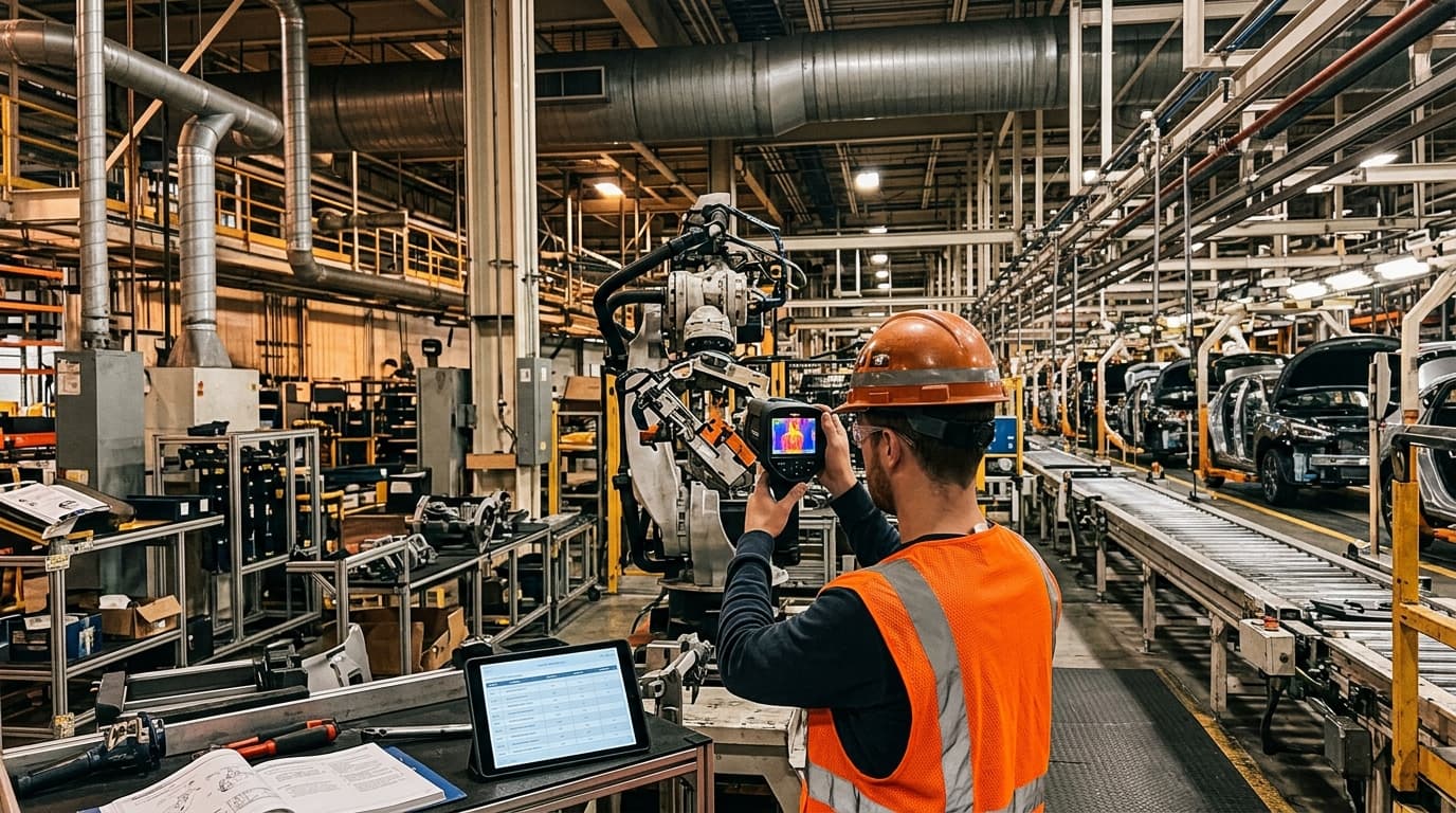
Leaking isolation valves, control valves and vents can bypass steam continuously. Thermal imaging and ultrasonic testing can identify many of these losses, particularly around drainage stations, valve banks and inaccessible pipe bridges.
ANSI/FCI 70-2 Class IV is a control-valve seat-leakage classification. It can be specified for applicable vent or isolation control valves where shut-off performance is required. It should not be used as a specification for safety-relief valves.
Safety-relief valves need selection, sizing, set pressure, certification and installation appropriate to the protected pressure system and its pressure-relief requirements. A drainage survey should record each vent's operating purpose before changes are made. A vent may be masking a separator, control-loop or condenser problem elsewhere in the system.
Uninsulated valves, fittings, flash vessels and condensate lines also lose heat continuously. A thermal survey should cover components behind guards and in congested dryer basements, not only accessible straight pipe runs.
How to audit a paper mill dryer condensate system
A useful audit separates visible defects from operating problems that appear only during production changes. A walk-round can find leaks and damaged insulation, but cannot show whether drainage control remains stable across basis weights, grades and machine speeds.
Build a live steam and condensate balance
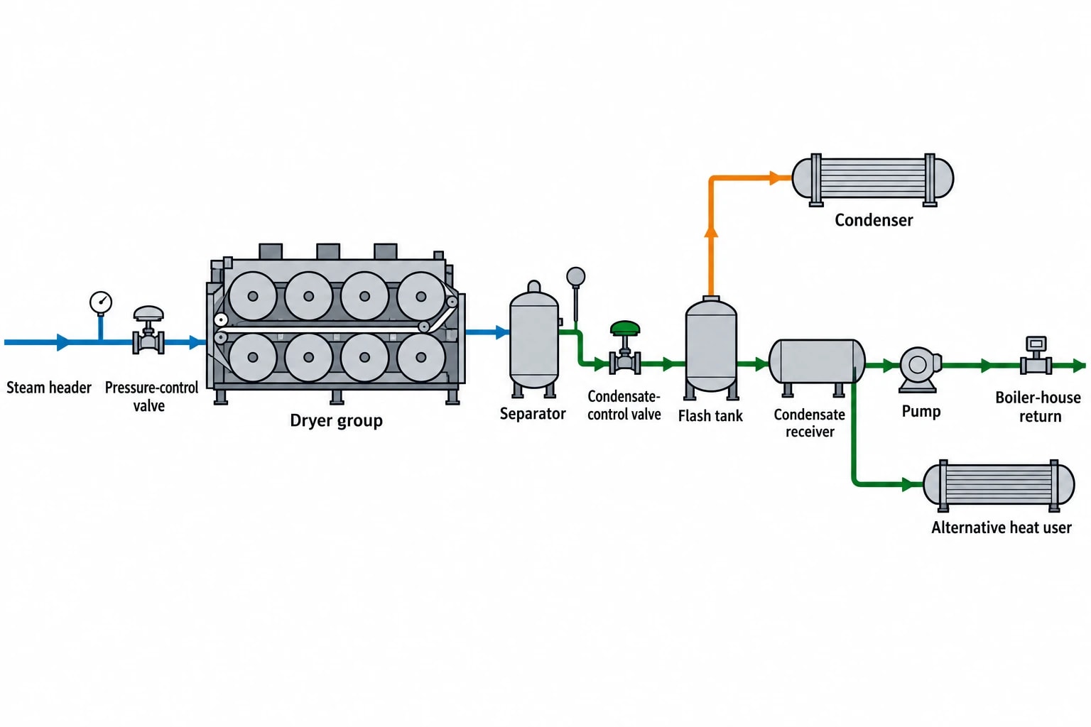
The starting point is a process flow sheet showing:
- Steam headers and dryer groups
- Dryer pressure-control valves
- Separators and condensate-control valves
- Flash tanks, vents and condensers
- Condensate receivers and pumps
- Boiler-house returns and alternative heat users
- Known drains, bypasses and relief paths
Each connection needs a normal pressure level, flow direction and operating role. Measured data should replace assumptions where practical. Time-stamped pressure, temperature and flow trends can then be compared with machine speed, basis weight, sheet moisture and grade changes.
The table below identifies the measurements that most often clarify a drainage problem.
| Measurement | What it shows | Audit use |
|---|---|---|
| Dryer-group pressure | Saturation condition and temperature potential | Identifies unstable steam supply or inappropriate pressure targets |
| Differential pressure | Driving force for condensate removal | Shows whether drainage control has enough margin |
| Blow-through flow | Steam carried through the drainage system | Reveals excessive vapour use and opportunities for control improvement |
| Separator pressure and level | Vapour-liquid separation performance | Identifies carryover, flooding or unstable control |
| Condensate temperature and conductivity | Heat value and return quality | Helps select boiler return or secondary heat-recovery routes |
| Boiler make-up-water use | Return-system performance | Highlights lost condensate and possible leakage |
| Fuel use per tonne | Overall energy outcome | Supports normalised performance assessment |
Test the system during meaningful operating conditions
Dryer drainage should be assessed across the production range, not only at a convenient steady state. Grade changes, sheet breaks and changes in machine speed can expose poor control tuning or insufficient drainage capacity.
Auditors should look for:
- Pressure swings that coincide with speed or grade changes.
- High blow-through after a sheet break.
- Separator-level hunting or recurring high-level alarms.
- Condensate temperature falling unexpectedly before the boiler house.
- Excessive venting from flash vessels or condensate receivers.
- Different performance between dryer groups at similar duties.
- Rising boiler make-up water without an explained production cause.
Portable pressure instruments, thermal imaging and ultrasonic leak detection provide valuable field evidence. They should support, rather than replace, the machine historian and operator knowledge. A control-room trend may establish when a disturbance occurred; an inspection can establish why.
Check condensate quality before increasing recovery
Clean condensate has high value. Contaminated condensate can create boiler chemistry problems that outweigh the apparent energy saving.
Conductivity monitoring, sample analysis and segregated drainage routes help protect the boiler system. Mills should identify which condensate streams are suitable for direct return, which require treatment or monitoring, and which are better suited to indirect heat recovery.
The same review applies to proposed heat-recovery duties. Shower-water heating, process-water heating and feedwater preheating have different temperature, cleanliness and reliability requirements. A heat exchanger can recover energy safely where direct mixing or direct boiler return is unsuitable.

Identify where your plant is losing energy and quantify the savings potential — our audits map every heat source, sink, and waste stream in your facility.
Matching secondary condensate to useful heat demand
Commission Implementing Decision 2014/687/EU identifies the appropriate use of secondary heat and secondary condensate as an energy-efficiency measure for pulp, paper and board mills. The associated BAT Reference Document also highlights integrated heat-exchanger networks and recovery of low-temperature streams for boiler feedwater, process water and buildings.
Use heat at the highest practical temperature
The JRC BAT Reference Document describes staged clean-hot-water systems at 80 to 90°C, 60 to 70°C and 40 to 50°C. These levels provide a useful structure for evaluating recovery opportunities.
High-temperature condensate should not automatically serve a low-temperature load if a higher-temperature duty remains unmet. Equally, a lower-temperature demand should not force a complex recovery scheme if a simpler clean-water loop can meet the requirement.
A staged approach can include:
- High-temperature condensate or flash steam for boiler feedwater heating where quality and pressure permit.
- Medium-temperature secondary condensate for process-water or shower-water heating.
- Lower-temperature recovered heat for building heating or other low-grade site loads.
The selected route must preserve stable dryer drainage. Recovery equipment that raises back-pressure, restricts condensate flow or creates control interaction can damage production performance. A heat-recovery proposal needs hydraulic and control review as well as an energy calculation.
Focus on the whole water and steam balance
Dryer condensate recovery affects more than boiler firing. It can reduce make-up water demand, chemical use and wastewater load. It can also alter the temperature of water circuits used elsewhere in the mill.
That interaction requires coordination between paper-machine operations, boiler-house staff, maintenance teams and water-treatment specialists. An isolated upgrade may save energy locally while shifting instability to a condenser, receiver or boiler-feed system.
Prioritising drainage improvements without disrupting production
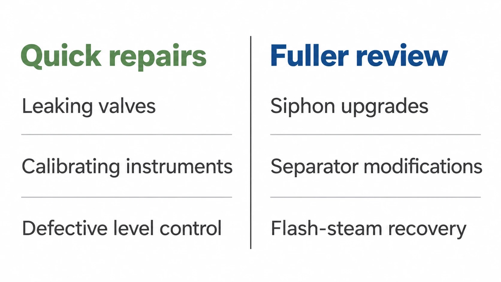
The best improvement plan ranks measures by operating risk, evidence and outage requirement. It should distinguish quick repairs from projects that need process design, supplier input or planned shutdown work.
Low-disruption measures
Typical near-term actions include repairing leaking valves and joints, reinstating insulation, correcting transmitter installation, clearing impulse lines, calibrating instruments and addressing defective level control.
These measures often improve visibility and reliability before capital spending begins. They also provide the data needed to justify larger changes.
Projects requiring fuller process design
Siphon upgrades, separator modifications, flash-steam recovery, condensate-pump changes and condenser-capacity projects require a fuller review. Engineers should assess pressure balance, control philosophy, contamination risk, shutdown needs and the response to sheet breaks.
The business case should include fuel, water, treatment chemicals, maintenance, production risk and expected emissions impact. It should state whether savings depend on specific grades, operating hours or ambient conditions.
For UK ETS-regulated installations, verified fuel-metering records may also support carbon reporting where required. Those records should remain separate from an engineering savings claim unless the project baseline, boundary and production adjustments have been defined.
Maintaining dryer drainage performance after the audit
Drainage performance changes as equipment wears, grade mixes evolve and control systems are modified. A completed project needs routine checks to retain its value.
Use operating envelopes, not one fixed target
A single steam-pressure target rarely suits every dryer group or product grade. Control-room trends should compare current conditions against an agreed operating envelope for the active grade, including dryer-group pressure, differential pressure, separator level, condensate temperature and vent behaviour.
A sudden change in one indicator should trigger inspection before operators raise steam pressure to compensate. That response often hides the root cause while increasing fuel demand.
Verify savings against comparable production
Fuel use per tonne can change for reasons unrelated to drainage. Production rate, basis weight, inlet moisture, finished moisture, grade mix and downtime all affect the result.
A measurement and verification plan should define the baseline period, reporting period, included fuel and water streams, meter checks, production variables and exclusions. The result should show whether dryer drainage has improved heat transfer and condensate recovery under comparable operating conditions.
This article reflects the independent analysis and editorial opinion of EnerTherm Engineering. Product names, trademarks, and brands mentioned belong to their respective owners. EnerTherm Engineering is not affiliated with, endorsed by, or a licensee of any third-party software or product mentioned unless explicitly stated.

Managing Director — EnerTherm Engineering
Dr. François Pierrel is Managing Director of EnerTherm Engineering with over two decades of expertise in thermal design, heat transfer, and industrial energy optimisation. He holds a PhD in Heat Transfer from Cranfield University and a Post-Doctorate from Heriot-Watt University.
