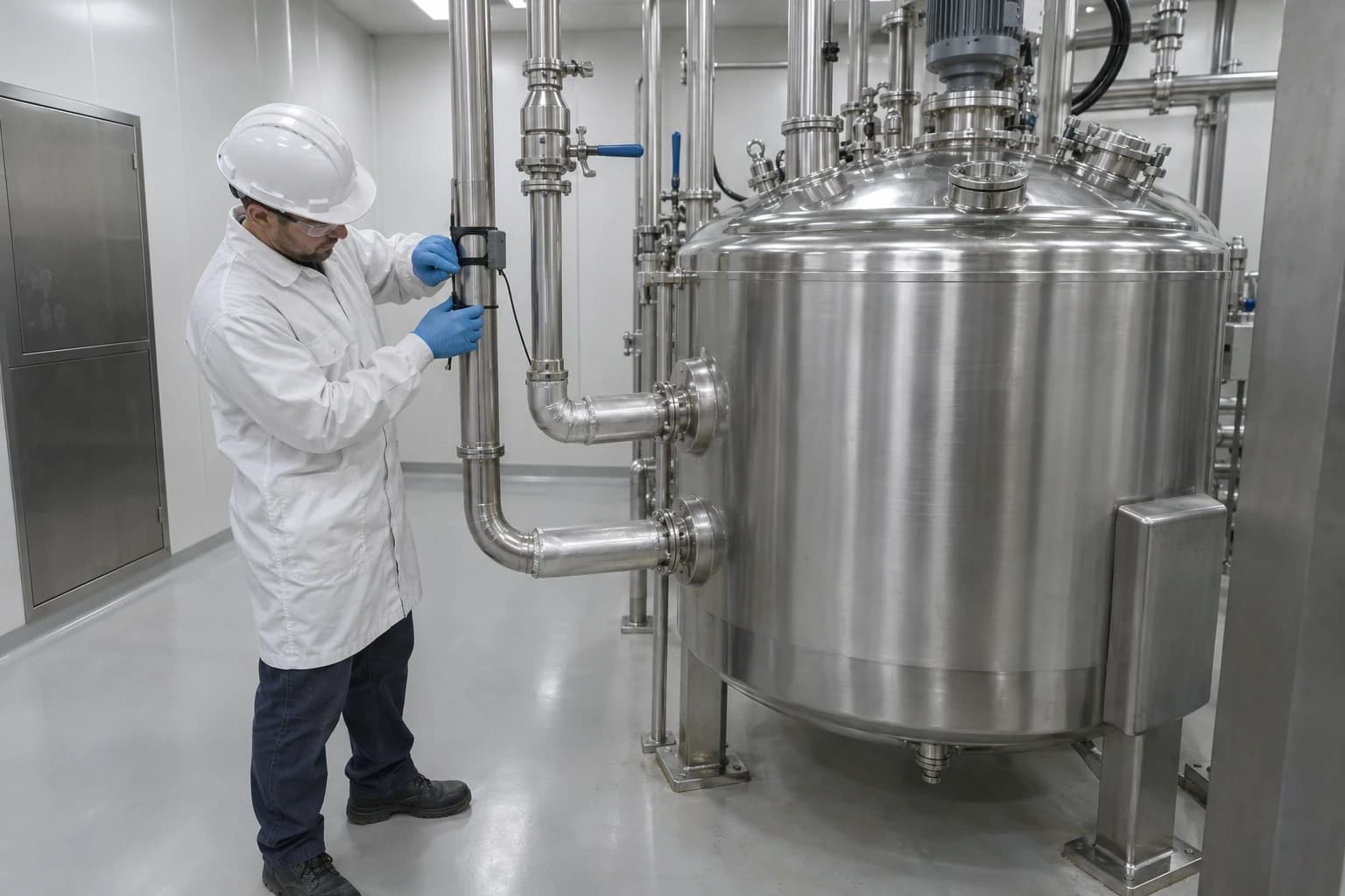
Pharmaceutical Heat Exchanger Network Design: Batch Timing
Batch-process studies estimate 21-43% of site heat demand is recoverable with thermal storage.
A pharmaceutical heat exchanger network is a set of exchangers, utility connections and, where needed, thermal storage that transfers heat between process streams while protecting product quality, hygienic design and validated operating conditions.
A reactor jacket may reject useful heat during a crystallisation hold at 10:00, while another batch needs heat for a solvent charge at 14:00. Although the temperatures may align, the timing does not. That gap is the central design constraint in pharmaceutical heat exchanger network design.
Batch production creates intermittent, recipe-led heating and cooling demands. Multiproduct facilities add variation through campaign lengths, cleaning cycles, product changeovers, batch-release delays and equipment availability. A heat exchanger network designed from average annual loads can therefore appear attractive on paper while offering little practical recovery on the plant floor.
Published work on a multiproduct batch plant found direct heat-recovery potential of 21 to 43% of site heat demand across daily time slices, with a maximum direct-recovery potential of 85 GJ per day. The case study was in textiles, not pharmaceuticals, but its finding applies to batch manufacturing: time-dependent stream availability determines the heat a real network can recover.
Why batch timing changes heat exchanger network design pharmaceutical projects
Conventional pinch analysis identifies hot streams that require cooling and cold streams that require heating. It establishes minimum utility targets and the temperature range in which heat can move between process duties.
That approach remains valuable in pharmaceutical plants. Batch timing adds a second requirement: hot and cold duties must occur at the same time, or the design needs a safe means of carrying heat across time.
A process stream has both temperature and duration
For batch heat integration, each process demand needs a time profile as well as inlet and target temperatures. Engineers should establish:
- Start and finish time for the heating or cooling step
- Heat-duty profile, including ramp, hold and discharge periods
- Batch frequency, recipe variants and campaign pattern
- Permitted changes to heating and cooling rates
- Whether the duty occurs in product-contact, utility or waste streams
- Cleaning-in-place, sterilisation-in-place and turnaround requirements
- Expected variation caused by production scheduling
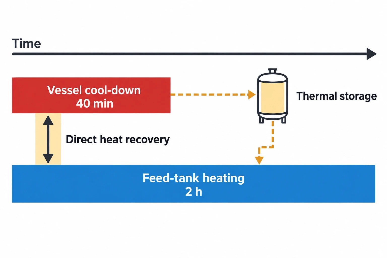
A vessel cool-down may provide a high-temperature heat source for only 40 minutes. A downstream feed tank might need a lower-temperature heating duty for two hours. The overlap, rather than peak temperature alone, dictates the exchanger duty.
Average loads can overstate recovery
Annual energy data can combine duties with no temporal overlap. It may show a large theoretical match between hot aqueous effluent and cold process-water demand, while production records show that the streams rarely coincide.
This matters during retrofits. A network that relies on an assumed batch sequence can lose recovery when planners alter a campaign, introduce a product or extend a hold time. Pharmaceutical heat exchanger network design therefore needs operating envelopes, not a single representative day.
A useful study model covers several credible schedules:
| Schedule case | Purpose in HEN design |
|---|---|
| High-throughput campaign | Tests peak simultaneous utility demand |
| Standard production week | Estimates typical recoverable heat |
| Low-volume or mixed-product week | Tests sparse batch overlap |
| Cleaning-intensive period | Captures CIP and SIP utility loads |
| Product changeover | Identifies recovery interruptions and isolation needs |
The aim is to identify matches that remain useful across the approved operating window, then quantify recovery that depends on a specific schedule.

Pinch analysis identifies the thermodynamic minimum energy requirement of your process — then designs the heat exchanger network to achieve it.
Building time slices for pharmaceutical batch heat recovery
Time-slice analysis divides the production period into intervals in which active streams and their duties remain defined. It makes the timing issue visible before detailed mechanical design begins.
Start with the recipe, not the utility meter
Utility meters identify the scale of steam, hot water, chilled-water and refrigeration use. They rarely show which batch operation caused a demand, whether the duty was product-critical or whether it can move in time.
The starting point should be the batch record and process description. Candidate duties include reactor heating and cooling, solvent recovery, distillation condensers, vacuum-system cooling, dryer-exhaust recovery, equipment-discharge cooling and hot water generated during cleaning.
Each stream record should distinguish process conditions from utility-side conditions. For example, a reactor jacket supplied with low-pressure steam has a process requirement defined by the product temperature trajectory, agitation, vessel geometry and allowable ramp rate. Steam pressure is a utility choice. Confusing the two can lead a study to preserve an existing steam duty when a lower-temperature recovered-heat source could perform the task.
Account for variable heat-transfer performance
Batch duties change as material properties change. Viscosity may rise during concentration. Crystallisation can change heat transfer. Vessel fill level and agitation speed alter the effective heat-transfer area and coefficient. Fouling can reduce duty during a campaign.
Design teams should use conservative, demonstrated heat-transfer data for critical matches. A network sized around clean-service performance can struggle to meet a validated batch time after fouling develops. The risk increases for viscous products, slurries, crystallising liquor and streams containing solids.
Exchanger selection must also respect cleanability. Plate-and-frame, shell-and-tube and double-tube designs present different inspection, gasket, pressure-drop and cleaning considerations. Product-contact service requires a design that supports the site’s contamination-control strategy and cleaning validation.
Do not treat all hot streams as interchangeable
A stream may carry enough heat for another duty while remaining unsuitable as the direct heating medium. Reasons include contamination risk, pressure differential, solvent content, batch-segregation requirements or inability to verify isolation after a leak.
An intermediate water or glycol loop can separate the two process sides. It gives the site greater control over fluid quality, pressure arrangement and isolation, but introduces an additional temperature approach and pumping duty that reduce the heat available to the final sink.
That trade-off should be assessed against the quality risk. In pharmaceutical heat exchanger network design, a direct match with a strong thermal case may be rejected because it weakens the contamination-control case.
Direct recovery, intermediate loops and thermal storage
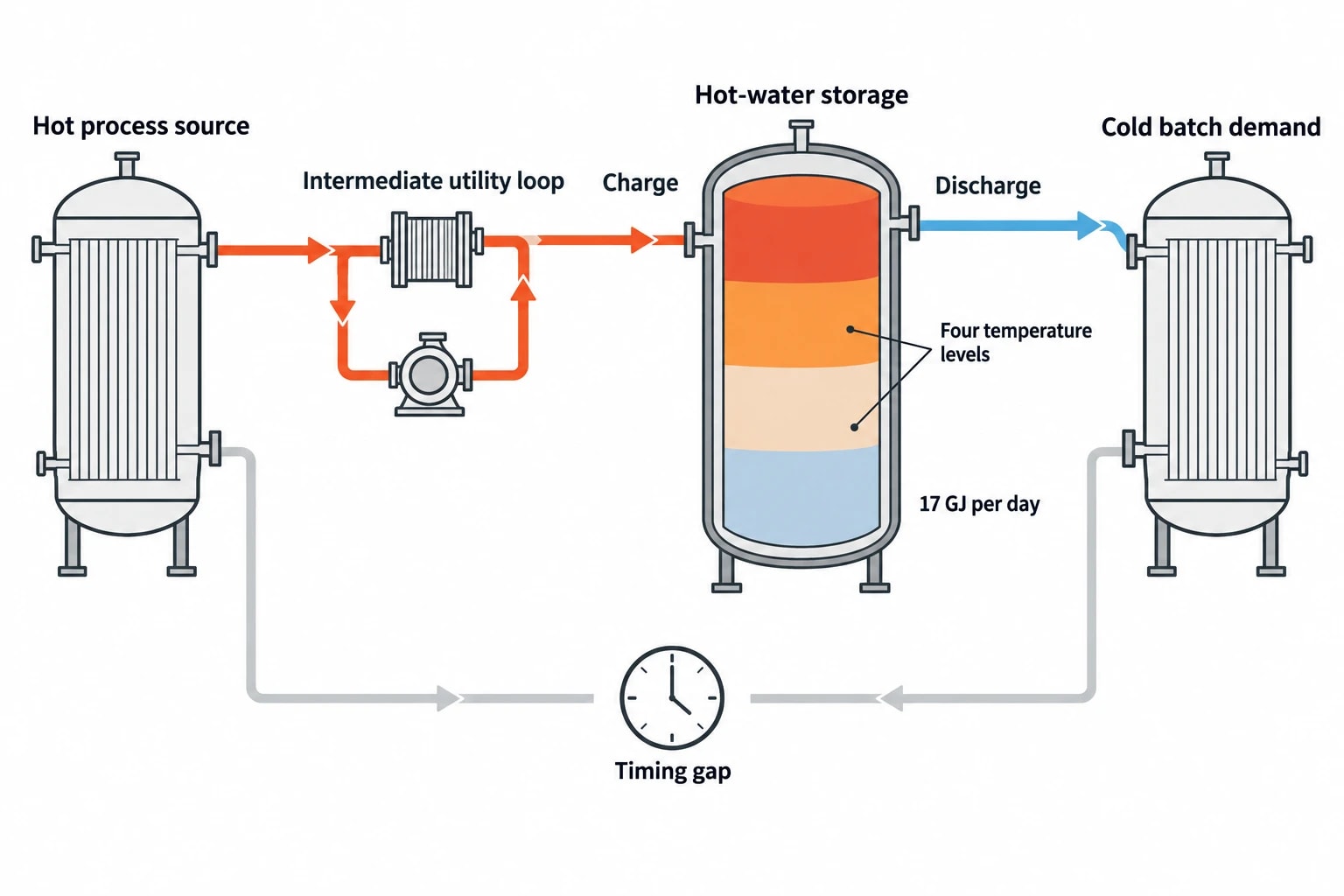
Three approaches can manage pharmaceutical process duties with different timing, temperature, contamination-risk and operational-flexibility requirements.
Direct heat recovery works where duties overlap
Direct recovery transfers heat from a hot process stream to a cold process stream through an exchanger while both are active. It usually gives the best temperature performance because there is no storage loop or intermediate exchanger.
Suitable applications may include:
- Condenser duty preheating a compatible incoming utility-water stream
- A hot discharge stream warming a process feed with sufficient timing overlap
- Heat recovered from a continuous operation supporting a batch utility demand
- A warm return stream preheating cleaning water where quality controls permit
The physical network needs bypasses, control valves and defined utility backup. Batch equipment must retain the ability to meet approved time-temperature conditions when the recovered source is unavailable. Recovery should reduce utility consumption without creating a dependency that compromises the batch.
Intermediate loops create separation and flexibility
An intermediate closed loop allows heat transfer between streams that require greater physical separation. It can also collect heat from intermittent sources and deliver it to several sinks.
The loop medium, operating temperature, pressure, filtration, venting and maintenance regime require explicit design decisions. An intermediate loop can become a contamination vector if it connects to product-contact barriers without appropriate engineering controls. Designers should consider credible leak direction, differential pressure, detection arrangements and isolation strategy for each exchanger.
A loop also provides a clear metering point. Measuring temperature, flow and recovered thermal duty supports performance verification and helps operations distinguish a process disturbance from exchanger fouling.
Thermal storage bridges timing gaps
Thermal energy storage carries useful heat from one time slice to another. For pharmaceutical sites, sensible hot-water storage is often easier to evaluate than product-side storage because it can sit on an intermediate utility loop. The store charges when a hot source is available and discharges when a cold demand begins.
The batch-process research cited above found that a four-temperature-level storage arrangement offered an additional 17 GJ per day beyond the direct network in its case study. That result is site-specific. It demonstrates why storage should be tested after direct matches are identified, rather than treated as a default addition.
Storage selection should consider:
- Required delivery temperature and minimum usable temperature
- Duration and variability of the timing gap
- Heat losses during the storage period
- Available footprint and structural loading
- Cleaning and water-quality management
- Pumping, control and backup utility requirements
- Whether production schedules can shift to improve direct recovery first
Scheduling changes can sometimes create more recoverable heat than additional exchanger area. Moving a non-critical preheat step into another batch’s cool-down period may create direct overlap. Production, quality and engineering functions must jointly assess whether the schedule change affects validated process conditions, material hold times or cleaning arrangements.

Pinch analysis identifies the thermodynamic minimum energy requirement of your process — then designs the heat exchanger network to achieve it.
GMP change control for heat exchanger network retrofits
A new exchanger can alter heating rates, cooling profiles, utility quality and the response to process upsets. These are quality-system matters as well as energy matters.
EU GMP EudraLex Volume 4, Annex 15 applies qualification and validation principles to facilities, equipment, utilities and processes used in medicinal-product manufacture. It expects planned changes that may affect product quality to be formally documented and assessed for their effect on validated status or the control strategy.
Define the quality impact before selecting equipment
The change-control assessment should begin while engineers still have alternatives. It should examine the proposed heat source, receiver, utility interfaces, product-contact boundaries and control philosophy.
Questions for the assessment include:
- Does the retrofit alter a critical process parameter or approved operating range?
- Could an exchanger leak introduce utility fluid or another process stream into product?
- Does the change alter heating or cooling ramp rates, hold times or endpoint control?
- Are cleaning, sanitisation or sterilisation cycles affected?
- Does the new arrangement create dead legs, inaccessible surfaces or difficult-to-drain sections?
- Can instruments demonstrate the required temperature and flow performance?
- What happens if the recovered-heat source fails mid-batch?
The answers inform the qualification strategy. Design qualification may confirm that specified materials, drainability, pressure ratings, instrumentation and isolation arrangements meet user requirements. Installation qualification confirms that installed equipment and documentation match the approved design. Operational and performance qualification then demonstrate control and reproducibility under conditions relevant to the process.
Annex 15 revision work raises the importance of early assessment
In January 2026, the EMA and PIC/S issued concept paper EMA/INS/GMP/20217/2026 on revising Annex 15. The consultation closed in April 2026. The paper proposed a targeted update, including an extension of scope to active-substance manufacturers and consideration of the revised ICH Q9 quality-risk-management guideline.
A concept paper does not replace the current annex. Retrofit teams should maintain a clear, risk-based record showing why the heat-recovery design preserves the control strategy and how the site will verify continued performance.
Safety, pressure systems and maintainability
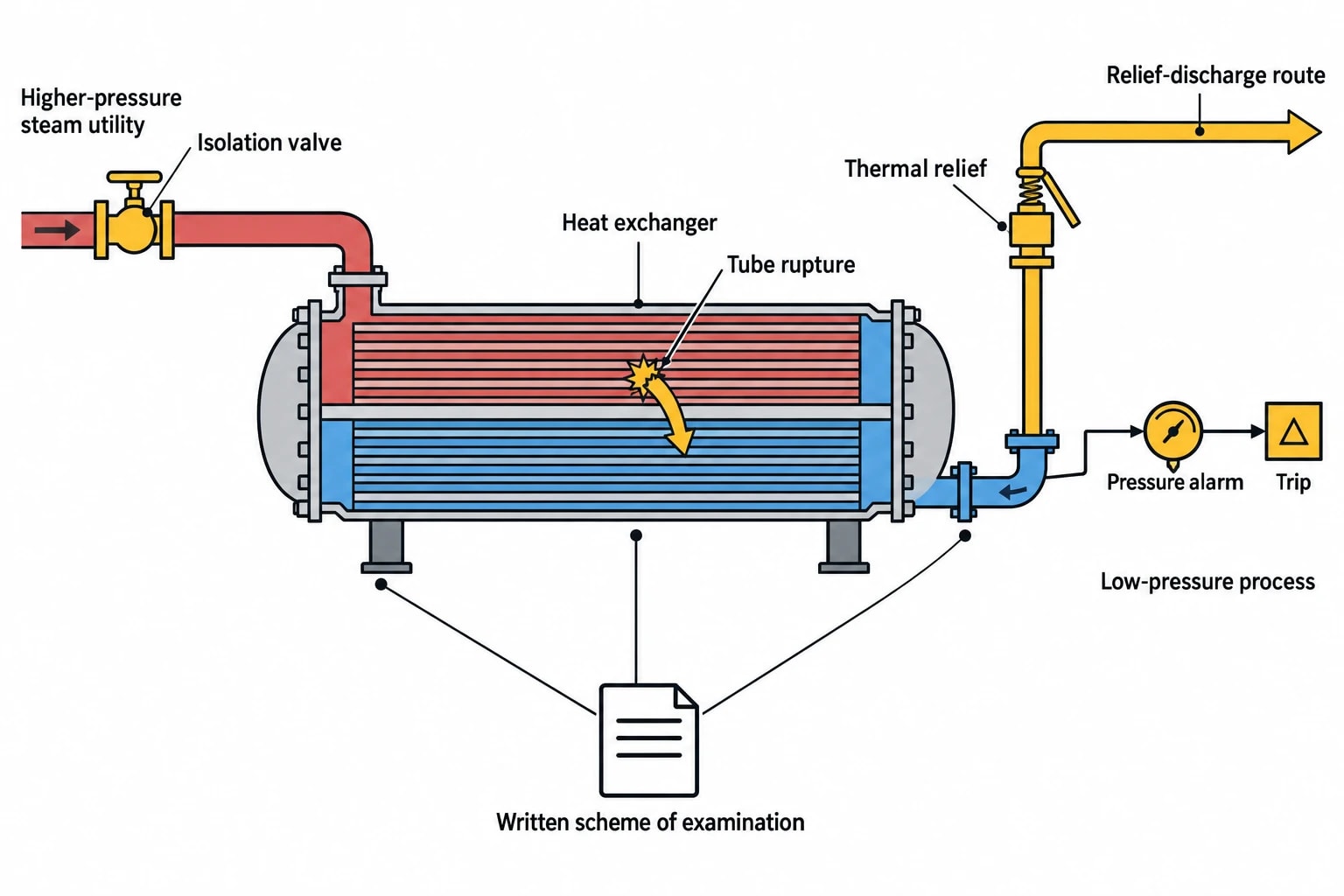
Heat recovery increases the number of exchangers, valves, instruments and connections. Each adds potential failure modes. HSE guidance for heat exchangers addresses corrosion, erosion, overheating, overpressurisation, structural failure, vibration and defective equipment. Inspection, leak detection, relief systems, alarms, trips, operating procedures and isolation form part of the relevant control measures.
Assess PSSR 2000 at design stage
The Pressure Systems Safety Regulations 2000 apply to pressure systems used at work and aim to prevent injury from stored-energy failure. Steam at any pressure is a relevant fluid. The regulations also cover compressed or liquefied gases above 0.5 bar above atmospheric pressure and pressurised hot water above 110 °C.
Where equipment forms part of a qualifying pressure system, a written scheme of examination must be in place before use and the system examined in accordance with that scheme. The scheme should reflect the added exchanger, associated pipework, protective devices and operating conditions introduced by the retrofit.
The pressure assessment should include blocked-in liquid expansion, tube-side and shell-side design pressures, thermal relief, relief-discharge route, credible cross-contamination from tube rupture and the effect of control-valve failure. A lower-pressure process side may need protection from a higher-pressure utility side, particularly where steam, pressurised hot water or nitrogen blanketing connects to equipment in a recovery loop.
Design for inspection and controlled maintenance
Thermal duty has value only while the exchanger can operate safely and hygienically. Access for inspection, gasket replacement, leak testing and cleaning must be built into the layout. Isolation points should permit maintenance without creating unmanageable stagnation volumes or forcing long production outages.
Performance monitoring should compare measured recovered duty with expected duty for the active batch step. A gradual decline can indicate fouling, reduced flow, control-valve problems or an altered recipe. Trend review supports planned maintenance and protects the network’s business case.
A practical sequence for batch HEN synthesis
Batch timing should shape the study from the first data request through to qualification.
- Map process streams from recipes, batch records and utility data.
- Record temperatures, duties, durations, operating limits and product-contact status.
- Build time slices for representative campaigns, cleaning periods and product mix.
- Set utility targets and identify direct matches with adequate time overlap.
- Test schedule changes that preserve approved process requirements.
- Evaluate intermediate loops and thermal storage for remaining timing gaps.
- Complete contamination-control, pressure-system and maintainability assessments.
- Develop the GMP change-control and qualification plan alongside detailed design.
- Commission with recovery measurement, utility-backup testing and defined performance-acceptance criteria.
This article reflects the independent analysis and editorial opinion of EnerTherm Engineering. Product names, trademarks, and brands mentioned belong to their respective owners. EnerTherm Engineering is not affiliated with, endorsed by, or a licensee of any third-party software or product mentioned unless explicitly stated.

Managing Director — EnerTherm Engineering
Dr. François Pierrel is Managing Director of EnerTherm Engineering with over two decades of expertise in thermal design, heat transfer, and industrial energy optimisation. He holds a PhD in Heat Transfer from Cranfield University and a Post-Doctorate from Heriot-Watt University.
