Why Pinch Point Heat Exchanger Networks Cut Utility Demand
How ΔTmin separates above- and below-pinch regions in retrofit design.
A pinch point heat exchanger network is a process heat-recovery system designed around the temperature constraint that sets the minimum possible hot- and cold-utility demand. Ipieca reports that pinch-analysis projects in oil-refining applications can reduce purchased heating fuel by 8% to 25%, depending on the starting arrangement and available heat recovery.
A process plant often contains both sides of an expensive thermal problem. One stream needs cooling before storage, separation or downstream treatment. Another needs heating before reaction, distillation, evaporation, drying or pasteurisation. A conventional heat exchanger network can still send the first stream to cooling water while raising steam demand for the second.
Pinch analysis identifies where direct exchange is thermodynamically feasible and where it is constrained by the selected minimum temperature approach, ΔTmin. A pinch point heat exchanger network then arranges exchangers so recovered process heat does as much work as possible before utilities fill the remaining gap.
For UK chemical, food and beverage, pharmaceutical, refinery and manufacturing sites, the value is practical. Lower steam and fuel demand reduces operating costs and associated emissions. Lower cooling duty can also ease pressure on cooling towers, chilled-water systems and cooling-water infrastructure. The work is most effective when engineers treat the pinch as a design boundary, rather than a theoretical result to be ignored during detailed engineering.
What is the pinch point in a heat exchanger network?
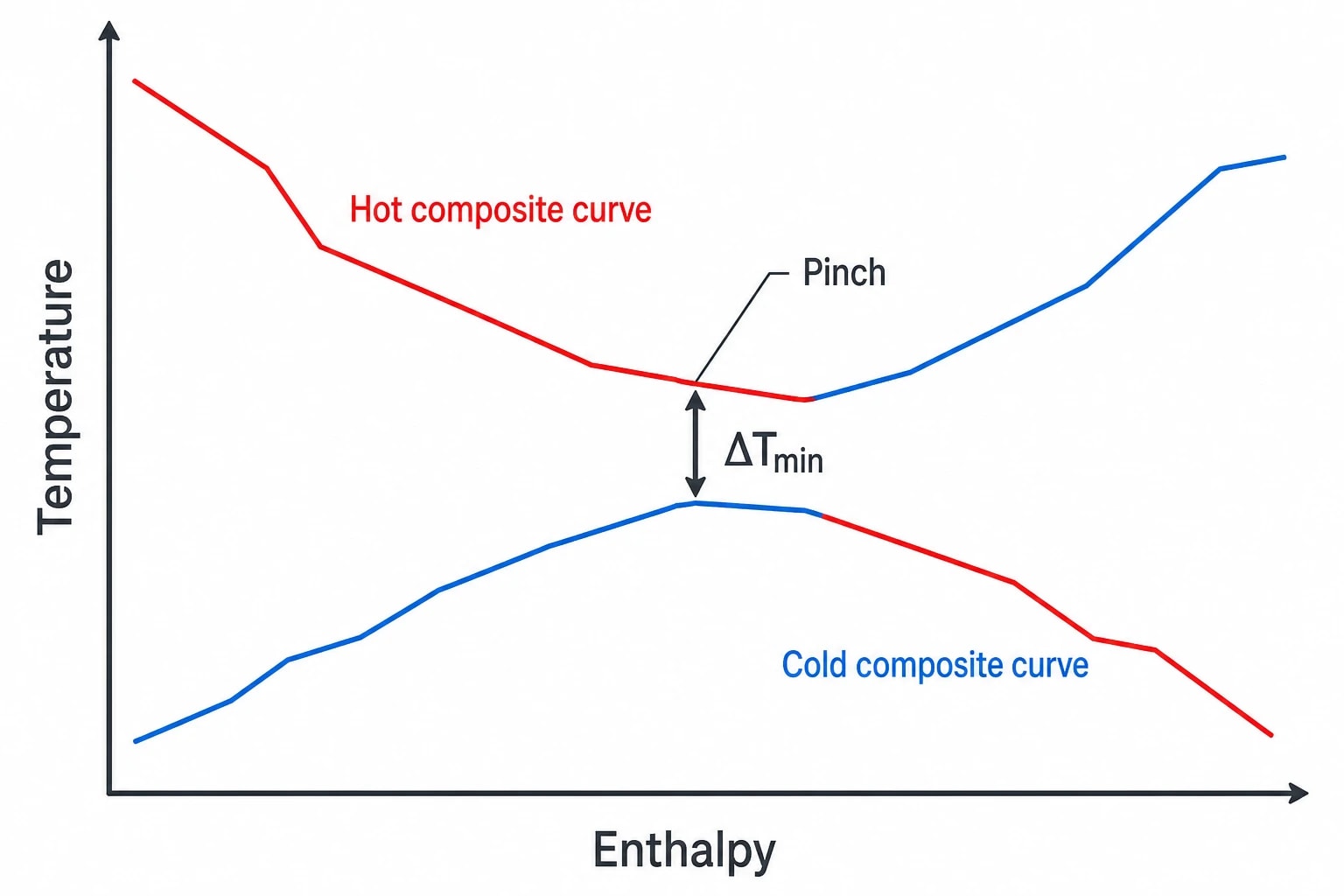
The pinch is the point of closest thermal approach between combined hot-stream and cold-stream demands after applying the selected ΔTmin. It is where the process has least flexibility to move heat from hot streams to cold streams.
Hot streams, cold streams and process duty
A hot stream releases heat as it cools. Examples include reactor effluent, distillation bottoms, hot product, compressor discharge, flue gas and condensate. A cold stream requires heat as it warms, vaporises or reaches its required operating temperature. Feedstocks, boiler-feed water, wash solutions, evaporation feeds and reactor feeds commonly fall into this category.
Pinch analysis starts with reliable stream data:
- Supply and target temperatures
- Mass flow or heat-capacity flowrate
- Phase changes and latent duties
- Pressure and operating constraints
- Permitted pressure drop
- Fouling behaviour and cleanability requirements
- Batch timing, where the plant does not run continuously
- Existing exchanger duties, bypasses and utility loads
The analysis combines these duties into energy targets. It does not assume that any hot stream can heat any cold stream. Temperature driving force, process safety, contamination risk, metallurgy, controllability and production requirements still determine whether a proposed match is viable.
Why ΔTmin matters
ΔTmin is the minimum temperature difference accepted between hot and cold process streams in an exchanger network. It represents an economic choice.
A smaller ΔTmin permits more heat recovery and reduces utility demand. It also tends to require more heat-transfer area, increasing exchanger capital cost and exposure to fouling, pressure drop and maintenance complexity. A larger ΔTmin usually reduces exchanger area and initial cost, but leaves more duty for steam, fuel, cooling water or refrigeration.
Ipieca’s 2022 pinch-analysis guidance describes ΔTmin as an economic trade-off between exchanger capital cost and utility cost. This matters in retrofit studies. Selecting a low ΔTmin solely because it produces an attractive energy target can create an impractical modification list. Selecting a high value to minimise capital expenditure can discard worthwhile fuel savings over the asset’s life.
In detailed work, engineers may use different practical temperature approaches for different service types. Condensing steam, cooling water, refrigeration and process-to-process exchange each have different economics and operational limits. The chosen target must remain consistent with exchanger type, fouling allowance and duty under normal and credible upset conditions.

Pinch analysis identifies the thermodynamic minimum energy requirement of your process — then designs the heat exchanger network to achieve it.
How a pinch point heat exchanger network reduces utility demand
A pinch point heat exchanger network cuts utility demand by preserving heat recovery on the correct side of the pinch. The pinch divides the problem into two regions with distinct energy requirements.
Above the pinch, the process needs a net external heat input. Below it, the process has a net heat surplus requiring external cooling. Process-to-process exchange should satisfy these duties within their respective regions before utilities are introduced.
The three pinch-design rules
At the utility targets associated with the selected ΔTmin, a minimum-energy heat exchanger network follows three rules:
-
Do not transfer heat across the pinch.
-
Do not use external cooling above the pinch.
-
Do not use external heating below the pinch.
These rules follow from the energy balance around the two pinch regions.
External cooling above the pinch removes heat that a cold stream in that region needs. The plant must replace it with additional hot utility. External heating below the pinch adds heat to a region that already has a net surplus, requiring additional cold utility.
Cross-pinch heat transfer has the same effect. When an exchanger moves heat from the above-pinch region to the below-pinch region, it deprives the heat-deficit region of recoverable duty while adding duty to the heat-surplus region. Hot- and cold-utility requirements both rise by the amount of cross-pinch heat transfer.
A simple operating consequence
Consider a plant that cools a hot process stream with cooling water above the pinch while heating a separate cold process stream with steam above the same pinch. If the two streams have compatible temperatures, a process exchanger may replace part of both duties.
The benefit is not limited to fuel. The modification can reduce boiler load, condensate generation, cooling-tower fan and pump consumption, make-up water use and blowdown. Actual site benefit depends on utility-generation efficiency, distribution losses, cooling-system configuration and production profile.
A network can still use utilities. The pinch rules place them where they cause the least additional demand. Steam or fired heat belongs above the pinch when the process target requires it. Cooling water, air cooling, chilled water or refrigeration belongs below it when the process has residual heat to reject.
Building the heat-recovery target before choosing exchangers
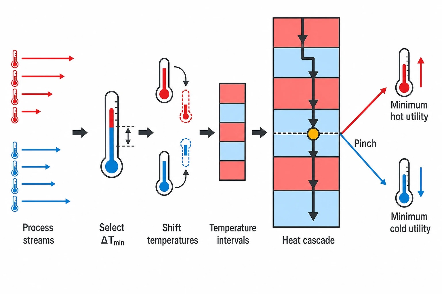
The energy target should come before exchanger selection. A design that begins with familiar equipment locations or a preferred stream pairing can preserve historical utility demand rather than identify the minimum achievable requirement.
Composite curves and the problem table
Engineers commonly use composite curves or the problem-table algorithm to identify the pinch and calculate minimum hot- and cold-utility targets. These methods aggregate the temperature and heat-capacity characteristics of all selected process streams.
Temperature shifting applies half of the selected ΔTmin to each side of the thermal problem. Hot-stream temperatures are reduced by half the approach, while cold-stream temperatures are increased by half. The shifted streams can then be compared directly without violating the actual minimum temperature approach.
The resulting heat cascade shows whether each temperature interval has a surplus or deficit of recoverable heat. The point at which the cascade reaches its limiting value identifies the pinch. The addition required to keep the cascade non-negative defines the minimum hot-utility target. The final cascade balance defines the minimum cold-utility target.
This target is a thermodynamic benchmark. It assumes the stream data, operating conditions and selected ΔTmin are valid. It does not guarantee that a real plant can reach the target without excessive exchanger area, difficult piping routes, unacceptable pressure loss or poor operability.
Choosing the correct design case
A useful pinch study separates cases that differ materially in operation:
- Normal high-throughput production
- Lower-rate campaigns
- Different feed compositions
- Seasonal cooling-water temperatures
- Start-up and shutdown arrangements
- Batch heating and cooling schedules
- Fouled and clean exchanger performance
- Parallel-train operation
A network designed only around average annual data can perform badly under the conditions that set utility peaks. For example, a crude-preheat train may have different feasible recovery when crude properties, throughput, furnace operation or exchanger fouling changes. Food and beverage plants can face similar variation across product campaigns, cleaning cycles and seasonal utility temperatures.
Utility levels matter as well as utility quantity
The hot-utility target should distinguish between temperature levels. A process may need low-pressure steam for one service and medium-pressure steam for another. A high-temperature furnace duty cannot automatically be replaced by low-grade waste heat, even when annual energy totals appear favourable.
The same principle applies to cooling. Cooling water, air coolers, chilled water and refrigeration have different costs and temperature capabilities. A pinch point heat exchanger network should therefore match recovered heat to the cold-stream target temperature before counting it as a utility reduction.

Pinch analysis identifies the thermodynamic minimum energy requirement of your process — then designs the heat exchanger network to achieve it.
Designing above and below the pinch
A practical network synthesis begins at the pinch and moves outwards. This prevents engineers from consuming valuable heat in a location that later creates an avoidable utility requirement.
Above-pinch design
Above the pinch, each cold stream needs heat. Process exchangers should match hot-stream heat availability to cold-stream demand without sending heat across the pinch. Hot utility supplies the remaining deficit.
Stream matching requires attention to heat-capacity flowrates and feasible terminal temperature differences. A match that looks attractive in a target calculation may be unsuitable if it forces a temperature crossover, demands excessive area or leaves insufficient controllability at low throughput.
For services involving phase change, engineers also need to examine pressure effects, condensation behaviour and temperature stability. A condensing vapour can offer an excellent near-isothermal heat source, but its availability may depend on column pressure, compressor operation or batch timing.
Below-pinch design
Below the pinch, the process has excess heat. Cold streams should absorb as much as feasible before external cooling removes the remainder.
This is where existing plants frequently reveal wasted opportunity. A product cooler, trim cooler or hot-effluent cooler may reject useful heat while another low-temperature process stream receives steam or electric heating. The proposed recovery route must still protect product quality, hygiene, hazardous-area requirements and each stream’s required final temperature.
A final cooler may remain necessary for control or to meet a product specification. Ipieca describes an upstream separation and stabilisation case where pinch analysis indicated that a conventional product cooler could be eliminated on an energy basis, while recognising that a reduced trim cooler could still be needed to maintain product specification and controllability. The retrofit lesson is clear: a theoretical utility target must be translated into a controlled plant design.
Retrofitting an existing heat exchanger network around the pinch
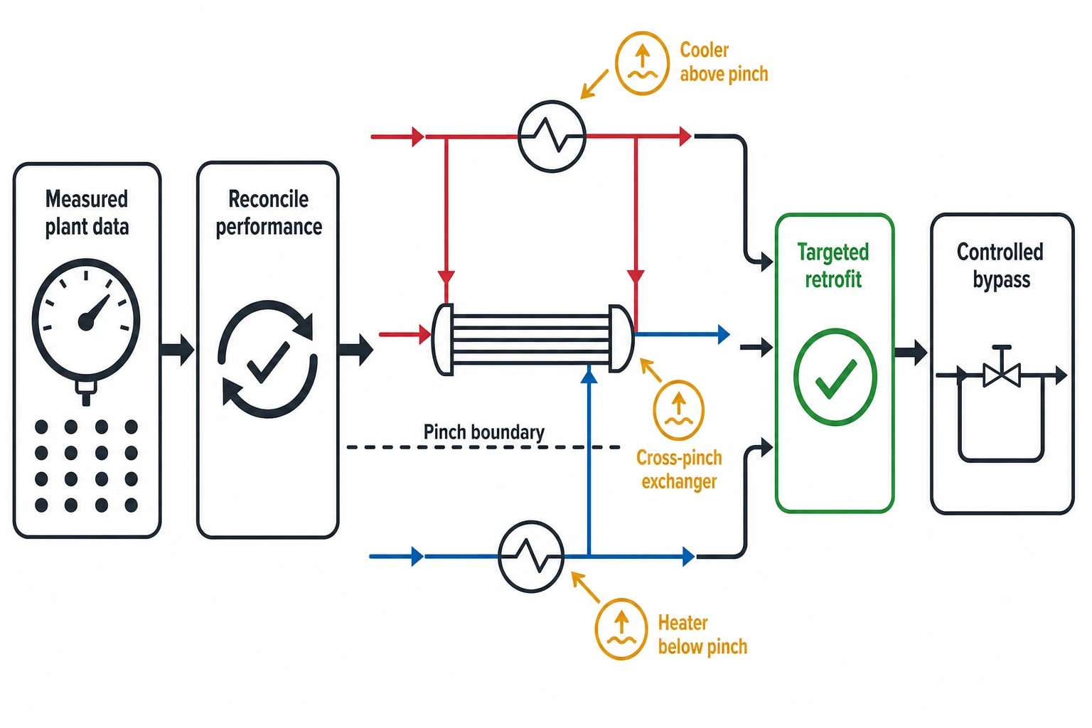
Retrofit work rarely begins with an empty plot and unrestricted pipe routing. Existing exchangers have fixed shell-and-tube arrangements, fouling histories, nozzle loads, control valves, plot constraints and shutdown windows. The aim is to identify changes that secure substantial utility savings with acceptable capital cost and operational risk.
Start with measured performance
Design data sheets are a necessary starting point, but they should not be treated as current operating truth. A retrofit investigation benefits from measured temperatures, flows, pressures and utility use over representative production periods.
Plant teams should reconcile:
- Stream temperatures against calibrated instruments
- Flow data against mass balances and production records
- Exchanger duties against measured utility consumption
- Pressure losses against available pump and compressor head
- Fouling margins against inspection history and performance trends
- Bypasses and control positions against normal operator practice
A preheat train that appears to have spare area on paper may have lost performance through fouling, maldistribution, tube plugging or a bypass left open for operability. A new exchanger can also underperform if fouling duty is added without improving upstream solids control, cleaning procedures or velocity management.
Identify cross-pinch exchanges and misplaced utilities
The first retrofit candidates are often existing cross-pinch exchangers, coolers above the pinch and heaters below it. Each creates avoidable utility demand in the target case.
The correction does not always mean removing equipment. Engineers may reroute streams, alter exchanger sequencing, add a new match, change a control arrangement, restore fouled exchanger performance or use an existing spare shell. A smaller change can unlock a larger network benefit if it releases heat for the constrained side of the pinch.
Ipieca cites crude-unit and refinery applications as established uses of pinch analysis. Its 2022 compendium reports a crude-preheat-train retrofit case in which exchanger rearrangement combined with economic analysis achieved 8% total energy savings against the base case. Results vary widely by plant condition, utility prices, constraints and the extent of existing recovery, so a site-specific target remains essential.
Test operability before approving the scheme
A pinch-compliant network can still create control problems if the design team ignores disturbances. Feed-rate changes, exchanger fouling, changes in reaction duty and utility-pressure swings all alter temperatures and duties.
The operating review should test:
- Minimum and maximum production rates
- Feed and product specification changes
- Start-up heat-up sequences
- Shutdown cooling requirements
- Control-valve authority
- Bypass requirements
- Thermal expansion and mechanical stress
- Cleaning isolation and maintenance access
- Consequences of exchanger leakage or loss of a utility system
Heat recovery should not remove the degrees of freedom needed to keep a process safe and on specification. In some cases, a controlled bypass or small trim-utility exchanger is a prudent part of the design, even though it prevents operation exactly at the theoretical minimum at every moment.
Pinch analysis within UK energy-management practice
Pinch analysis converts process data into an energy target and a ranked set of engineering changes. That makes it a useful input to structured energy management, capital planning and industrial decarbonisation work.
Linking the network to ISO 50001
ISO 50001:2018 provides requirements and guidance for an energy-management system. ISO published ISO 50001:2018/Amd 1:2024, covering climate-action changes, in February 2024.
For an energy manager, the pinch target can support the energy review by identifying significant energy uses tied to hot and cold utilities. The implemented network should then be monitored through measured steam, fuel, electricity and cooling consumption, normalised for throughput and relevant production variables.
The energy-performance indicator should reflect the modification’s stated purpose. A boiler-fuel indicator alone may miss a cooling penalty. A better measurement plan can track hot-utility reduction, cold-utility reduction, production rate, relevant feed properties and process temperatures at the changed exchangers.
UK evidence and investment priorities
The Department for Energy Security and Net Zero published report RAF018/2324, Updating evidence on energy efficiency potential for UK industry, on 24 March 2026. The report updates the 2015 industrial decarbonisation and energy-efficiency roadmaps and focuses on energy-efficiency measures within industrial processes.
That context supports a disciplined approach to heat-exchanger-network projects. A pinch study should move beyond a generic waste-heat claim and identify the duty, temperature range, utility displaced, modification required and conditions under which savings hold. Plant managers can then compare the project against alternatives using the site’s own fuel, electricity, water, emissions and shutdown-cost assumptions.
The practical decision
A pinch point heat exchanger network reduces utility demand because it protects the temperature-constrained heat recovery available to the process. The selected ΔTmin sets the trade-off between exchanger investment and lifetime utility cost. The pinch rules then prevent design choices that force extra heating and cooling.
The strongest projects combine a credible pinch target with measured plant data, exchanger-condition assessment, operability testing and a post-commissioning measurement plan. That turns heat integration from a diagram exercise into a durable reduction in steam, fuel and cooling demand.
This article reflects the independent analysis and editorial opinion of EnerTherm Engineering. Product names, trademarks, and brands mentioned belong to their respective owners. EnerTherm Engineering is not affiliated with, endorsed by, or a licensee of any third-party software or product mentioned unless explicitly stated.

Managing Director — EnerTherm Engineering
Dr. François Pierrel is Managing Director of EnerTherm Engineering with over two decades of expertise in thermal design, heat transfer, and industrial energy optimisation. He holds a PhD in Heat Transfer from Cranfield University and a Post-Doctorate from Heriot-Watt University.
