Thermal Design Simulation Resolves Batch LMTD Loss
Using DynHeat and dynamic modelling to resolve batch LMTD degradation.
A thermal design simulation is a thermodynamic modelling methodology used to predict, analyse, and optimise heat transfer rates, temperature profiles, and fluid dynamics within industrial thermal systems. In energy-intensive sectors, batch processing operations often experience severe throughput bottlenecks because design calculations rely on static, steady-state heat transfer assumptions. When a chemical batch reactor cycles through heating and cooling phases, the temperature driving force decays over time, causing Logarithmic Mean Temperature Difference (LMTD) loss. For a typical multi-product chemical facility, neglecting this transient LMTD decay during equipment sizing can prolong batch cycles by up to 35%, leading to significant loss of annual production capacity and excess utility consumption.
Thermodynamic Principles of Batch LMTD Loss
Dynamic Temperature Progression in Batch Vessels
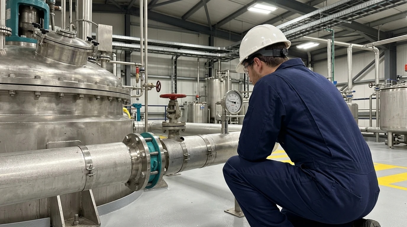
In a typical batch operation, a fixed mass of process fluid is charged into a vessel and heated or cooled to a target temperature. This is achieved by circulating a utility fluid, such as steam, hot water, or thermal oil, through an external jacket or internal coil. At the start of the heating cycle, the temperature difference between the hot utility and cold process fluid is at its maximum, driving rapid heat transfer.
As the cycle progresses, the batch fluid temperature rises, narrowing the temperature difference between the utility stream and the process fluid. Because the process is transient, the temperature profiles are functions of time rather than spatial position. This continuous temperature rise reduces the driving force across the heat exchanger surface, resulting in a dynamic temperature progression.
Mathematical Decay of the LMTD Driving Force
The Logarithmic Mean Temperature Difference (LMTD) measures the effective thermal driving force across a heat exchanger. For a standard exchanger, the LMTD is calculated as follows:
LMTD=ln(ΔT2ΔT1)ΔT1−ΔT2Where:
- LMTD is the Logarithmic Mean Temperature Difference in °C.
- ΔT1 is the temperature difference between the hot and cold streams at one end of the heat exchanger in °C.
- ΔT2 is the temperature difference between the hot and cold streams at the other end of the heat exchanger in °C.
In batch operations, terminal temperature differences change continuously. As the batch fluid temperature approaches that of the heating medium, the value of ΔT2 approaches zero. This convergence causes the LMTD to decay logarithmically, leading to a non-linear drop in the heat transfer rate.
Impact on Equipment Sizing and Process Cycle Times
The heat transfer rate within any exchanger depends on the following physical relationship:
Q=U⋅A⋅LMTD⋅FWhere:
- Q is the instantaneous heat transfer rate in W.
- U is the overall heat transfer coefficient in W/(m²·K).
- A is the physical heat transfer area in m².
- F is the dimensionless LMTD correction factor.
Sizing a batch heat exchanger using steady-state assumptions often relies on a constant LMTD based on initial or average process temperatures. However, because the actual LMTD decays continuously, the real heat transfer rate drops over time. To transfer the required thermal energy within the target cycle time, the physical heat transfer area must be larger than a steady-state calculation suggests. Underestimating this degradation results in undersized exchangers, leading to prolonged batch durations, process bottlenecks, and excess utility consumption.

Map every energy and material flow in your process with detailed heat and mass balance calculations — the foundation for any optimisation or design project.
Limitations of Steady-State Pinch Analysis in Batch Operations
Why Continuous Pinch Methods Fail in Batch Networks
Pinch analysis is a standard engineering method used to optimise heat exchanger networks (HENs) in continuous manufacturing plants by constructing grand composite curves of hot and cold process streams. However, classic pinch analysis assumes that all thermal streams are continuous and coexist.
In batch facilities, streams are intermittently available and operate at different times. Applying continuous pinch methods to batch plants leads to physically unfeasible heat exchanger designs, as hot and cold streams may not be present simultaneously to exchange energy.
Time-Slicing and Multi-Period Operations
To adapt pinch analysis for batch processes, engineers traditionally divide the operational schedule into discrete intervals—a method known as time-slicing or multi-period operation. During each slice, the system is assumed to be in a pseudo-steady state, allowing standard pinch calculations.
While this approach handles time-dependent stream availability, it fails to model the continuous temperature variations within individual batches. When a hot batch reactor jacket heats a cold feed tank, both temperatures change dynamically. This causes rapid, non-linear LMTD degradation that discrete time slices cannot resolve.
The Requirement for Transient Thermal Modelling
To resolve the limitations of time-slicing, engineers employ transient thermal design simulation. Transient models represent heat exchangers and reactors as systems of differential algebraic equations (DAEs). These systems account for equipment thermal mass, changing fluid velocities, and continuous LMTD decay. Simulating the full transient behaviour allows engineering teams to predict temperature profiles accurately and optimise heat exchanger network configurations.
| Operational Parameter | Steady-State Simulation Approach | Dynamic Thermal Simulation Approach |
|---|---|---|
| Time Dependency | Assumes constant temperatures and flow rates | Models parameters as time-variant trajectories |
| LMTD Representation | Fixed LMTD value based on initial or average values | Logarithmically decaying LMTD driving force |
| Equipment Sizing | Often results in undersized heat transfer areas | Optimises physical surface area to prevent bottlenecks |
| Pinch Analysis | Continuous pinch method; assumes simultaneous streams | Integrates transient scheduling and dynamic pinch curves |
| Utility Switching | Manual or heuristic-based utility cut-offs | Dynamic optimisation (e.g., DynHeat) to recommend utility cut-off points |
| Mechanical Integration | Static stress and temperature assumptions | Generates transient metal temperatures for fatigue analysis |
Overcoming Transient Bottlenecks with Dynamic Optimisation: The DynHeat Method
Core Mechanics of the DynHeat Framework
The DynHeat framework is a mathematical method designed for the synthesis of heat exchanger networks in dynamic batch processes. Developed to address time-dependent stream progressions, DynHeat uses dynamic optimisation to construct optimal network topologies.
Rather than treating stream temperatures as static variables, the DynHeat algorithm models them as continuous, time-variant trajectories. This allows the simulation to optimise heat recovery while accounting for continuous LMTD decay.
Balancing Energy Recovery and Batch Cycle Duration
In batch operations, a trade-off exists between the quantity of heat recovered and the cycle duration. As heat integration increases, the temperature of the receiving batch fluid rises, which degrades the LMTD and slows heat transfer towards the end of the cycle. This slower rate can prolong batch duration.
Process engineers utilise the DynHeat method to perform multi-objective optimisation to resolve this trade-off. It balances operational energy savings against heat exchanger capital costs and the economic penalty of longer cycles, defining the exact operating window for optimum profitability.
Mathematical Representation of Transient Thermal Networks
The DynHeat framework models the network using mixed-integer non-linear programming (MINLP) coupled with dynamic differential equations. The optimisation algorithm evaluates how varying heat exchanger surface areas and bypass operations affect the dynamic temperature progression. This mathematical rigour allows thermal specialists to identify the optimal moments to suspend heat recovery and recommend when to engage external utility streams, preventing cycle time extensions caused by severe LMTD loss.

Map every energy and material flow in your process with detailed heat and mass balance calculations — the foundation for any optimisation or design project.
Sector-Specific Challenges: Food, Chemicals, and Refining
Food and Beverage: Managing Multi-Zone Thermal Profiling
In the food and beverage sector, batch thermal processing is widely used for pasteurisation, sterilisation, and cooking. Maintaining precise thermal profiles is critical for product quality, safety, and Hazard Analysis Critical Control Point (HACCP) compliance.
If a batch pasteuriser experiences LMTD loss, the heating rate decays, making it difficult to maintain specific holding temperatures. Transient thermal design simulation allows engineers to model multi-zone thermal profiles within jacketed vessels, ensuring the target thermal dose is delivered on schedule without causing localised overheating or product degradation.
Chemical and Pharmaceutical Processing: Reactor Kinetics Integration
For chemical and pharmaceutical manufacturers, batch reactors must handle highly dynamic thermal loads driven by reaction kinetics. Exothermic reactions release heat that must be rapidly removed, while endothermic processes require controlled thermal input. Because reaction rates depend heavily on temperature, any heat transfer delay caused by LMTD degradation can lead to incomplete reactions, reduced yields, or thermal runaway.
The reactor heat generation rate is defined by the following expression:
Qgen=V⋅(−ΔHr)⋅rWhere:
- Qgen is the heat generation rate in W.
- V is the reaction volume in m³.
- −ΔHr is the heat of reaction in J/mol.
- r is the reaction rate in mol/(m³·s).
Because the reaction rate r is a non-linear function of temperature, dynamic thermal design simulation is necessary to integrate chemical reaction kinetics with physical heat transfer equations. This integration allows specialists to design utility systems that respond dynamically to transient thermal demands, preventing thermal runaway.
Oil Refining: Mitigating Fouling and Dynamic Assay Variabilities
In oil refineries, heat exchanger networks must accommodate variable crude assay compositions, varying flow rates, and continuous fouling. In a preheat train, heavy organic and inorganic fouling increases thermal resistance, reducing the overall heat transfer coefficient (U) and accelerating LMTD loss.
The relationship between fouling resistance and the overall heat transfer coefficient is expressed as:
U1=hin1+Rf,in+2⋅kwalldout⋅ln(dindout)+Rf,out⋅(dindout)+hout1⋅(dindout)Where:
- U is the overall heat transfer coefficient based on the outside tube area in W/(m²·K).
- hin and hout are the tube-side and shell-side heat transfer coefficients in W/(m²·K).
- Rf,in and Rf,out are the tube-side and shell-side fouling factors in (m²·K)/W.
- din and dout are the inside and outside tube diameters in m.
- kwall is the thermal conductivity of the tube wall in W/(m·K).
By employing transient simulation, refinery engineers can model how specific crude assays and fouling rates affect the overall coefficient (U) and the resulting LMTD across the network. This predictive capability enables optimised cleaning schedules and preheat train designs that maintain high heat recovery rates despite progressive fouling.
Resolving Batch LMTD Loss via Thermal Design Simulation Integration
Bridging the Process-Equipment Gap
Process simulation software, such as CHEMCAD, Aspen HYSYS, or DWSIM, excels at performing mass and energy balances and predicting thermodynamic properties. However, these simulators typically model heat exchangers using simplified, idealised equations that ignore physical geometry. To bridge this gap, thermal design specialists must integrate process simulation platforms with physical thermal-hydraulic rating software, such as the HTRI Xchanger Suite.
Utilising Physical Rating Suites
Within the HTRI suite, modules such as Xist (for shell-and-tube heat exchangers) and Xace (for air-cooled heat exchangers) allow engineers to define detailed physical geometries, including shell diameters, tube pitches, baffle configurations, and nozzle locations. When integrated with dynamic process simulations, these tools enable engineers to evaluate how physical parameters—such as tube-side fluid velocities, pressure drops, and localised heat transfer coefficients—vary alongside changing batch temperature profiles.
Iterative Thermal-Hydraulic Rating Loops
To resolve batch LMTD loss, engineers establish an iterative rating loop between the process simulator and the HTRI rating software, as illustrated below:
In this loop, the dynamic process simulator calculates transient fluid flow rates and properties at a specific time step, exporting them to HTRI Xist. The HTRI module then calculates the localised, instantaneous overall heat transfer coefficient (U) and pressure drops based on the physical geometry. This precise coefficient is passed back to the process simulator to calculate the heat transfer rate (Q) and fluid temperatures for the next time step. This continuous feedback loop ensures that the simulation captures the real-world reduction in heat transfer capacity caused by LMTD degradation.
Validation Standards for Thermal Design Simulation
TEMA Standards for Shell-and-Tube Exchangers
The Tubular Exchanger Manufacturers Association (TEMA) standards are the global benchmark for shell-and-tube heat exchanger mechanical configurations. TEMA divides exchangers into three design classes:
- Class R is specified for severe petroleum and related processing applications, where heavy fouling and aggressive fluids require high safety margins and robust construction.
- Class C is designed for moderate commercial and general process services.
- Class B is tailored for chemical process services, balancing Class R safety margins with Class C economic configurations.
While TEMA does not define thermal design calculations directly, it governs structural configurations like tube layouts, pitches, and baffle design. Dynamic thermal design simulation software must verify that transient fluid velocities do not exceed TEMA's flow-induced vibration limits, preventing mechanical damage under dynamic operating loads.
API Standard 660 and API Standard 661 Compliance
In the petrochemical and refining sectors, heat exchangers must comply with American Petroleum Institute (API) codes. API Standard 660 specifies mechanical design, material selection, fabrication, and testing for shell-and-tube heat exchangers, complementing TEMA Class R. For air-cooled heat exchangers, API Standard 661 (equivalent to ISO 13706) outlines design margins, thermal performance testing, and structural integrity guidelines.
Process engineers utilise dynamic thermal simulations to verify that physical configurations satisfy these API standards under transient conditions. For example, simulations must confirm that the design accommodates thermal expansion and pressure fluctuations during the startup and shutdown phases of the batch cycle.
European Pressure Equipment Codes: EN 13445 and PD 5500
Within the UK and Europe, heat exchangers must comply with the Pressure Equipment Directive (PED) and associated harmonised standards. The European standard BS EN 13445 provides comprehensive rules for the design of unfired pressure vessels, while PD 5500 is the widely used British code for unfired pressure vessels.
Transient metal temperatures calculated during a dynamic thermal design simulation are essential inputs for mechanical stress analyses under these codes. The software calculates temperature gradients across tube sheets and shell walls as the batch fluid cycles. Mechanical engineers use these transient gradients to perform fatigue analyses under BS EN 13445-3, ensuring the equipment can withstand cyclic thermal stresses without joint failure over its operational lifespan.
This article reflects the independent analysis and editorial opinion of EnerTherm Engineering. Product names, trademarks, and brands mentioned belong to their respective owners. EnerTherm Engineering is not affiliated with, endorsed by, or a licensee of any third-party software or product mentioned unless explicitly stated.

Managing Director — EnerTherm Engineering
Dr. François Pierrel is Managing Director of EnerTherm Engineering with over two decades of expertise in thermal design, heat transfer, and industrial energy optimisation. He holds a PhD in Heat Transfer from Cranfield University and a Post-Doctorate from Heriot-Watt University.
