Heat and Mass Balance Cuts Steam Waste by Up to 25%
Using ASME PTC standards and pinch analysis to reduce utility energy use by 15-25%.
A heat and mass balance is a fundamental thermodynamic calculation method that accounts for every unit of matter and energy entering, exiting, or transforming within a process boundary. In the UK and continental Europe, industrial manufacturing facilities expend immense capital generating process steam. Despite this high cost, typical distribution systems lose a significant portion of this thermal energy to leaks, faulty condensate return, and unoptimised utility heat integration. According to industrial energy audits conducted under BS EN 16247-3:2022, manufacturing plants frequently lose 15% to 30% of their total steam production before it ever reaches the core process. By executing a rigorous heat and mass balance (HMB), process engineers can identify these hidden thermodynamic losses, restructure their heat exchanger networks, and reduce steam waste by up to 25%.
Fundamentals of Industrial Heat and Mass Balance Analysis
To resolve inefficiencies in a steam system, process engineers must first establish a mathematical baseline that obeys the fundamental laws of physics. Synthesising species-level mass balances with thermodynamic energy accounting provides a clear picture of how steam is generated, distributed, and rejected across a facility.
Governing Thermodynamic Equations and Conservation Laws
Every thermal cycle operates under the strict governance of the conservation of mass and the first law of thermodynamics. Under steady-state operating conditions, the mass and energy entering a defined system boundary must exactly equal the mass and energy exiting that boundary.
The general steady-state mass conservation equation is written as:
∑m˙in=∑m˙outWhere:
- m˙in is the mass flow rate of entering streams, measured in kg/s.
- m˙out is the mass flow rate of leaving streams, measured in kg/s.
Simultaneously, the energy conservation equation for an open, steady-flow thermodynamic system is written as:
∑H˙in+Q˙=∑H˙out+W˙Where:
- H˙in is the total entering enthalpy flow rate, calculated as m˙in⋅hin, where hin represents specific enthalpy in kJ/kg.
- H˙out is the total leaving enthalpy flow rate, calculated as m˙out⋅hout.
- Q˙ is the net rate of heat addition across the boundary, measured in kW.
- W˙ is the net mechanical work output, measured in kW.
By applying these equations to individual control volumes, process engineers can calculate the exact rate of heat transfer required by process heaters and pinpoint where enthalpy is being vented, drained, or lost through thermal radiation.
Defining Thermodynamic Boundaries
A thermodynamic analysis is only as reliable as the boundaries established by the engineering team. Boundaries can be drawn around a single valve, an entire unit operation, such as a multi-effect evaporator, or the entire process plant.
Steady-state boundaries assume that process variables do not change over time. This approach is ideal for continuous operations like petroleum refining or large-scale chemical manufacturing. For batch processes, such as those found in speciality chemicals and pharmaceuticals, engineers must establish dynamic boundaries. Dynamic simulations solve differential conservation equations over time, allowing engineers to track heat accumulation in reactor walls and fluid volumes, which prevents the oversising of safety relief valves and utility connections during transient heat-ups.
Material Streams and Phase Transformations
Water undergoes significant density and enthalpy changes when transitioning from liquid to vapour. The latent heat of vapourisation (hfg) is the energy required to convert saturated liquid water to saturated steam at a constant temperature and pressure. Sensible heat (hf) is the energy needed to raise the liquid water temperature to its boiling point.
High-pressure superheated steam is highly effective for mechanical power generation in steam turbines because it contains zero moisture droplets that could erode turbine blades. However, for process heating applications, saturated steam is far superior. It condenses at a constant temperature, delivering its immense latent heat of vapourisation directly to the process fluid. An accurate heat and mass balance tracks these phase changes across the steam distribution network, ensuring that superheated steam is properly desuperheated before entering heat exchangers to maximise heat transfer coefficients.

Map every energy and material flow in your process with detailed heat and mass balance calculations — the foundation for any optimisation or design project.
Standards and Methodologies for Steam System Auditing
To ensure that thermodynamic calculations are legally defensible and scientifically accurate, engineers align their energy balance analysis with established international standards and testing codes.
ASME PTC 4 and ASME PTC 6 Performance Test Codes
The American Society of Mechanical Engineers (ASME) provides standard test procedures to evaluate the thermal efficiency of steam generators and turbines.
- ASME PTC 4 (Fired Steam Generators): This code details the methods used to calculate boiler thermal efficiency using either the Input-Output Method or the Heat Loss Method (also known as the Indirect Method). The Indirect Method is the preferred choice for industrial audits because it isolates and quantifies individual energy losses. These include dry flue gas stack loss, moisture loss from fuel hydrogen combustion, radiation and convection losses from the boiler casing, and unburned carbon loss.
- ASME PTC 6 (Steam Turbines): This standard provides the benchmark framework for steam turbine cycle performance testing. PTC 6 requires high-precision instrumentation to minimise testing uncertainty. Measuring the feedwater flow rate with extreme precision is critical; a mere 0.1% error in feedwater flow calculation propagates directly to a 0.1% error in the calculated steam turbine heat rate.
ISO 50002 Energy Audits and BS EN 16247-3:2022
ISO 50002 outlines the rigorous requirements, methodology, and deliverables of high-quality energy audits. In the UK and Europe, BS EN 16247-3:2022 focuses specifically on auditing industrial processes. This standard dictates how engineers must map mass flows and energy use, construct waste heat profiles, and identify energy performance indicators (EnPIs). Applying BS EN 16247-3:2022 ensures that process audits identify real, actionable energy-saving opportunities while respecting the mechanical and operational safety constraints of the facility.
Validating Models to BS EN ISO 10012:2026
To prevent "garbage-in, garbage-out" modelling errors, process simulation baselines must be validated against physical reality. BS EN ISO 10012:2026 establishes the quality management standards for measuring equipment and metrological verification. During an audit, engineers must calibrate and verify all flow meters, pressure transmitters, and temperature sensors. If the raw physical data is inaccurate, the heat and mass balance will fail to close, leading to incorrect design decisions.
Identifying Inefficiencies: Where is Steam Waste Occurring?
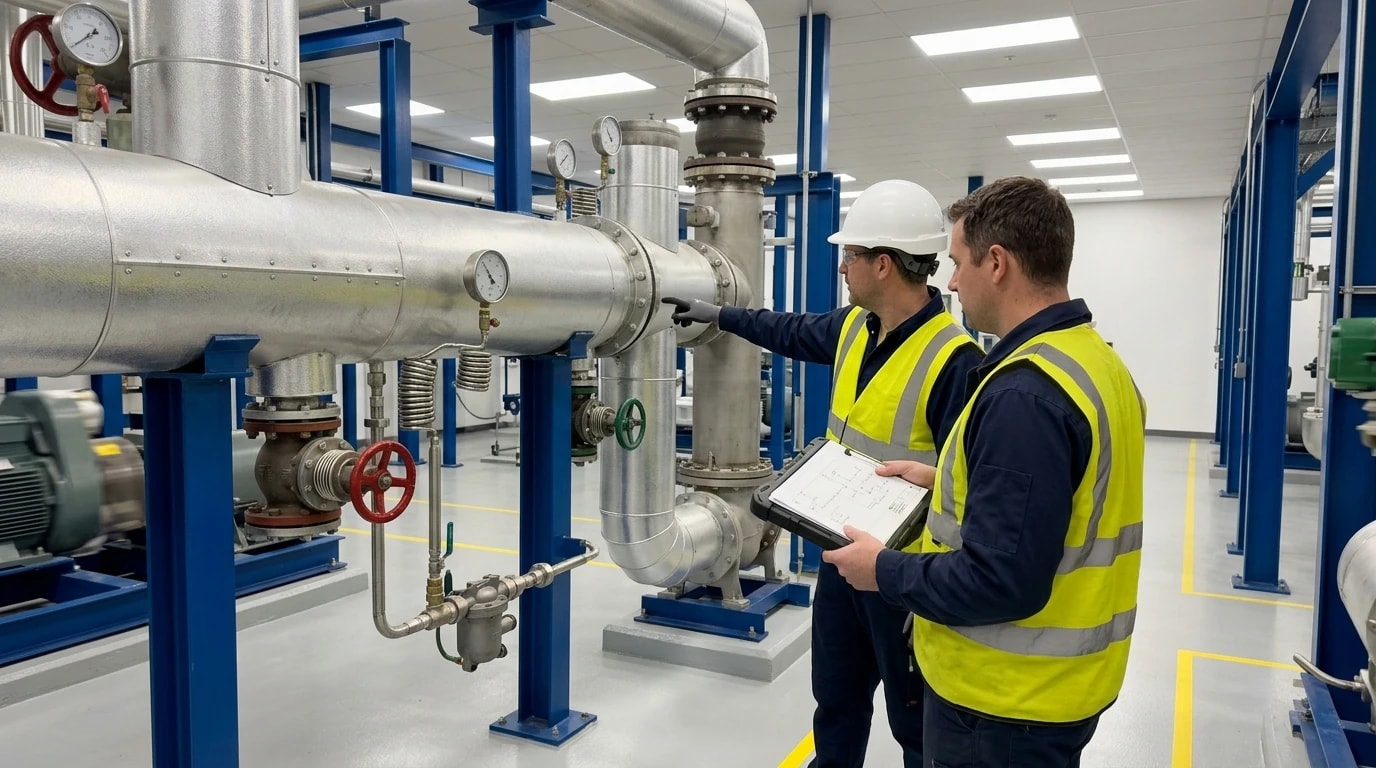
A thorough heat and mass balance reveals the specific mechanical and operational failures that degrade steam system efficiency.
| Major Source of Steam Waste | Typical Root Cause | Actionable Correction |
|---|---|---|
| High Flue Gas Stack Loss | Sub-optimal air-to-fuel ratios, soot build-up on boiler tubes | Real-time oxygen trim control, automated soot blowing |
| Atmospheric Flash Venting | Absence of flash steam recovery vessels, failed steam traps | Installing flash vessels, routine acoustic testing of traps |
| Condensate Discard | Cavitation fears, complex return line geometry, contamination | Re-engineering condensate return loops, installing oil separators |
| Convective Pipeline Losses | Damaged, wet, or entirely missing pipe insulation | Installing weather-proof insulation jackets on valves and flanges |
Quantifying Heat Losses and Flue Gas Stack Losses
Flue gas stack loss is the largest single source of energy waste in industrial boilers. If stack gases exit the chimney at temperatures exceeding 150 °C, substantial heat is escaping.
This waste is often caused by operating with too much excess air. While some excess oxygen is required to ensure complete combustion, too much air increases the volume of dry gas that carries sensible heat out of the stack. Conversely, operating with insufficient air leads to incomplete combustion, wasting fuel through the production of carbon monoxide and unburned carbon. An HMB calculation accurately correlates stack temperature and fuel chemistry, enabling engineers to optimise the burner's air-to-fuel ratio and install flue gas economisers to preheat incoming boiler feedwater.
Condensate Recovery and Flash Steam Losses
When high-pressure condensate passes through a steam trap into a lower-pressure condensate return main, its temperature instantly drops to the saturation temperature at that lower pressure. The excess energy vapourises a portion of the liquid, generating flash steam.
In many older process plants, this flash steam is vented directly to the atmosphere to prevent backpressure build-up in the condensate lines. However, venting flash steam represents a severe thermal loss; flash steam often contains 10% to 15% of the total energy of the original condensate. By constructing a mass and energy balance around the condensate return system, engineers can size a flash vessel to capture this low-pressure vapour and route it to low-temperature heating duties, such as preheating process feeds or boiler make-up water.
Insulation Deficiencies and Mechanical Malfunctions
Steam lines operating at high temperatures lose significant energy via radiation and convection if they are poorly insulated. For example, a single uninsulated pipe flange on a high-pressure steam line can lose heat equivalent to several metres of uninsulated pipe.
Mechanical failures in steam traps are another primary driver of energy loss. In unmonitored steam networks, 15% to 20% of steam traps frequently fail in the open position. This allows live, high-velocity steam to blow directly into the condensate return system. This increases backpressure, reduces the efficiency of upstream heat exchangers, and wastes valuable heat.

Map every energy and material flow in your process with detailed heat and mass balance calculations — the foundation for any optimisation or design project.
Process Simulation Software for Mass Balance and Pinch Analysis
Manual calculation of complex steam networks is incredibly time-consuming and prone to mathematical errors. Process design and energy management teams therefore rely on modern simulation software and thermodynamic techniques to model and optimise utility networks.
Aspen Plus, HYSYS, and DWSIM in Steam Cycle Modelling
Process engineers frequently utilise commercial simulation packages such as Aspen Plus and HYSYS, or open-source flowsheeting tools like DWSIM, to develop high-fidelity steady-state and dynamic models.
- Aspen Plus: Highly valued by industry professionals for chemical manufacturing, solids processing, and complex reactive distillation systems. It allows designers to model physical phase equilibria with advanced physical property databases.
- HYSYS: Widely used in the oil and gas, refining, and petrochemical industries. It excels at modelling vapour-liquid equilibrium (VLE) in complex hydrocarbon and utility steam systems.
- DWSIM: An open-source, CAPE-OPEN compliant chemical process simulator. It provides process engineers with a free, highly capable platform for simulating steady-state thermodynamic systems, including water and steam cycles using the IAPWS-97 steam tables.
These software tools allow engineers to input the exact composition, pressure, and temperature of every process stream, select appropriate thermodynamic equations of state (such as Peng-Robinson or NRTL), and simulate the performance of heat exchangers, boilers, and steam turbines.
Pinch Analysis for Energy Integration
First developed by Linnhoff March, pinch analysis is the industry-standard methodology for thermodynamic energy integration. Rather than evaluating individual heat exchangers in isolation, pinch analysis looks at the entire facility as an integrated system.
Process engineers list every hot stream (which must be cooled) and every cold stream (which must be heated) along with their respective mass flow rates, heat capacities, and target temperatures. The software then aggregates these streams to construct Hot and Cold Composite Curves. By plotting these curves on a Temperature-Enthalpy diagram, engineers identify the "Pinch Point". The pinch point represents the narrowest temperature difference (ΔTmin) between the hot and cold curves, dividing the process into two separate thermodynamic zones:
- Above the Pinch: A heat sink area that requires external heating utility (e.g., steam).
- Below the Pinch: A heat source area that requires external cooling utility (e.g., cooling water).
Heat Exchanger Network Optimisation
The golden rule of pinch analysis is simple: never transfer heat across the pinch point. Doing so creates a double penalty—it increases both the heating utility demand above the pinch and the cooling utility demand below the pinch.
By optimising the Heat Exchanger Network (HEN) based on pinch principles, process design teams can arrange preheat trains to recover energy from hot process effluents to preheat cold feed streams. This reduces steam utility demands by 10% to 40% without requiring modifications to the core chemistry of the plant.
The 11-Step Engineering Methodology for Thermal Optimisation
To standardise the transition from raw field data to validated, high-efficiency thermal designs, process engineers implement a structured, 11-step engineering methodology.
Phase 1: Raw Data Acquisition and Sensor Verification
- Step 1: Initial Data Acquisition: Thermal engineers collect historical operational logs, process flow diagrams, Piping and Instrumentation Diagrams (P&IDs), and electrical utility records.
- Step 2: Thermodynamic Boundary Definition: Strict physical and thermodynamic boundaries are drawn around individual unit operations to isolate energy flows.
- Step 3: Sensor Validation and Calibration: Engineers verify the calibration, accuracy, and physical position of field instrumentation to ensure the reliability of raw temperature, pressure, and flow measurements.
- Step 4: Species-Level Mass Balance Formulation: Mass conservation equations are written for all chemical species and physical phases (solid, liquid, vapour) crossing the defined process boundaries.
Phase 2: Steady-State Model Reconciliation and Thermodynamic Modelling
- Step 5: Enthalpy Balance and Energy Accounting: Total enthalpies are calculated for all entering and leaving streams, factoring in sensible heat, latent heat of phase change, and chemical heats of reaction.
- Step 6: Steady-State Simulation Construction: Thermal design teams construct a steady-state simulation of the steam and process system, utilising tools such as Aspen Plus, HYSYS, or DWSIM to execute stream calculations.
- Step 7: Model Calibration and Validation: Engineers fine-tune the simulation by matching its outputs to the validated physical measurements obtained in Step 3, ensuring the model matches real-world operation.
- Step 8: Dynamic Simulation (Optional): If the process operates in batches or experiences rapid thermal transients, engineers develop a dynamic model to track time-dependent heat transfer and fluid flow behaviours.
Phase 3: Sankey Energy Mapping and Process Flow Diagram Creation
- Step 9: Final Heat and Mass Balance Generation: The validated simulation compiles the final, closed HMB stream tables, containing exact chemical species flow rates, physical states, temperatures, pressures, enthalpies, and densities.
- Step 10: Sankey Energy Mapping and PFD Creation: Engineers generate a high-fidelity Process Flow Diagram (PFD) containing embedded stream tables and Sankey diagrams that visually map every energy input, useful work output, and thermal loss across the plant.
- Step 11: Actionable Efficiency Recommendations: The final HMB serves as a single source of truth to evaluate energy-saving projects. It provides the precise thermodynamic basis to calculate project paybacks, return on investment (ROI), and carbon emissions (CO₂e) reduction metrics.
Industrial Sector Applications and Case Studies
The thermodynamic discipline of heat and mass balance applies to many energy-intensive manufacturing sectors, with each industry facing its own unique technical and regulatory constraints.
Chemical Processing and Reactive Distillation
Chemical manufacturing plants consume large amounts of high-pressure steam, primarily in distillation column reboilers to separate chemical components. In reactive distillation systems, where chemical reactions and physical separations occur in a single column, thermal profiles are extremely complex.
Applying an HMB analysis allows chemical engineers to model these simultaneous reaction kinetics and multi-phase equilibria. By performing pinch analysis on a petrochemical preheat train, process engineers can identify where hot column product streams can preheat cold raw feeds, bypassing the steam reboiler entirely. In many chemical plants, this heat integration reduces reboiler steam demands by 15% to 25%, which debottlenecks the utility system and lowers operating costs.
Pharmaceutical Batch Reactors and GMP Standards
In pharmaceutical manufacturing, batch reactors must be heated and cooled rapidly to control reaction rates and ensure product quality. Because pharmaceuticals are produced under strict Good Manufacturing Practice (GMP) regulations, changing the physical process inside product-contact vessels is extremely restricted.
To bypass these regulatory hurdles, engineers use heat and mass balance models to focus entirely on the non-contact utility side of the process. For example, by modelling the steam and cooling water cycles, engineers can design a dynamic heat recovery system. This can include a vertical baffle plate buffer tank to store warm cooling-water discharge, which is then reused to preheat process wash water. This utility-side optimisation avoids altering the GMP-validated process while reducing overall plant steam consumption by up to 20%.
Food Manufacturing and Pulp Mill Dryer Efficiency
Food manufacturing processes, such as spray drying and multi-effect evaporation, must maintain strict sanitary and Hazard Analysis Critical Control Point (HACCP) standards. Similarly, pulp and paper mills require massive steam inputs, with the dryer section consuming up to 70% of the mill's steam.
Applying heat and mass balance modelling to a paper machine allows engineers to optimise the steam and condensate cascade system. High-pressure steam is used in the final drying cylinders, and the resulting flash steam and hot condensate are cascaded down to supply lower-pressure cylinders. In typical European pulp mills, executing an HMB-driven cascade optimisation reduces fresh steam consumption by 12% to 18.5%, providing a project payback period of less than 16 months.
This article reflects the independent analysis and editorial opinion of EnerTherm Engineering. Product names, trademarks, and brands mentioned belong to their respective owners. EnerTherm Engineering is not affiliated with, endorsed by, or a licensee of any third-party software or product mentioned unless explicitly stated.

Simulation Engineer — EnerTherm Engineering
Rajesh Sekar is a Simulation Engineer at EnerTherm Engineering, specialising in computational fluid dynamics (CFD), finite element analysis (FEA), and thermal process simulation. He holds a degree from Cranfield University and brings extensive experience in simulation-based product development from the automotive, aerospace, and energy sectors.
