How API Standard Refinery Modelling Stops PRV Oversizing
Validating transient pressure rises and non-ideal gas behaviour to API 521.
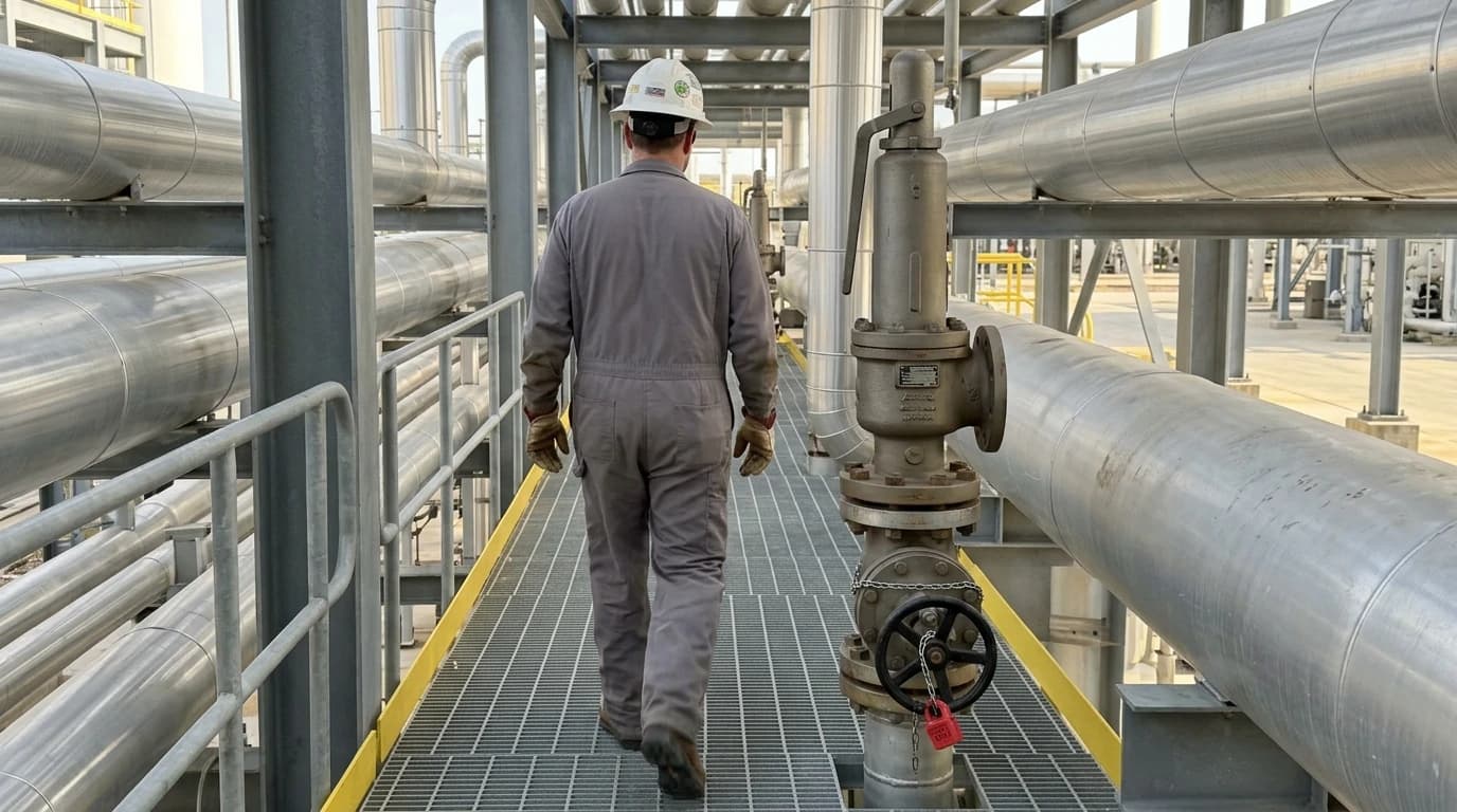
API standard refinery process modelling simulates fluid thermodynamics and pressure-relief scenarios in accordance with American Petroleum Institute (API) codes. In industrial hydrocarbon facilities, specifying oversized pressure-relief valves (PRVs) represents a severe operating risk that can lead to valve chatter, mechanical seat damage, and catastrophic loss of containment. Traditionally, static steady-state relief calculations have dominated engineering practices. However, these oversimplified models often overestimate required relief areas because they assume uniform, instantaneous peak thermal loads. By transitioning to dynamic simulation workflows, design engineers can precisely model the transient nature of overpressure events, ensuring compliance with safety regulations while preventing the high capital costs and hazards associated with oversized safety devices.

Map every energy and material flow in your process with detailed heat and mass balance calculations — the foundation for any optimisation or design project.
The Regulatory Mechanics of API Standard 521 and Sizing Standards
The Transition from Steady-State to Dynamic Validation
Process design teams historically relied on static heat-input equations to determine the relieving rates for safety valves. This practice assumes a constant heat transfer rate and an instantaneous, peak vapourisation rate across the entire vessel surface. However, real-world overpressure events are highly transient; system temperature, pressure, and fluid compositions change continuously.
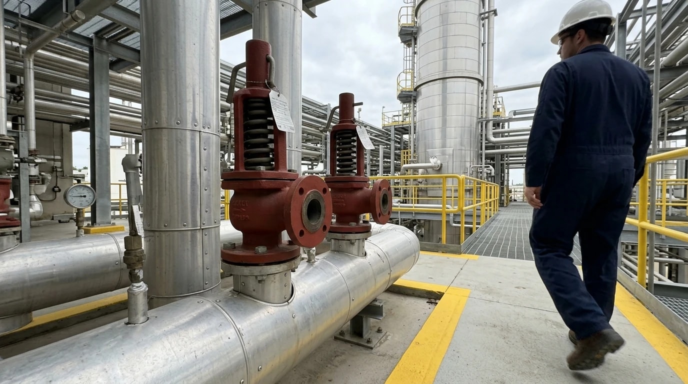
API Standard 521 (7th Edition, 2020) (Pressure-relieving and Depressurising Systems) provides the essential framework for dynamic simulation validation under Section 4.3.3. The standard explicitly states that dynamic simulation provides an alternative method to better define the relief load and improves the understanding of what happens during relief. By modelling the time-dependent behaviour of the system, engineers can track thermal and pressure profiles over time, showing that peak relief requirements are often significantly lower than steady-state estimates.
Integrating Sizing Standards: API 520, 521, and 537
Designing a safe, code-compliant relief network requires coordinating three distinct standards. First, API Standard 520 (Part I, 10th Edition, 2020 and Part II, 7th Edition, 2020) governs the sizing and selection of the pressure-relief valve itself, translating fluid properties at relief conditions into physical orifice dimensions. Second, API Standard 521 (7th Edition, 2020) covers the broader pressure-relieving and depressurising system, defining overpressure causes, calculating individual relief rates, and establishing disposal system design limits. Third, API Standard 537 (4th Edition, 2024) regulates the design and operation of flare gas recovery units and flare stack burners.
In the UK and Europe, these guidelines are integrated with BS EN ISO 23251:2020, which establishes identical requirements for pressure-relieving systems. Engineering teams must show strict compliance with these harmonised standards to pass regulatory audits conducted by the UK Health and Safety Executive (HSE) under the Control of Major Accident Hazards (COMAH) Regulations 2015.
Managing Regulatory Audits During FEED
During Front-End Engineering Design (FEED) regulatory audits, process safety managers must defend their selected safety valve orifices. Specifying an excessively oversized PRV can raise immediate audit flags. An oversized valve operates inefficiently; when it opens, the vessel pressure drops so rapidly that the valve immediately closes, only to reopen as pressure builds again. This cycling, known as chatter, can destroy the valve internals and result in massive, unmitigated chemical releases. By utilising API standard refinery process modelling, design teams can present audited proof of transient peak loads, validating that the chosen PRV sizes are perfectly suited to the process hazards.
Why Steady-State Methods Cause PRV Oversizing in Fire-Case Modelling
The Fallacy of the Peak Relief Assumption
The fire-case scenario is the most common design basis for refinery vessels. Steady-state calculations assume that a vessel exposed to a pool fire or jet fire receives a uniform, high-intensity heat flux across its entire wetted surface. For gas-filled vessels, standard static equations assume that peak vapour generation occurs when the gas reaches its maximum relieving temperature and the metal wall reaches its maximum design temperature, typically 595 °C for carbon steel.
This assumption is fundamentally flawed because it ignores the physical delay in heat transfer through the vessel shell. The peak internal pressure, peak gas temperature, and peak wall temperature do not occur simultaneously. Instead, they are distributed over a transient timeline that steady-state equations cannot resolve.
Thermal Wall Degradation vs. Transient Pressure Rise
For gas-filled vessels under thermal stress, the mechanical strength of the steel wall degrades rapidly as temperature rises. Because gas has a very low thermal conductivity and heat capacity compared to liquids, the vessel wall heats up much faster than the gas inside.
Dynamic simulation studies reveal that the vessel wall will typically reach its rupture stress temperature and fail mechanically before the internal pressure rises enough to open an oversized PRV. Sizing a massive PRV based on steady-state peak gas temperatures does not protect the vessel from thermal failure; instead, it installs a valve that may never open fully, while introducing the risk of destructive seat chatter. Dynamic simulation shows that steady-state methods can oversize relief valves by a factor of 1.27 to 6.50, with a mean oversizing factor of 2.35 for gas-filled vessels exposed to fire.
The Fire-Case Heat Absorption Formula
To calculate the heat input from an external fire, API Standard 521 (7th Edition, 2020) uses the empirical relationship:
Q=C⋅F⋅Aw0.82Where:
- Q is the total heat absorption rate expressed in BTU/hr (or Watts in SI units),
- C is the heat absorption constant, which equals 21,000 for US customary calculations (or 43,200 for metric SI calculations),
- F is the environmental factor, which accounts for external insulation and drainage (ranging from 1.0 for bare steel to 0.075 for systems with certified fireproofing),
- Aw is the wetted surface area of the vessel in square feet (or square metres).
Static calculations apply this heat input Q directly to vapourise liquid or expand gas, assuming zero heat is absorbed by the steel mass. Dynamic simulations, by contrast, solve the coupled heat transfer equations, allocating a significant portion of Q to heating the metal wall itself, which drastically reduces the calculated peak relief rate and prevents oversizing.

Map every energy and material flow in your process with detailed heat and mass balance calculations — the foundation for any optimisation or design project.
Implementing API Standard Refinery Process Modelling in Engineering Workflows
EnerTherm's 11-Step Methodology for High-Fidelity Simulation
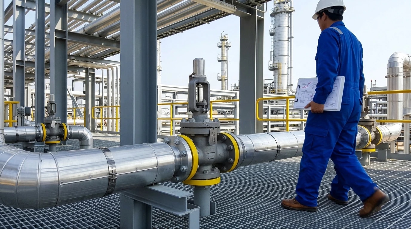
EnerTherm Engineering utilises a structured 11-step engineering methodology to standardise heat and mass balance (HMB) simulations. This methodology provides a single source of truth for refinery design, starting with initial project definition and extending to dynamic safety validation.
First, the design team defines the scope and gathers operational data, including P&IDs, historical operating logs, and site-specific constraints. Next, engineers develop crude assay pseudo-component slates based on True Boiling Point (TBP) curves to accurately capture the distillation behaviour of heavy hydrocarbon fractions.
The middle steps focus on establishing steady-state models, selecting appropriate thermodynamic equations of state, and identifying all credible overpressure scenarios. The workflow then transitions to dynamic safety validation under API Standard 521 (7th Edition, 2020) Section 4.3.3, which allows engineers to calculate transient pressure rises and non-ideal gas behaviour.
Software Tools and Thermodynamic Alignment
To execute these rigorous calculations, simulation engineers select platforms such as Aspen Plus, Aspen HYSYS, Honeywell UniSim, or DWSIM. These tools feature advanced flash algorithms that can model non-ideal gas behaviour and compressibility changes near critical temperatures.
When modelling depressurisation or fire cases, the software tracks thermodynamic parameters at every time-step, resolving the Joule-Thomson cooling or heating effect as high-pressure gas expands across relief valves. This thermodynamic alignment ensures that the calculated relief rates are highly accurate and fully compliant with API Standard 520 and API Standard 521.
Crude Assay and Pseudo-Component Integration
Hydrocarbon fluids in refineries are multi-component mixtures with boiling points spanning hundreds of degrees. Sizing a relief valve for these streams requires characterising the heavy fractions using pseudo-components. If the thermodynamic model does not accurately represent the light, volatile components within the heavy crude, the calculated bubble point of the mixture will be incorrect. This error will cause the simulation to over-predict the initial vapourisation rate under fire exposure, resulting in an oversized PRV. Accurate pseudo-component slate development is therefore essential for high-fidelity safety simulations.
Flare Header Design and Sizing to Prevent Condensation Hazards
API 521 Flare Header Slope Requirements
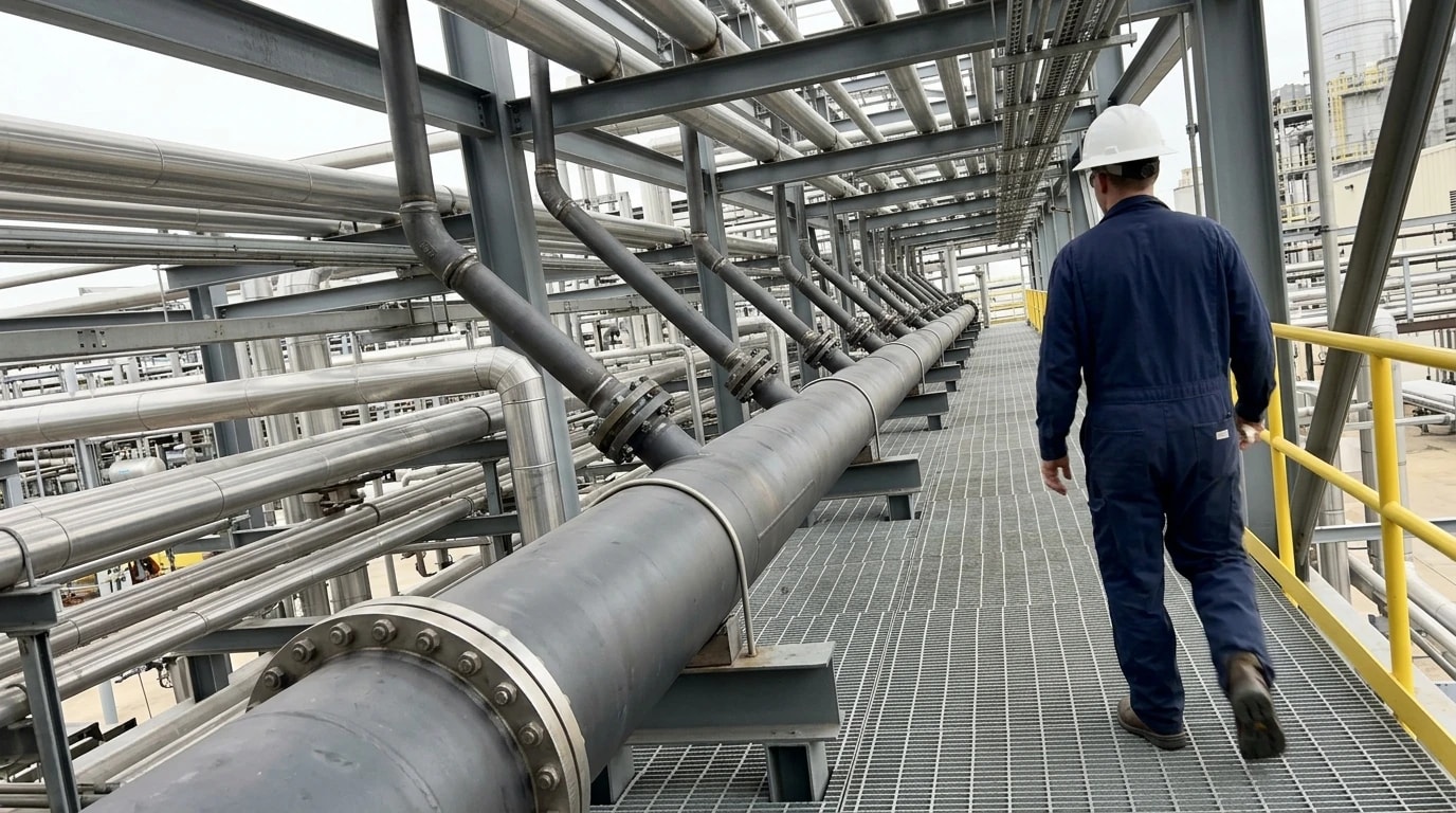
Once the PRV sizes are optimised, the relief streams must route safely to the disposal system. The layout of the discharge piping is governed by strict physical requirements. API Standard 521 (7th Edition, 2020), Section 5.4.1.3.7(c) specifies that horizontal flare headers must have a minimum slope of 1/4 inch per 10 feet, which represents a 0.208% gradient. This gradient ensures that any heavy hydrocarbons that condense in the header drain continuously to the flare knockout drum.
Preventing Slugging and Water Hammer
Insufficient slope or pipe sag between supports allows liquid pockets to accumulate in the header. During a major relief event, high-velocity vapour flows can sweep these liquid pockets into massive liquid slugs. Traveling at high speeds, these slugs can cause severe structural vibration, pipe fatigue, and water hammer, which can lead to catastrophic piping failure. Sizing headers and checking support deflections are critical steps during the FEED phase to guarantee that the main headers remain clear of liquid inventory.
Pipe Sag and Deflection Calculations
Process piping design teams must calculate the worst-case deflection between structural supports to ensure that the pipe does not sag below the draining elevation. The table below outlines the cumulative elevation drop required for different slope conventions over various run lengths:
| Header Run Length | 1/4 inch per 10 feet (0.208% Gradient) | 1/32 inch per foot (0.26% Gradient) | 1/8 inch per foot (1.04% Gradient) |
|---|---|---|---|
| 500 feet (152.4 metres) | 12.5 inches (318 mm) | 15.6 inches (396 mm) | 62.5 inches (1,588 mm) |
| 1,000 feet (304.8 metres) | 25.0 inches (635 mm) | 31.3 inches (795 mm) | 125.0 inches (3,175 mm) |
| 2,400 feet (731.5 metres) | 60.0 inches (1,524 mm) | 75.0 inches (1,905 mm) | 300.0 inches (7,620 mm) |
Selecting the minimum API 521 slope of 0.208% minimises the physical drop of the pipe, allowing the knockout drum inlet nozzle to be positioned at a lower, more cost-effective elevation. However, it requires a higher density of pipe supports to prevent sag-induced pocketing.
FEED Siting and Design Optimisation via Thermal Radiation Contours
Mapping Radiation Fields with API 521 Table 5
During safety audits, regulatory compliance officers scrutinise the safety of the flare stack location. API Standard 521 (7th Edition, 2020) Table 5 establishes the permissible thermal radiation levels for different exposure scenarios. These thresholds protect personnel and structures from intense thermal energy released during flaring.
Continuous exposure for personnel wearing standard work clothing is restricted to 1.58 kW/m² (500 BTU/hr·ft²). For equipment and structural steel, the allowable radiation rises to 6.31 kW/m² (2,000 BTU/hr·ft²).
Sizing the Flare Stack Height for the 1,500 BTU/hr·ft² Boundary
The most critical design boundary for personnel safety is the 4.73 kW/m² (1,500 BTU/hr·ft²) thermal radiation contour. API Standard 521 (7th Edition, 2020) specifies this as the maximum radiant heat intensity allowed in areas where emergency actions lasting two to three minutes can be required by personnel without shielding.
To secure regulatory approval during FEED audits, engineers must show that this 1,500 BTU/hr·ft² boundary does not intersect any occupied platforms or ground-level work areas. If the calculated relief load is oversized due to steady-state assumptions, the resulting flare radiation contour will be artificially large. This forces the design team to specify an excessively tall and expensive flare stack to meet safety codes.
By using high-fidelity API standard refinery process modelling, engineers can accurately predict the transient peak relief loads, lowering the heat release rate and optimising the flare stack height without compromising safety. This reduces structural costs and keeps the refinery footprint compact and efficient.
This article reflects the independent analysis and editorial opinion of EnerTherm Engineering. Product names, trademarks, and brands mentioned belong to their respective owners. EnerTherm Engineering is not affiliated with, endorsed by, or a licensee of any third-party software or product mentioned unless explicitly stated.

Managing Director — EnerTherm Engineering
Dr. François Pierrel is Managing Director of EnerTherm Engineering with over two decades of expertise in thermal design, heat transfer, and industrial energy optimisation. He holds a PhD in Heat Transfer from Cranfield University and a Post-Doctorate from Heriot-Watt University.
