Energy Analysis for Oil Refineries: An 8% Retrofit Case
A crude preheat train retrofit achieved 8% total energy savings after HEN rearrangement.
Energy analysis for oil refineries uses enthalpy balances, pinch analysis and utility mapping to reduce external fuel and utility demand while maintaining safe, stable operation and product specification.
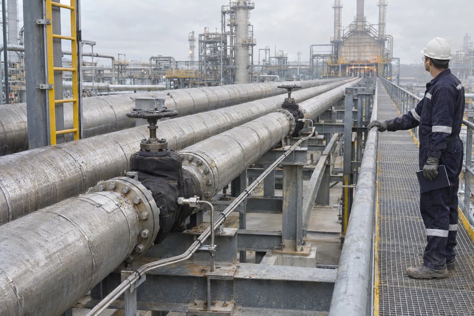
A crude distillation unit can carry 30 to 100 MW of fired-heater duty. At that scale, a few degrees lost across a crude preheat train can translate into substantial fuel-gas use, higher stack emissions and poorer unit energy intensity.
A 2021 crude-unit retrofit case documented by Ipieca achieved 8% total energy savings against its base case. The project combined detailed process simulation, data extraction, heat-exchanger-network analysis, exchanger rearrangement and an economic payback screen. It recovered more value from heat already circulating through the refinery.
Energy analysis converts historian data, P&IDs, crude assays and operating knowledge into a reconciled model of where heat enters, moves through and leaves the process. The result is a retrofit case tested against fouling, control, pressure drop, safety and turnaround constraints before capital is committed.
Why energy analysis for oil refineries begins with enthalpy balances
Heat duty follows the stream, not the equipment tag
A refinery is a connected thermal system. The crude distillation unit, vacuum unit, FCC unit, steam headers, fuel-gas system, furnaces and cooling network exchange energy across unit boundaries. An energy study that considers a fired heater alone may overlook the process conditions that determine its duty.
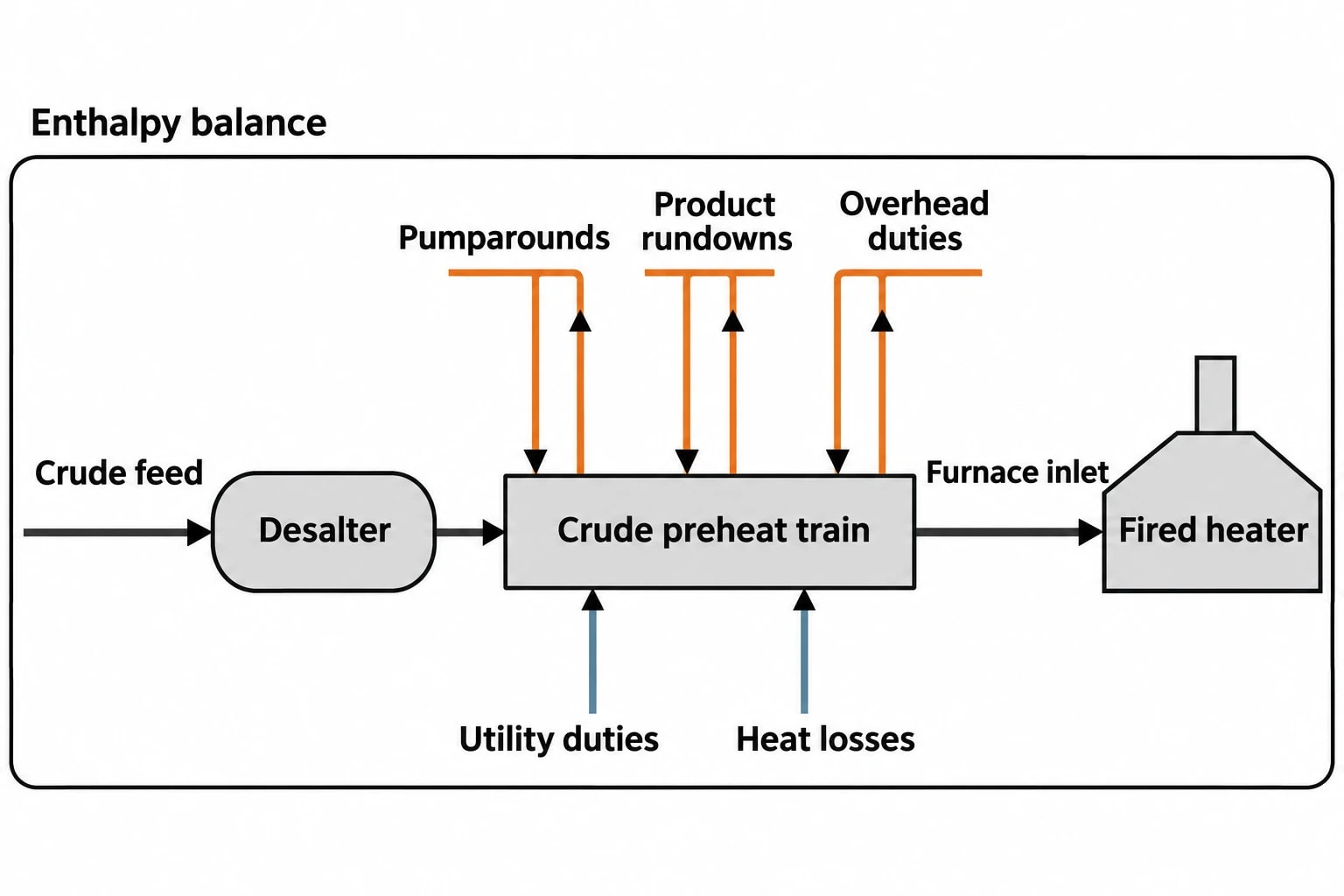
The starting point is an enthalpy balance for the operating case. Engineers define the mass flow, composition, pressure, supply temperature and target temperature for each relevant stream. The model then accounts for sensible heat, phase change where applicable, utility duties, fired duty and identified heat losses.
For a crude preheat train, the balance typically covers crude feed, desalter conditions, pumparounds, side-product rundowns, overhead duties and furnace inlet conditions. It should also establish which streams are available for heat recovery at the required operating conditions.
Similar furnace fuel rates can have very different causes. Crude may arrive at the furnace colder because exchangers are fouled. A changed crude slate may alter heat capacity and vapourisation behaviour. A bypass may be open. A higher coil-outlet-temperature target may reflect a downstream separation constraint. The enthalpy balance separates these causes.
A reconciled model provides the baseline
Raw plant data is valuable, though it is rarely ready for direct design use. Temperature tags can drift. Flow meters may not close a mass balance. Product rundown temperatures can change with storage requirements. Exchanger duty calculations can be distorted by bypass leakage, unstable operation or an uncertain crude assay.
A usable baseline requires a representative operating window and a clear data hierarchy. The following inputs normally need review:
- Crude rate, density and assay basis
- Stream temperatures, pressures and phase condition
- Pumparound and product-rundown flow rates
- Furnace fuel-gas rate, composition, stack oxygen and stack temperature
- Steam imports, exports and condensate returns
- Cooling-water and air-cooler loads
- Exchanger pressure drops, bypass positions and cleaning history
- Production rate, product specification and crude flexibility constraints
The goal is not a spreadsheet that closes by accident. It is a defensible operating model that explains observed utility consumption. Process teams can then distinguish a data-quality issue from a real heat-recovery shortfall.
EnerTherm Engineering’s 11-step heat and mass balance methodology applies this sequence from initial scope definition and data collection through steady-state modelling, option selection and FEED-ready documentation. The final process flow diagram and stream table provide a single source of truth for process, operations and project teams.

Map every energy and material flow in your process with detailed heat and mass balance calculations — the foundation for any optimisation or design project.
Crude preheat trains create the strongest retrofit opportunities
Why the preheat train matters
The crude preheat train transfers heat from hot product streams and pumparounds to cold crude before it enters the fired heater. Its performance directly affects the fuel required to achieve furnace coil-outlet temperature.
These networks are complex. Several exchangers sit in series, streams operate over different temperature ranges, and each match changes the driving force available to the next exchanger. A modification that improves one exchanger can reduce recovery elsewhere in the train.
Ipieca identifies crude-unit preheat trains and FCC units as high-value pinch-analysis applications because of their complex heat-exchanger networks and significant duty requirements. The 2021 case study in its compendium followed a retrofit sequence:
- Build a detailed process simulation.
- Extract process-stream and exchanger-network data.
- Set energy targets through pinch analysis.
- Develop practical retrofit options.
- Screen exchanger rearrangements against energy savings and acceptable payback.
The selected rearrangement delivered the documented 8% total energy saving. It is a case result, not a generic design allowance for other refineries.
Questions that determine whether a retrofit is practical
A crude preheat retrofit needs more than an attractive heat-duty calculation. The proposed network must operate across crude changes, rate changes and normal control interventions.
| Retrofit question | Engineering consequence |
|---|---|
| Can the hot stream heat crude at a more useful temperature level? | Improved temperature placement can reduce fired-heater duty. |
| Does the current sequence create cross-pinch heat transfer? | Cross-pinch transfer raises hot and cold utility demand above the target. |
| Is sufficient exchanger area available at the proposed temperature approach? | The duty may require additional surface area or a new exchanger. |
| Will the new match increase fouling exposure? | Fouling can erode heat recovery and raise pressure drop. |
| Can control valves and bypasses maintain stable operation? | An operable network must tolerate normal rate and crude changes. |
| Can piping and tie-ins be installed within the turnaround scope? | Layout, isolation and access shape the brownfield cost and schedule. |
The best answer may be a revised exchanger sequence, targeted cleaning, a new exchanger, altered bypass philosophy or a package of smaller changes. Each should be compared with the same reconciled baseline.
Pinch analysis sets the thermodynamic target
What the pinch point shows
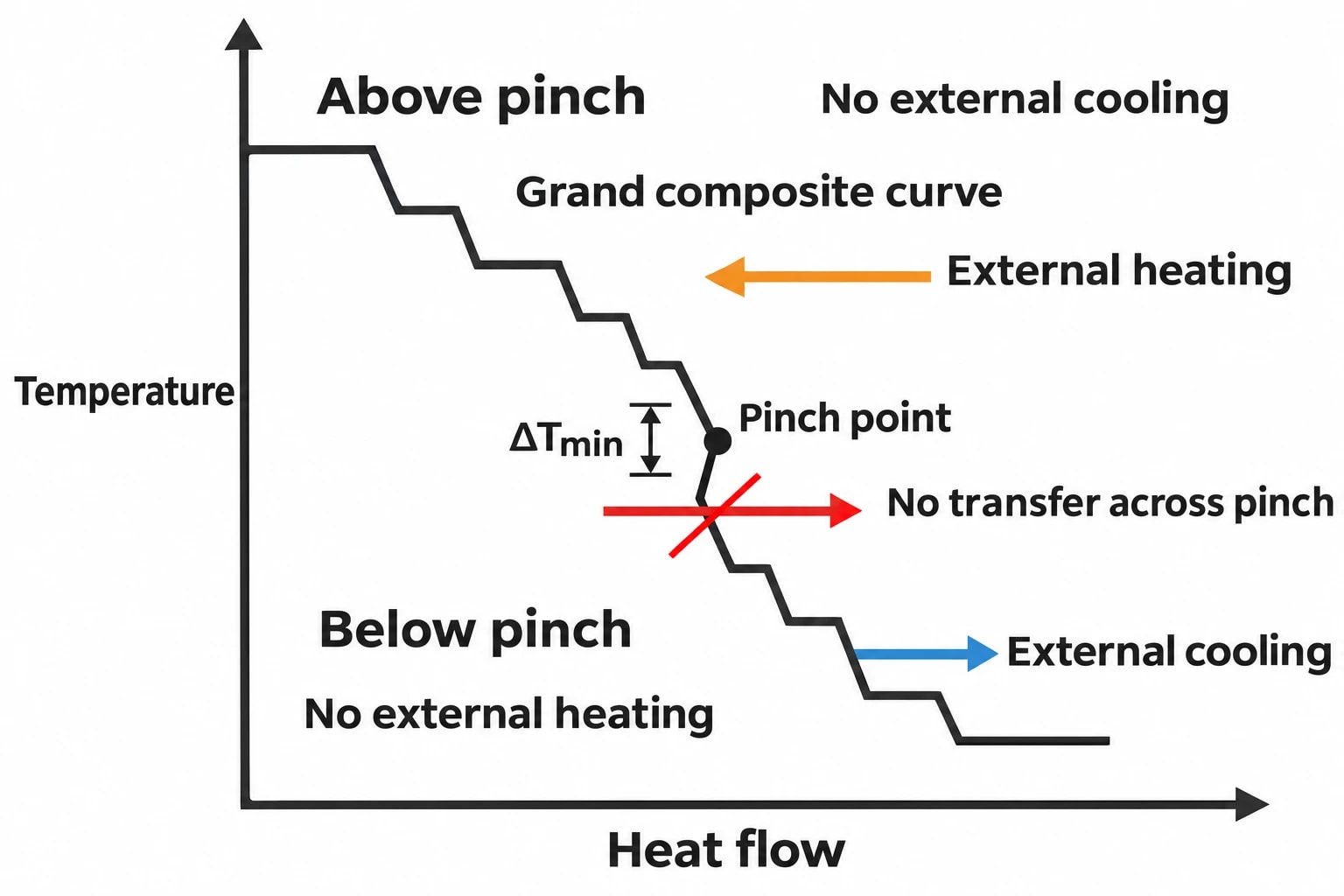
Pinch analysis identifies the minimum external heating and cooling demand of a process at a selected minimum temperature approach, ΔTmin. It shows whether a proposed network sits close to the heat-recovery limit or leaves significant utility demand unaddressed.
Composite curves plot the heat released by hot streams and the heat required by cold streams across temperature. The grand composite curve shows utility demand by temperature level. Together, they reveal where process heat can be recovered and where external utility remains necessary.
The pinch point occurs where the selected minimum temperature approach is reached. It divides the system into two regions. The design rules are precise:
- Do not add external cooling above the pinch.
- Do not add external heating below the pinch.
- Do not transfer heat across the pinch.
Breaking any of these rules increases demand for both hot and cold utilities above the thermodynamic minimum. In a refinery, that can mean greater fired-heater fuel demand and increased cooling-water or air-cooler duty.
ΔTmin is an economic and operability choice
A lower ΔTmin can increase the theoretical heat-recovery target. It can also require more exchanger area, tighter temperature approaches, more complex control and greater sensitivity to fouling. A higher ΔTmin reduces capital demand but leaves more fired and cooling utility in the balance.
The appropriate value depends on fluid properties, exchanger type, fouling rate, pressure-drop limits, plot space, utility costs and available shutdown windows. Brownfield work often selects a target above the theoretical maximum recovery because the project must be constructible and operable.
Pinch analysis guides the design. It does not replace process engineering judgement. Engineers need to test start-up, shutdown, turndown, crude switching, exchanger isolation and failure positions for critical bypass valves.

Map every energy and material flow in your process with detailed heat and mass balance calculations — the foundation for any optimisation or design project.
Utility mapping connects heat recovery to refinery-wide fuel use
Map heat sources, sinks and utility grades
Utility mapping places the heat-exchanger network within the wider refinery energy system. It identifies where a utility compensates for poor process integration and where a unit-level saving could move a burden elsewhere.
For a crude unit, the map should include refinery fuel gas, fired heaters, steam headers, cooling water, air coolers, pumparounds and product-rundown duties. It should show both duty and temperature grade. A low-temperature heat source may contain substantial energy but have limited value for heating a stream close to furnace inlet temperature.
A practical utility map tracks:
- Fuel-gas flow, composition and pressure to the fired heater
- Heater fuel rate, duty, excess oxygen and stack temperature
- Crude temperature at the furnace inlet
- Pumparound and product-rundown duties
- Steam production, import, export and condensate return
- Cooling-water and air-cooler loads
- Major rejected-heat streams and their temperature range
This view prevents double counting. A reduction in crude-unit fired duty may release refinery fuel gas for another consumer, reduce supplementary fuel purchase, alter steam generation or change the loading of a shared utility system. The project case should record the marginal energy source and associated carbon dioxide consequence at refinery level.
Fired-heater data belongs in the energy balance
Process heat recovery and combustion performance are separate opportunities, but the energy analysis needs both. A well-integrated preheat train cannot compensate for unstable fuel-gas pressure, excessive air, poor pass balance or elevated stack temperature.
Fired-heater mapping should examine air-to-fuel control, oxygen readings, fuel composition, coil pressure drop, tube-skin-temperature margin and stack conditions. The analysis separates recoverable process heat from combustion losses, producing clearer savings estimates and operating indicators.
Commission Implementing Decision 2014/738/EU identifies pinch analysis, heat integration, heat and power recovery, controlled combustion, steam-system management and energy benchmarking within BAT 2 for mineral-oil and gas refining. The decision links refinery energy work to environmental performance rather than treating it solely as a fuel-cost exercise.
Turning an energy target into a plant change
Retrofit decisions need operating constraints
A pinch target can identify the direction of travel, but exchanger modifications must survive refinery operation. Exchanger rearrangement can affect hydraulic balance, corrosion risk, fouling tendency, controllability, relief cases and maintenance access.
Project teams should bring operations, inspection, process safety, mechanical engineering and maintenance into option screening. That avoids a concept that performs well in simulation yet requires impractical piping, unsuitable metallurgy or unacceptable isolation arrangements.
Economic screening should include installed cost, civil work, piping, valves, instrumentation, control changes, exchanger cleaning, inspection needs, outage duration and lost-production exposure. Fuel savings should use a stated baseline and defined operating cases.
Verification protects the business case
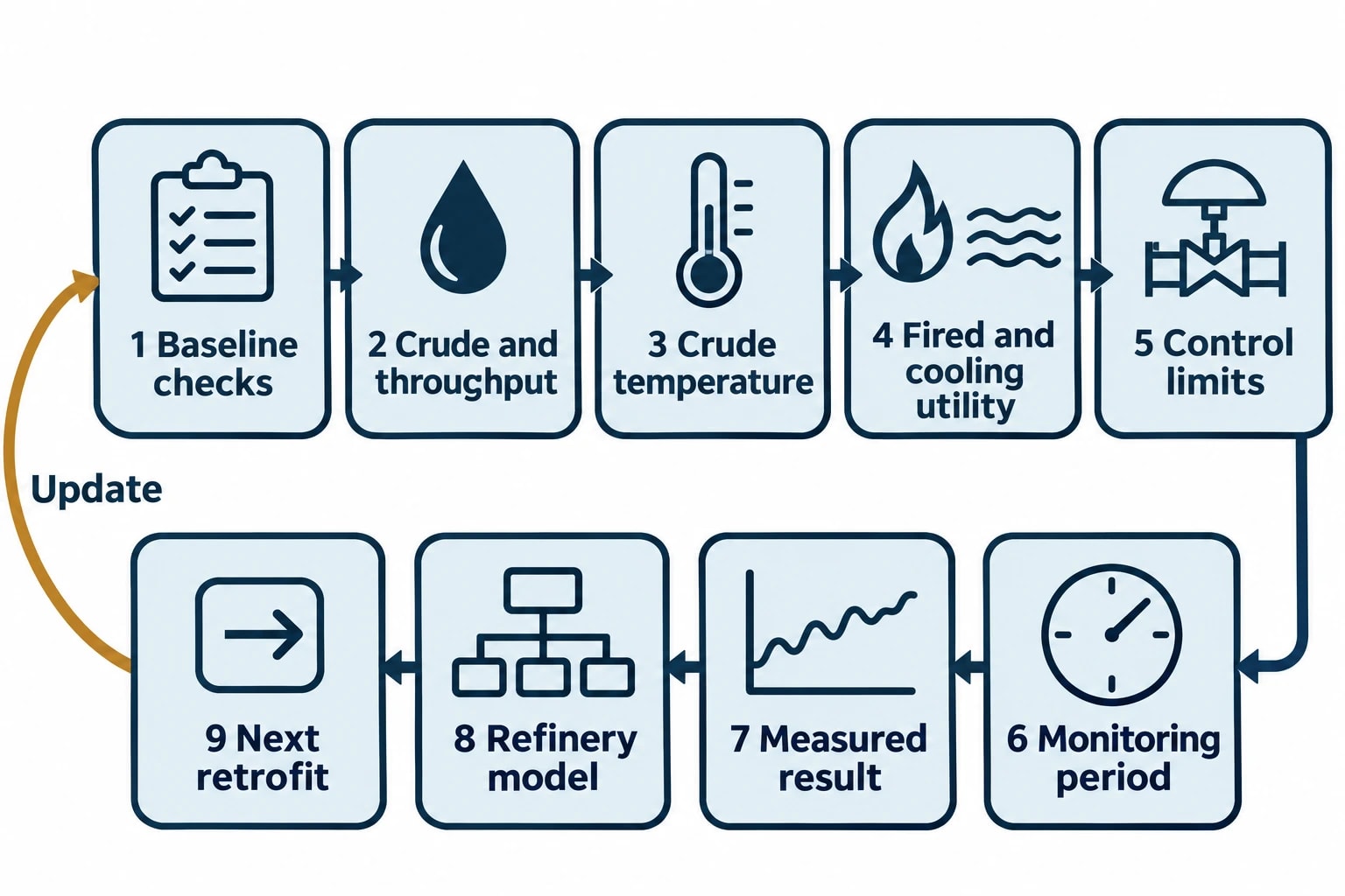
Post-project verification should use the same boundary and calculation method used in the investment case. Comparing fuel consumption without correcting for throughput, crude slate, ambient conditions and coil-outlet-temperature targets can misrepresent performance.
A sound verification plan records:
- The pre-project operating baseline and data-quality checks.
- The selected crude and throughput cases.
- The expected change in crude temperature to the furnace.
- The expected reduction in fired and cooling utility.
- The control and operating limits for the revised network.
- The monitoring period after commissioning.
The measured result should feed back into the refinery model. That allows engineers to update exchanger performance, identify fouling effects and assess the next retrofit option against a better baseline.
UK permitting context for refinery energy projects
BAT evidence supports permit decisions
GOV.UK states that installations such as refineries need to use best available techniques, and environmental permit conditions may specify BAT requirements or environmental outcomes based on BAT. Permit applications require operators to explain how applicable BAT will be followed, or justify an alternative technique that provides equivalent environmental protection.
For pre-2020 EU BAT conclusions relevant to Great Britain, Commission Implementing Decision 2014/738/EU remains important refinery guidance and evidence. Its energy-efficiency provisions support a structured approach to heat integration, combustion control and utility management.
A refinery retrofit file should retain the baseline heat and mass balance, stream data, pinch targets, option-screening criteria, forecast utility change and emissions assessment. This creates a traceable record for internal approval, permit engagement and subsequent verification.
This article reflects the independent analysis and editorial opinion of EnerTherm Engineering. Product names, trademarks, and brands mentioned belong to their respective owners. EnerTherm Engineering is not affiliated with, endorsed by, or a licensee of any third-party software or product mentioned unless explicitly stated.

Managing Director — EnerTherm Engineering
Dr. François Pierrel is Managing Director of EnerTherm Engineering with over two decades of expertise in thermal design, heat transfer, and industrial energy optimisation. He holds a PhD in Heat Transfer from Cranfield University and a Post-Doctorate from Heriot-Watt University.
