Pinch Analysis Cuts Power Plant Waste Heat by 10-40%
Design heat exchanger networks using composite curves to meet EU EED III 1 MW mandates.
Industrial power plants and heavy cogeneration facilities reject massive quantities of thermal energy to the atmosphere, often accounting for more than 50 per cent of their total fuel energy input. Pinch analysis for power plant waste heat recovery is a systematic thermodynamic methodology used to design and optimise heat exchanger networks (HEN) by establishing strict energy targets, identifying thermodynamic bottlenecks, and ensuring maximum process-to-process heat integration. By treating the entire thermal system as an interconnected network rather than a collection of isolated unit operations, this approach allows utility operators to systematically bridge the gap between theoretical thermodynamic limits and actual operating performance. In practical industrial retrofits, applying these thermodynamic principles reduces fuel consumption and waste heat dissipation by 10 to 40 per cent.
The Thermodynamics of Pinch Analysis in Power Generation
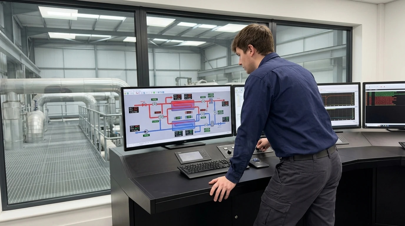
To understand how pinch analysis optimises a power plant, thermal design engineers must evaluate the system using the first and second laws of thermodynamics. Rather than designing individual heat exchangers in isolation, pinch analysis aggregates all hot streams (streams that require cooling) and all cold streams (streams that require heating) across the entire facility into two distinct curves.
Composite Curves and the Pinch Point
Plotting the cumulative heat capacity flow rate against temperature yields the Hot Composite Curve and the Cold Composite Curve. By shifting these curves horizontally along the enthalpy axis on a Temperature-Enthalpy (T−H) diagram, engineers can define the closest point of approach between them. This point represents the minimum temperature difference, designated as the Heat Recovery Approximation Temperature (HRAT) or ΔTmin.
The specific temperature level at which this minimum temperature difference occurs is defined as the thermodynamic pinch point. The pinch point acts as a thermodynamic barrier, dividing the entire process into two distinct thermal regions:
- Above the Pinch: A region of heat deficit that requires the import of external hot utility (such as steam or hot utility oil) but requires no external cooling.
- Below the Pinch: A region of heat surplus that requires the export of heat to an external cold utility (such as cooling tower water or air coolers) but requires no external heating.
The Three Golden Rules of Pinch Analysis
The fundamental operating principles of pinch analysis dictate three rigid rules that thermal design engineers must follow to achieve the minimum utility targets:
- No heat must be transferred across the pinch boundary.
- No external hot utility must be applied below the pinch.
- No external cold utility must be applied above the pinch.
To illustrate the consequences of violating these rules, the overall heat balance around the pinch boundary can be represented mathematically. When a quantity of heat (Qp) is transferred across the pinch from the hot region to the cold region, it creates a double penalty on the utility systems. The actual utilities required relate to the minimum thermodynamic targets through the following relationships:
QH,actual=QH,min+Qp QC,actual=QC,min+QpWhere:
- QH,actual is the actual hot utility required by the plant (MW)
- QH,min is the minimum thermodynamic hot utility target (MW)
- QC,actual is the actual cold utility required by the plant (MW)
- QC,min is the minimum thermodynamic cold utility target (MW)
- Qp is the quantity of heat transferred across the pinch boundary (MW)
Every megawatt of heat that crosses the pinch boundary (Qp) increases the high-temperature fuel demand by exactly one megawatt while simultaneously increasing the cooling water heat rejection load by one megawatt. Eliminating these cross-pinch heat transfers is the primary mechanism by which pinch analysis reduces power plant fuel use and waste heat dissipation.

Pinch analysis identifies the thermodynamic minimum energy requirement of your process — then designs the heat exchanger network to achieve it.
Regulatory Mandates: EU EED III and Mandatory Waste Heat Recovery
Industrial facilities and utility-scale power plants operate within increasingly strict regulatory frameworks. The transition from voluntary heat integration to mandatory performance standards has placed thermodynamic optimisation at the centre of regulatory compliance.
Directive (EU) 2023/1791 (EED III)
The recast of the European Union Energy Efficiency Directive, formally designated as Directive (EU) 2023/1791 (EED III), entered into force in late 2023, with Member States required to transpose its core provisions into national legislation by 11 October 2025. EED III establishes a legally binding target to reduce final energy consumption across the EU by 11.7 per cent by 2030 compared to 2020 projections.
Under Article 26 of EED III, the supply of heating and cooling is subject to rigid efficiency requirements, transforming waste heat recovery into a legal obligation for many operators. The directive introduces specific, scale-dependent thresholds:
| Facility Type & Scale | Regulatory Obligation under EED III | Technical Assessment Requirement |
|---|---|---|
| Data centres and thermal facilities with a total rated energy input exceeding 1 MW | Mandatory waste heat utilisation unless proven technically or economically unfeasible. | Perform a detailed Cost-Benefit Analysis (CBA) addressing technical feasibility, cost-efficiency, and local heat demand. |
| Combustion installations and energy production facilities with a total rated thermal input exceeding 20 MW | Mandatory assessment of using waste heat to satisfy economically justified demand. | Evaluate connection to a district heating network or integration into a high-efficiency cogeneration scheme. |
JRC Guidelines and Validation Standards
The European Commission's Joint Research Centre (JRC) publishes reference guidelines that define and account for waste heat. JRC guidelines recognise pinch analysis as the gold standard methodology to mathematically prove that a power generation or industrial facility has exhausted all internal heat recovery opportunities before exporting excess thermal energy off-site.
If a power plant operator intends to claim subsidies for district heating injection, or if a data centre operator seeks to prove that heat recovery is technically unfeasible under Article 26, the facility must undergo a rigorous process integration study. The pinch analysis serves as the formal engineering audit that defines the thermodynamic limits of the site, establishing whether the waste heat is of sufficient thermal grade to be integrated internally or if it represents a genuine surplus available for external regional grids.
Step-by-Step Methodology: Mapping the Power Plant HEN
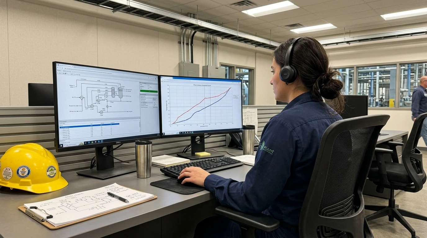
A structured pinch analysis project requires a systematic progression from raw plant instrumentation data to a fully optimised heat exchanger network. Process engineers follow a defined multi-step workflow.
Step 1: Stream Identification and Data Extraction
The analysis begins with a comprehensive mass and energy balance of the power plant. Thermal design engineers must extract the following parameters for every process stream that undergoes heating or cooling:
- Supply Temperature (Ts): The initial temperature of the stream as it enters the network (°C).
- Target Temperature (Tt): The final desired temperature of the stream for subsequent process stages (°C).
- Heat Capacity Flow Rate (CP): The product of the mass flow rate (m˙) and the specific heat capacity (Cp), measured in kW/K:
In utility-scale power plants, critical streams include boiler feedwater, flue gas streams, combustion air preheaters, turbine extraction steam, condenser cooling water, and blowdown streams.
Step 2: Selecting the Optimum HRAT / ΔTmin
The selection of ΔTmin represents a fundamental economic trade-off. A smaller temperature approach increases process-to-process heat recovery, lowering utility costs. However, because the driving force for heat transfer is reduced, the required surface area (A) of the heat exchangers increases exponentially according to the fundamental heat transfer relation:
A=U⋅ΔTlmQWhere Q is the heat duty (kW), U is the overall heat transfer coefficient (kW/m2K), and ΔTlm is the logarithmic mean temperature difference (K).
Thermal design teams typically balance these capital costs (CAPEX) against operating energy savings (OPEX) to determine the optimum ΔTmin. In power plants, typical optimum values vary based on fluid phases:
- Gas-to-Gas streams (e.g., Flue Gas to Air Preheaters): 20 °C to 30 °C due to low heat transfer coefficients.
- Liquid-to-Liquid streams (e.g., Feedwater Preheaters): 10 °C to 15 °C.
- Condensing/Boiling streams (e.g., Steam Condensers): 5 °C to 10 °C.
Step 3: Constructing Composite Curves and Grand Composite Curves
Once the stream data and ΔTmin are established, the hot and cold streams are combined into composite curves. The curves are shifted vertically by subtracting ΔTmin/2 from the hot stream temperatures and adding ΔTmin/2 to the cold stream temperatures. This shifting ensures that the two curves touch at the pinch point, which represents a thermodynamic limit where the local temperature difference is exactly ΔTmin.
To identify the exact utility levels required, engineers construct the Grand Composite Curve (GCC). The GCC plots the net heat surplus or deficit against the shifted temperatures, allowing process engineers to select the cheapest available utility levels. For instance, instead of using high-pressure steam for all heating tasks, the GCC reveals how much low-pressure steam or hot flue gas can be utilised to meet the thermal load.
How Pinch Analysis Cuts Waste Heat by 10 to 40 per cent
Applying pinch analysis to power generation systems reveals major inefficiencies that conventional design methods miss. By systematically identifying and resolving these thermodynamic issues, utility operators achieve substantial reductions in fuel consumption and waste heat dissipation.
Optimising Heat Recovery Steam Generators (HRSG)
In combined cycle gas turbine (CCGT) power plants, the Heat Recovery Steam Generator (HRSG) is the critical link between the gas turbine exhaust and the steam turbine cycle. A single-pressure HRSG often suffers from large temperature differences between the cooling gas and the boiling water, resulting in high exergy destruction.
By utilising pinch analysis, design teams can optimise multi-pressure HRSG networks. Shifting the steam generation to double-pressure or triple-pressure systems with reheat allows the boiling curves to closely match the gas cooling curve. This configuration reduces the average temperature difference across the exchanger. Minimising this exergy destruction increases steam production and turbine power output, recovering 15 to 30 per cent more energy from the gas turbine exhaust without burning additional fuel.
Integration of Organic Rankine Cycles (ORC)
Organic Rankine Cycles (ORC) are widely selected to generate electricity from low-grade waste heat (typically 80 °C to 150 °C) that cannot be directly integrated back into the core power cycle. However, the integration of an ORC must be carefully managed to avoid thermodynamic penalties.
Pinch analysis dictates that an ORC must operate entirely below the pinch point of the overall process. The Grand Composite Curve identifies the precise quantity of low-grade waste heat available below the pinch. If the ORC evaporator is placed above the pinch, it draws heat from a region that is already in a thermal deficit, forcing the plant's main boilers to burn more fuel to compensate. Correct placement below the pinch ensures that the ORC converts true waste heat into electricity, rejecting the residual heat to the environment or a district heating network without affecting the thermal balance of the primary process.
Combining Pinch and Exergy Analysis for High-Efficiency Cogeneration
In Combined Heat and Power (CHP) plants, steam is extracted from steam turbines to provide thermal energy to district heating networks or nearby industrial processes. Sizing and placing CHP systems according to the Grand Composite Curve ensures that steam is extracted exactly at the temperature required by the process pinch, maximising the power-to-heat ratio.
Combining pinch analysis with exergy-based methods allows engineers to evaluate both the quantity and the quality of the thermal energy. It identifies where supercritical steam parameters or advanced preheaters can be added to reduce exergy losses. This integrated optimisation routinely enables supercritical steam cogeneration plants to achieve primary energy savings (PES) ratios exceeding 25 per cent, with some highly integrated cogeneration schemes achieving total thermal efficiencies above 80 per cent.

Pinch analysis identifies the thermodynamic minimum energy requirement of your process — then designs the heat exchanger network to achieve it.
Designing the Heat Exchanger Network (HEN) Under Pinch Rules
Once the minimum energy targets and pinch points are defined, process engineers must translate these thermodynamic targets into a physical network of pipework and heat exchangers. The synthesis of a Heat Exchanger Network (HEN) is guided by the Pinch Design Method.
The Grid Diagram Representation
To design the network systematically, engineers represent the process streams using a Grid Diagram rather than a standard process flow diagram. In a grid diagram:
- Hot streams are placed at the top, flowing from left to right (high temperature to low).
- Cold streams are placed at the bottom, flowing from right to left (low temperature to high).
- A vertical dashed line represents the pinch temperature boundary, splitting the grid into two independent design spaces.
No heat exchangers are permitted to cross this vertical dashed boundary. The design is started immediately at the pinch, where the process is most thermally constrained, and progresses outwards to the utility limits.
Stream Splitting and Match Constraints
At the pinch, the temperature difference between any hot and cold stream is exactly ΔTmin. To ensure a thermodynamically feasible design that does not violate this temperature difference, the heat capacity flow rates of the matching streams must satisfy specific criteria:
- Above the Pinch: For any heat exchanger adjacent to the pinch boundary, the heat capacity flow rate of the cold stream (CPcold) must be greater than or equal to that of the hot stream (CPhot):
This ensures that as the streams flow away from the pinch, the temperature difference between them increases, preventing temperature crossovers.
- Below the Pinch: Conversely, for any heat exchanger adjacent to the pinch, the heat capacity flow rate of the hot stream (CPhot) must be greater than or equal to that of the cold stream (CPcold):
If these criteria are not met, the design team must split the process streams. Stream splitting divides a single stream into parallel branches, adjusting the individual CP values of each branch until they satisfy the pinch design criteria. This allows the heat exchangers to operate within thermodynamically feasible limits while maintaining the desired temperature profiles.
Retrofitting and Eliminating Cross-Pinch Heat Exchangers
Most operational power plants were designed with a focus on individual unit operations rather than systemic process integration. Consequently, retrofitting existing plants often reveals several heat exchangers that cross the pinch boundary.
During a retrofit pinch study, engineers identify these cross-pinch matches and systematically modify the network. This is typically achieved by:
- Relocating heat exchangers so that they operate entirely on one side of the pinch boundary.
- Splitting streams to bypass existing bottlenecks.
- Replacing oversized or inefficient exchangers with high-effectiveness compact designs (such as plate-and-shell or printed-circuit heat exchangers) that operate closer to the thermodynamic pinch.
Eliminating these cross-pinch paths directly reduces both the external boiler fuel consumption and the cooling water utility demand.
Industry Tools and Editorial Analysis of Synthesis Software
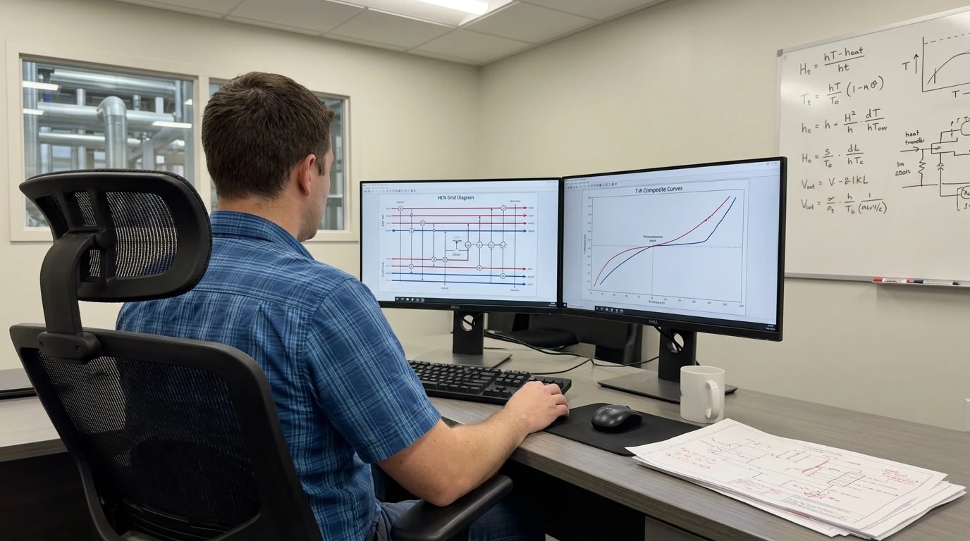
Designing and retrofitting complex heat exchanger networks with dozens of streams requires advanced computational tools. Modern thermal design teams and process engineers rely on specialised software platforms to perform these complex thermodynamic calculations.
Editorial Review of Commercial Synthesis Software
In the field of thermal engineering and process integration, several software platforms are widely used to model and optimise heat exchanger networks:
- Aspen Energy Analyser: Industry professionals widely use this tool to perform pinch analysis, construct composite curves, and design heat exchanger networks. It integrates with process simulators to calculate heat exchanger capital costs, utility costs, and greenhouse gas emissions, allowing engineers to quickly evaluate multiple design options.
- PinCH: Developed by the Lucerne University of Applied Sciences and Arts, this dedicated tool is widely used for continuous and batch process integration. It features a clear, step-by-step user interface that guides thermal design teams through stream extraction, energy targeting, and the practical design of heat exchanger networks using the grid diagram.
- SuperTarget: Process design engineers frequently use this established pinch analysis package to perform multi-utility optimisation. It is highly valued for its ability to model complex, multi-period operations where stream flows and temperatures vary seasonally or based on power plant load.
- DWSIM: For organisations seeking open-source options, this CAPE-OPEN compliant chemical process simulator includes modules that can be paired with custom spreadsheets to perform basic pinch analysis and heat integration studies.
Independent Engineering Analysis
Thermal design teams typically select a software package based on the scale of the facility and the complexity of the utility systems. While commercial packages offer advanced optimisation algorithms that can automatically generate cost-optimised HEN designs, experienced process engineers understand that software tools cannot replace engineering judgement.
In practice, automated algorithms often produce highly integrated network designs that satisfy the mathematical energy targets but are difficult to operate, maintain, or physically fit within the layout of an existing power plant. Successful retrofits require balancing thermodynamic ideals with practical constraints such as physical piping distances, pressure drop limitations, and safety requirements. Independent engineering studies are essential to ensure that the designed networks are both thermodynamically optimal and practically viable.
Practical Case Studies: Waste Heat Recovery in Utility Plants
Analysing real-world applications of pinch analysis demonstrates its practical value in different power generation and heavy industrial contexts. These cases show how systematic heat integration translates into significant fuel savings and reduced environmental impact.
Case Study 1: Large-Scale Industrial Utility Integration
At a major chemical and utility site in Germany, a comprehensive pinch analysis was conducted to address rising fuel costs and impending carbon tax mandates. The facility operated multiple steam-generating boilers and a combined heat and power system.
The pinch study identified multiple heat exchangers that were transferring high-temperature heat across the pinch boundary, violating the core rules of pinch design. By systematically reorganising the heat exchanger network, the plant achieved the following results:
- A coal-fired power station on the site was completely shut down.
- The capacity of an adjacent oil-fired power station was reduced from 600 MW to 300 MW.
- Steam savings of 1,400 t/h were realised across the network.
- Plans to install two expensive flue gas denitrification (DeNOx) and desulphurisation (DeSOx) plants were cancelled, as the reduced fuel combustion automatically brought emissions within regulatory limits.
Case Study 2: Refinery Expansion and Cogeneration Optimisation
During the expansion of the Pennzoil residual catalytic cracking (RCC) and sulphuric acid alkylation units at the Atlas Refining facility in Shreveport, process engineers faced tight constraints on utility capacity and environmental emissions. The engineering team utilised pinch analysis to design the integration of the expansion units with the existing utility systems.
The pinch analysis identified optimal points for process-to-process heat exchange and determined the exact steam pressure levels required from the cogeneration plant. The systematic design approach prevented the need to install additional boiler capacity. The heat integration resulted in:
- An estimated net energy savings of $13.7 million over a ten-year operating period.
- Significant reductions in cooling tower heat load, which freed up cooling capacity for other process units.
- A major reduction in carbon emissions, helping the refinery meet local environmental compliance targets.
These case studies highlight that whether retrofitting an existing utility network or designing a new plant expansion, pinch analysis provides a systematic path to cutting waste heat, lowering operating costs, and reducing carbon emissions.
This article reflects the independent analysis and editorial opinion of EnerTherm Engineering. Product names, trademarks, and brands mentioned belong to their respective owners. EnerTherm Engineering is not affiliated with, endorsed by, or a licensee of any third-party software or product mentioned unless explicitly stated.

Managing Director — EnerTherm Engineering
Dr. François Pierrel is Managing Director of EnerTherm Engineering with over two decades of expertise in thermal design, heat transfer, and industrial energy optimisation. He holds a PhD in Heat Transfer from Cranfield University and a Post-Doctorate from Heriot-Watt University.
