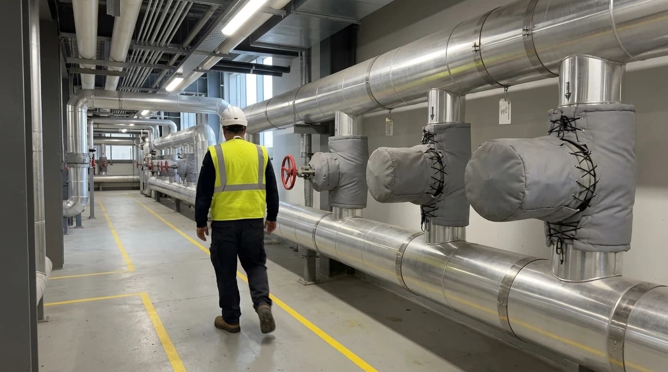
Optimise Process Plant Thermal Efficiency by Up to 14%
Achieving over 1,200 MWh in annual thermal fuel savings with paybacks under two years.
Process plant thermal efficiency is a quantitative thermodynamic metric defining the ratio of useful thermal energy output to the total fuel or heat input across an industrial facility's generation, distribution and recovery networks. Energy-intensive manufacturing operations, including pulp mills, chemical plants, oil refineries and pharmaceutical factories, consume substantial quantities of fuel to generate steam, hot water and thermal fluid. Much of this energy is lost through inefficient utility distribution, uninsulated piping, boiler flue gases and unrecovered low-grade process heat.
Optimising process plant thermal efficiency by up to 14% directly addresses these systemic losses, yielding measurable fuel-cost reductions and ensuring compliance with stringent carbon limits. This technical explainer examines the structured engineering methodology required to audit, model, design and verify high-impact thermal recovery networks in energy-intensive industries.
The Regulatory and Economic Imperatives Under the UK ETS and CCA
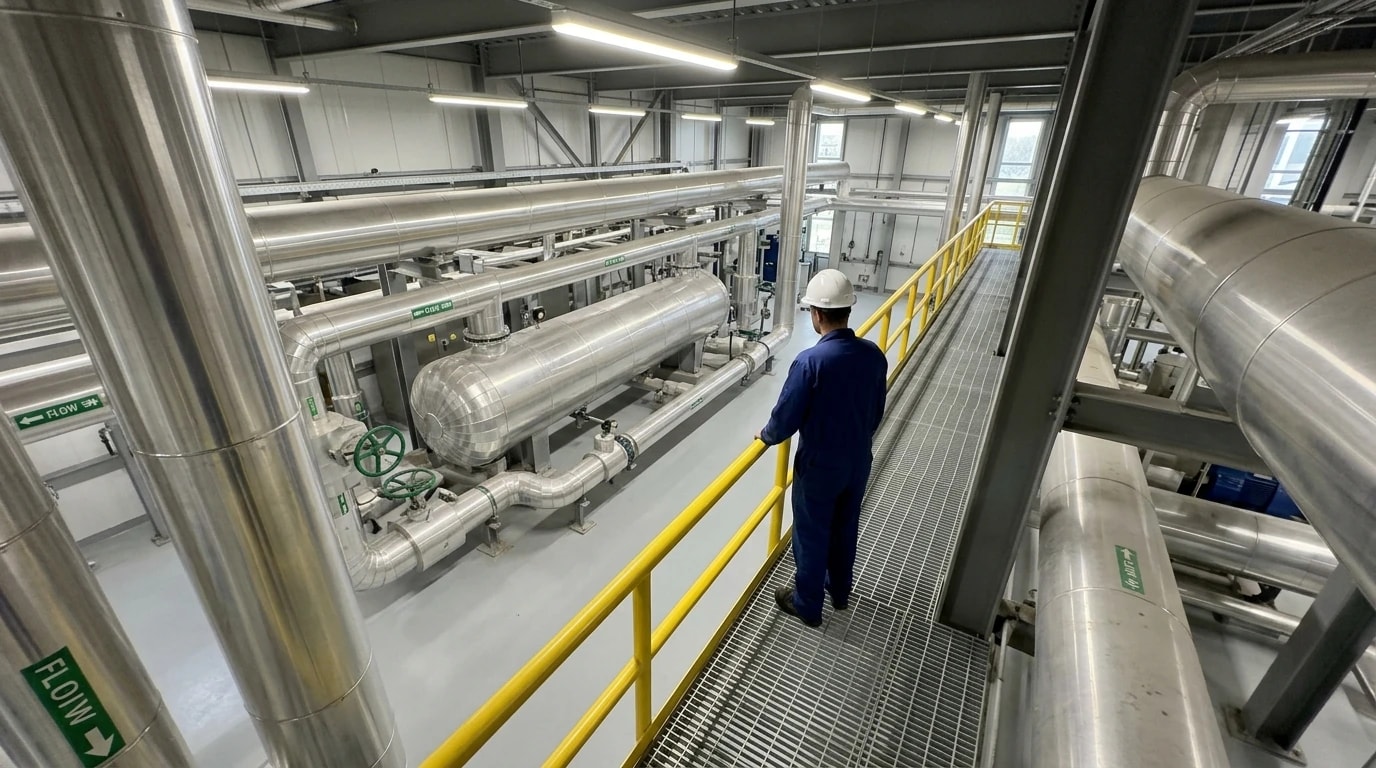
Energy-intensive manufacturing sectors face growing pressure from both volatile fuel markets and tightening environmental legislation. Under the UK Emissions Trading Scheme (UK ETS), industrial facilities exceeding their allocated carbon limits must purchase allowances, creating a direct financial penalty for inefficient fuel combustion.
Climate Change Agreements (CCA)
To mitigate these costs, eligible energy-intensive operations participate in Climate Change Agreements (CCAs). A CCA allows businesses to secure a reduction of up to 92% in the Climate Change Levy (CCL) on electricity, up to 89% on natural gas and solid fuels (such as coal), and up to 77% on liquefied petroleum gas (LPG). To qualify for and maintain these discounts, facilities must meet pre-determined, legally binding targets for energy efficiency and carbon reduction.
Primary Energy Savings and Payback
In thermal-intensive sectors like pulp and paper, process steam can account for over 50% of total operating costs. Improving process plant thermal efficiency by up to 14% through structured thermal engineering projects is a highly reliable pathway to meeting these CCA targets. Experience shows that these efficiency projects deliver rapid capital payback; a standard process integration or heat recovery retrofit typically achieves full capital payback in under 2 years while reducing Scope 1 emissions and eliminating exposure to UK ETS carbon fines.

Map every energy and material flow in your process with detailed heat and mass balance calculations — the foundation for any optimisation or design project.
Rigorous Energy Audits via BS EN 16247-1 and BS EN 16247-3
Before implementing any heat recovery technology, process engineers must establish a clear, data-driven baseline. Superficial energy assessments often miss the complex thermodynamic interactions between different process units, leading to designs that fail to achieve their predicted savings. High-fidelity energy auditing relies on structured, standardised protocols.
The BS EN 16247 Auditing Standards
To ensure thermodynamic rigour, process energy audits must conform to European and British auditing standards:
- BS EN 16247-1:2022 (Energy audits - Part 1: General requirements): Establishes the general principles, common methodology and standard deliverables for all energy audits, ensuring data quality and clear reporting structures.
- BS EN 16247-3:2022 (Energy audits - Part 3: Processes): Focuses specifically on industrial production lines, chemical processes and utility networks. It provides detailed instructions on how to collect process data, handle fluctuating batch demands and account for process constraints such as safety, product quality and environmental regulations.
Integration with ISO 50001
These process-level auditing standards act as the execution mechanism for global energy management systems, specifically BS EN ISO 50001:2018+A1:2024. This standard requires organisations to conduct a formal 'energy review' to identify Significant Energy Uses (SEUs), establish energy performance indicators (EnPIs) and monitor performance over time.
By executing a BS EN 16247-3 process audit, engineers map energy distribution across the plant, establishing a secure technical foundation for continuous improvement under the BS EN ISO 50001 Plan-Do-Check-Act (PDCA) cycle.
| Auditing and Management Standard | Specific Focus Area in Thermal Plants | Key Deliverables and Compliance Requirements |
|---|---|---|
| BS EN 16247-1:2022 | General principles, commercial boundary definition and audit planning. | Quality management of audit, structured energy balance frameworks. |
| BS EN 16247-3:2022 | Detailed industrial process mapping, mass flow tracking and waste heat profiling. | Energy flow maps, process-specific energy-saving opportunities and operational constraints. |
| BS EN ISO 50001:2018+A1:2024 | Long-term corporate energy management, policy development and continuous performance tracking. | Formal Energy Review, validated EnPIs, documented baseline models and climate action risk assessments. |
Thermodynamic Modelling: The Heat and Mass Balance (HMB) Foundation
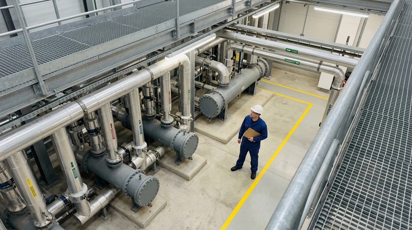
Every successful thermal optimisation project relies on a highly accurate Heat and Mass Balance (HMB). This HMB tracks every unit of matter and energy entering and leaving a defined process boundary, ensuring that the first and second laws of thermodynamics are satisfied across the facility.
EnerTherm's 11-Step HMB Methodology
EnerTherm Engineering utilises a proprietary 11-step engineering methodology to standardise the transition from raw field measurements to validated thermal designs:
- Initial Data Acquisition: Thermal engineers collect historical operational logs, process drawings, Piping and Instrumentation Diagrams (P&IDs) and electrical utility data.
- Thermodynamic Boundary Definition: Establishing strict physical and thermodynamic boundaries around individual unit operations to isolate energy flows.
- Sensor Validation and Calibration: Verifying the calibration and accuracy of existing field instrumentation to ensure the reliability of raw temperature, pressure and flow data.
- Species-Level Mass Balance Formulation: Writing conservation equations for all chemical species and phases (solid, liquid and vapour) crossing process boundaries.
- Enthalpy Balance and Energy Accounting: Calculating the total enthalpy of every entering and leaving stream, factoring in sensible heat, latent heat of phase change and chemical heats of reaction.
- Steady-State Simulation Construction: Thermal design teams construct a steady-state simulation model of the facility. To predict phase changes and thermodynamic properties, process engineers typically rely on industry-standard simulation platforms such as Aspen Plus, HYSYS or the open-source DWSIM simulator.
- Model Calibration and Validation: Adjusting simulation parameters to match actual plant operating data within a target tolerance of less than ±5% across all major streams.
- Sankey Energy Mapping: Generating detailed Sankey energy maps to visually identify the magnitude and location of thermal losses, such as boiler stack losses or unrecovered condensate.
- Transient and Dynamic Modelling: For batch operations, engineers develop dynamic simulations to capture cyclic temperature profiles and identify opportunities for thermal energy storage.
- Energy Conservation Measure (ECM) Simulation: Modelling proposed modifications, such as adding heat exchangers or changing steam distribution pressures, directly within the validated simulation to predict net savings.
- PFD Finalisation and Stream Tables: Delivering a 'single-source-of-truth' Process Flow Diagram (PFD) containing fully embedded stream tables, validated mass and energy balances and prioritised capital investment plans.
This rigorous, data-driven approach ensures that proposed heat recovery projects do not negatively impact upstream chemical kinetics or downstream product quality. For example, in pharmaceutical manufacturing, optimisation must respect Good Manufacturing Practice (GMP) standards, whilst in food and beverage processing, systems must satisfy Hazard Analysis Critical Control Point (HACCP) safety protocols.

Map every energy and material flow in your process with detailed heat and mass balance calculations — the foundation for any optimisation or design project.
High-Impact Waste Heat Recovery: Compressor Retrofit Case Study
Air compressors are standard utility systems in almost all industrial facilities, yet they are highly inefficient from a thermal perspective. Up to 94% of the electrical energy supplied to an industrial oil-injected screw compressor is converted directly into heat and rejected via the cooling oil circuit.
Case Study: Processing Facility WHR Retrofit
To illustrate the value of waste heat recovery (WHR), process design teams completed a detailed, investment-grade evaluation of a compressor WHR retrofit in an industrial processing facility.
The Technology and Sizing Equation
The project team installed a highly efficient plate heat exchanger (PHE) on the oil circuit of two oil-injected screw compressors. The PHE was sized using the classical heat transfer rate equation:
Q=U⋅A⋅ΔTlmwhere:
- Q is the thermal energy transfer rate in kW.
- U is the overall heat transfer coefficient in W/m2⋅K, influenced by fluid velocities and plate geometry.
- A is the total heat transfer area in m2.
- ΔTlm is the logarithmic mean temperature difference in °C or K.
To calculate the logarithmic mean temperature difference, engineers use the following equation:
ΔTlm=ln(ΔT1/ΔT2)ΔT1−ΔT2where:
- ΔT1 is the temperature difference between the two fluid streams at one end of the heat exchanger (e.g. hot oil inlet to warm process water outlet).
- ΔT2 is the temperature difference between the two fluid streams at the other end of the heat exchanger (e.g. hot oil outlet to cold process water inlet).
This design allowed the engineering team to select a PHE that maximised heat recovery, preheating process water from 15°C to 65°C while preventing compressor oil from dropping below 72°C—the critical threshold to avoid condensation in the oil circuit.
Performance and Financial Metrics
The system achieved a verified mean recovered thermal power of 165 kW (against a design target of 170 kW), delivering significant operational benefits:
- Annual Fuel Savings: 1,260 MWh of natural gas, representing a 7.8% reduction in the plant's overall thermal energy demand.
- Carbon Mitigation: 307 tonnes of CO₂ equivalent (CO₂e) emissions avoided per year.
- Capital Cost: A total project cost of €95,000 for hardware, piping, controls and installation.
- Operational Cost Savings: €54,600 in annual fuel savings.
- Simple Payback Period: 1.7 years, meeting corporate thresholds for rapid capital recovery.
Advanced Thermal Optimisation: Pinch Analysis and Mill-Wide Integration
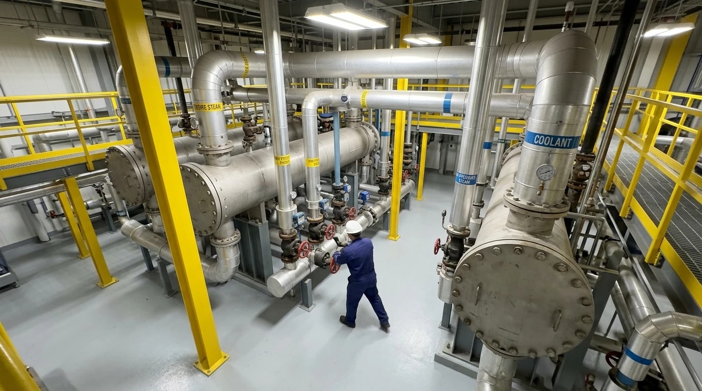
Upgrading individual unit operations in isolation can lead to unintended inefficiencies elsewhere in the plant. For instance, in a pulp mill, adding a local heat exchanger to cool a hot effluent stream may reduce the inlet temperature to the wastewater treatment plant, forcing operators to expend additional energy heating biological reactors to maintain activity.
The Methodology of Pinch Analysis
To prevent system-wide errors, engineers use Pinch Analysis to design integrated heat exchanger networks (HENs), treating the entire facility as an interconnected thermodynamic system.
This process maps all hot streams (requiring cooling) and cold streams (requiring heating) onto a single temperature-enthalpy graph to generate 'Composite Curves'. The point where these curves come closest together is the 'Pinch Temperature'.
Pinch Temperature=TpinchThe Pinch divides the process plant into two distinct thermodynamic regions:
- Above the Pinch: An overall heat sink requiring only hot utilities (such as steam).
- Below the Pinch: An overall heat source requiring only cold utilities (such as cooling water).
To design a thermodynamically optimal process, engineers must adhere to three core rules:
- Do not transfer heat across the Pinch.
- Do not use cold utilities above the Pinch.
- Do not use hot utilities below the Pinch.
Industrial Applications and Savings Potential
Applying these rules across different energy-intensive sectors yields significant savings:
Pulp and Paper Manufacturing
In paper mills, chemical pulping and drying are highly heat-intensive. Black liquor evaporation consumes substantial energy, typically utilising complex multiple-effect evaporators (MEEs). By applying Pinch Analysis to the entire process, including the steam-heated dryer sections, mills routinely reduce steam consumption by an average of 17%, equivalent to saving approximately 100 MMBtu/h of thermal energy per facility.
Chemical Processing Plants
In chemical facilities, exothermic reaction heat is often wasted whilst distillation columns consume massive quantities of steam. Pinch Analysis allows engineers to capture reaction energy to drive the reboilers of downstream distillation columns, frequently eliminating the need for primary steam in those units.
Oil Refineries
Crude oil distillation units rely on a complex preheat train to warm incoming crude before it enters the atmospheric furnace. Process engineers use Pinch Analysis to design optimal heat exchanger configurations that recover heat from hot product streams (such as diesel, gas oil and residue), reducing furnace fuel consumption by up to 12%.
Measurement and Verification: Formulating Bankable Investment Cases via IPMVP Option B
Industrial executives and financial boards require high confidence that proposed capital projects will deliver their estimated savings. To build a 'bankable' investment case, process engineers must apply structured measurement and verification (M&V) protocols to prove savings with high statistical accuracy.
The IPMVP Option B Protocol
The International Performance Measurement and Verification Protocol (IPMVP) is the global standard for verifying energy and water savings. For thermal recovery projects, such as waste heat recovery installations, engineers typically apply IPMVP Option B (Retrofit Isolation: All Parameter Measurement).
Option B requires defining a strict measurement boundary around the retrofit equipment. Engineers must measure all independent variables and energy streams within this boundary continuously over both baseline and post-retrofit periods, isolating the performance of the heat recovery system from unrelated changes in the wider plant.
Quantifying Measurement Uncertainty
An energy-saving claim is incomplete without a clear statement of its statistical uncertainty. To calculate this, engineers perform detailed error propagation analyses in accordance with standard codes:
- ASME PTC 19.1-2018 (Test Uncertainty): Defines the standard procedures for identifying and combining systematic (bias) and random (precision) errors in performance test measurements.
- ISO 5168:2005 (Measurement of fluid flow - Procedures for the evaluation of uncertainties): Provides specific mathematical models for calculating uncertainty in liquid and steam flow rates.
By combining instrument-specific calibration tolerances (for temperature sensors, flow meters and pressure transducers) using a root-sum-square (RSS) approach, engineers calculate the combined expanded uncertainty (Uc):
Uc=k⋅∑(ui)2where:
- ui represents the individual standard uncertainty components.
- k is the coverage factor, typically set to k=2 to define a 95% confidence interval.
In the compressor waste heat recovery case study discussed above, applying this rigorous uncertainty analysis proved that the combined expanded uncertainty of the recovered energy was just ±3.6% (k=2).
This high level of accuracy gives plant managers, lenders and corporate finance committees the absolute assurance required to approve investments in large-scale thermal efficiency upgrades, transforming compliance requirements into highly profitable, low-risk engineering assets.
This article reflects the independent analysis and editorial opinion of EnerTherm Engineering. Product names, trademarks, and brands mentioned belong to their respective owners. EnerTherm Engineering is not affiliated with, endorsed by, or a licensee of any third-party software or product mentioned unless explicitly stated.

Managing Director — EnerTherm Engineering
Dr. François Pierrel is Managing Director of EnerTherm Engineering with over two decades of expertise in thermal design, heat transfer, and industrial energy optimisation. He holds a PhD in Heat Transfer from Cranfield University and a Post-Doctorate from Heriot-Watt University.
