Why Cleanroom Heat Recovery Must Control Air Leakage
BS EN 308:2022 compares leakage, pressure drop and EATR for safe designs.
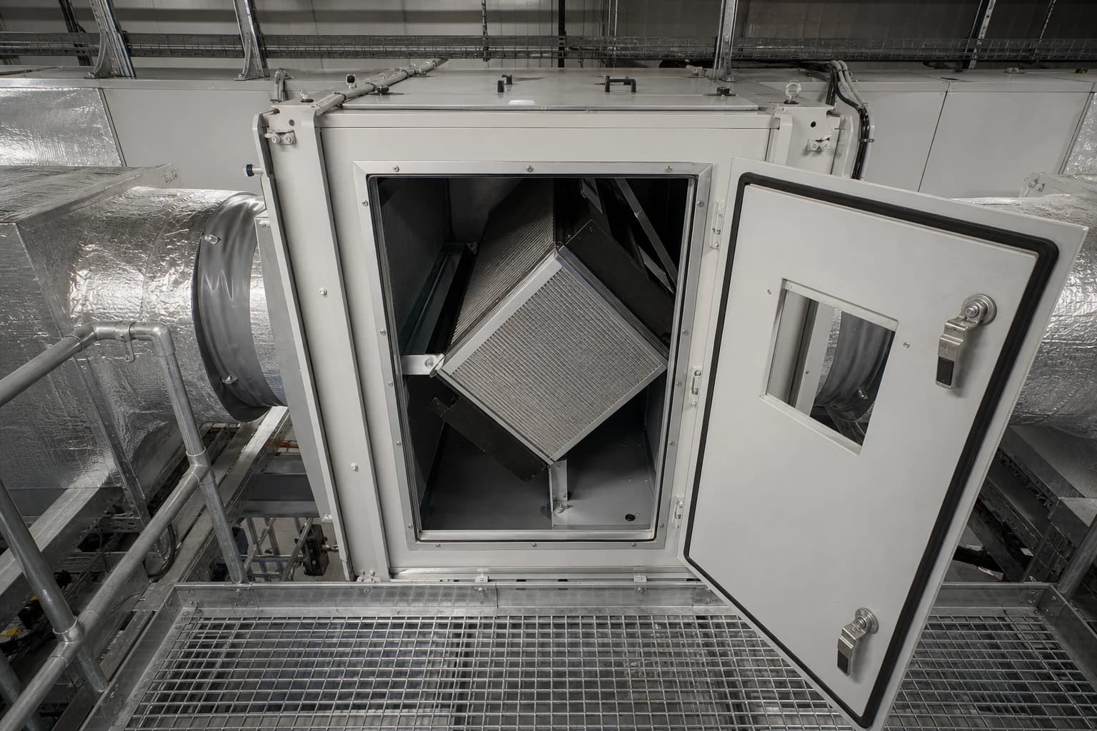
A cleanroom HVAC heat-recovery system transfers thermal energy from extract air to incoming outdoor air while maintaining safe separation between the two airstreams. In a pharmaceutical cleanroom, that separation affects energy performance and contamination control.
Ventilation plant in pharmaceutical, biotech, semiconductor and advanced-manufacturing facilities runs at high air volumes for long periods, often continuously. Its extract air contains recoverable heating energy in winter and cooling potential during warmer weather. That creates a strong case for recovery, but also a design risk: an uncontrolled path from extract to supply can transfer particles, moisture, odours, solvents or process residues towards the cleanroom.
Temperature efficiency alone does not establish suitability. A heat-recovery component can deliver an impressive thermal result while imposing a leakage direction or operating mode that conflicts with cleanroom pressure control. Engineers need to assess the device within the air-handling system, pressure cascade and verification plan.
Why cleanroom HVAC heat recovery depends on leakage control
Heat recovery sits between two streams with different duties. The supply path must deliver filtered, conditioned air at the required volume and pressure. The extract path removes heat, moisture and contaminants from the cleanroom or surrounding spaces. The system must recover energy without combining those duties.
Leakage changes both air quality and airflow quantity. Extract air entering the supply stream dilutes the outdoor-air fraction and can carry contaminants upstream of terminal filtration. Supply air leaking into extract may protect supply-air quality, but wastes conditioned air, increases fan demand and can disturb the balance that maintains room pressure.
Leakage direction follows the actual pressure difference across the heat-recovery section, not a simplified schematic. Fan position, filter loading, damper positions and variable-speed operation can all change local static pressure.
Static leakage through a fixed barrier
Plate heat exchangers use fixed plates to separate adjacent air passages. They avoid the rotating transfer mechanism associated with thermal wheels, but their airstreams are not automatically airtight.
Potential leakage paths include:
Plate seals and perimeter gaskets
Heat-exchanger frame and casing joints
Access doors and inspection panels
Duct connections either side of the heat exchanger
Damper interfaces used for bypass or frost protection
A plate heat exchanger can perform acceptably at its nominal design flow while its leakage direction reverses during low-flow operation, start-up, frost protection or filter loading. The cleanroom duty therefore needs a defined pressure relationship across the heat exchanger in every intended mode.
Carryover in rotary thermal wheels
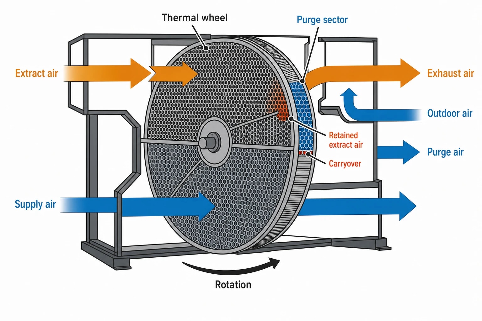
A rotary thermal wheel has a different risk mechanism. Its matrix alternately passes through extract and supply air. Air retained in the matrix can rotate into the supply path. This is carryover.
A correctly designed purge sector uses a controlled flow of outdoor air to displace retained extract air into the exhaust side before that part of the wheel reaches the supply airstream. Purge control can reduce carryover substantially, but also reduces recovered duty and affects extract-fan demand. The pressure relationship, wheel speed, seal condition and purge setting all matter.
CIBSE guidance distinguishes carryover from seal leakage. Both require assessment. Stopping a thermal wheel may stop regenerative heat transfer, but does not remove leakage across its seals while the supply and extract fans continue to operate.

Pinch analysis identifies the thermodynamic minimum energy requirement of your process — then designs the heat exchanger network to achieve it.
BS EN 308:2022 makes leakage a performance requirement
BS EN 308:2022 provides test procedures for air-to-air heat-recovery components, including recuperators, regenerators and systems with an intermediary heat-transfer medium. It requires assessment beyond temperature efficiency.
The standard covers temperature and humidity efficiency, supply-side and exhaust-side pressure drop, internal and external leakage, Exhaust Air Transfer Ratio, Outdoor Air Correction Factor and auxiliary energy. These results give design teams a more useful selection basis than a single efficiency claim.
EATR and OACF describe different parts of the problem
Exhaust Air Transfer Ratio, EATR, indicates the proportion of extract air transferred into supply air. In a contamination-sensitive application, it is the measure most directly linked to extract-air migration towards the cleanroom.
Outdoor Air Correction Factor, OACF, compares outdoor air entering the recovery component with supply air leaving it. It helps show whether leakage has changed the amount of genuine outdoor air delivered downstream.
The two values must be read together. EATR addresses transfer from extract towards supply. OACF identifies the airflow imbalance caused by transfer between streams. Eurovent guidance notes that both affect supply-air quality, system balance and fan energy.
Declared performance measureWhat it showsWhy it matters in a cleanroomTemperature efficiencyHeat transferred between airstreamsIndicates heating or cooling recovery potentialHumidity efficiencyMoisture transfer between airstreamsRelevant where humidity control is critical or moisture transfer is unacceptableSupply and extract pressure dropResistance through each side of the heat exchangerInfluences fan duty and available pressure marginStatic internal leakageAir crossing the heat exchanger at a stated pressure differenceImportant for plate heat exchangers and other physically separated devicesEATRExtract air entering supply airDirectly relevant to contamination transferOACFChange in outdoor-air flow through the recovery sectionSupports outdoor-air and pressure-balance calculationsAuxiliary energyEnergy used by pumps, drives or supporting equipmentPrevents recovered-duty figures from overstating net savings
A procurement specification should request these values at the actual air-handling-unit duty rather than accepting a supplier’s preferred test point. This includes design flow, low-flow operation and operating conditions used during seasonal control.
Product test results do not prove the installed system
BS EN 308:2022 covers laboratory and field test procedures for the heat-recovery component or section. It cannot confirm the complete installed arrangement.
Site conditions can differ materially from the declared test point. Duct resistance, fan arrangement, dirty filters, bypass dampers, pressure controls and commissioning adjustments may all change the pressure difference through the recovery section. The room cascade can then become vulnerable even though the selected device meets its declared performance.
The specification and commissioning plan should therefore define:
The extract-air classification and contaminants associated with each exhaust stream.
Which extract streams may use direct air-to-air recovery and which require physical separation.
The maximum acceptable extract-to-supply transfer for each application.
The required pressure direction through the heat-recovery section in each operating mode.
The verification tests, instrument locations and alarm response required after installation.
Pressure cascades make air leakage a cleanroom risk
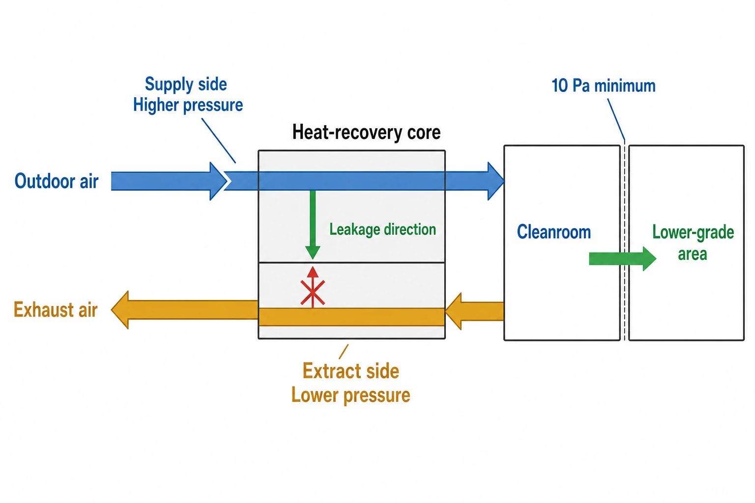
Pressure cascades direct airflow from cleaner areas towards areas of lower cleanliness, unless a process requires containment in the opposite direction. They protect the product, process or operator by controlling the route air takes between rooms.
For sterile medicinal-product manufacture, EU GMP Annex 1 states that cleanrooms should receive filtered air that maintains positive pressure and/or airflow relative to a lower-grade background environment under all operating conditions. Clause 4.16 gives a minimum 10 Pa differential between adjacent rooms of different grades as guidance.
That figure concerns room boundaries. A heat-recovery section can still undermine it indirectly by changing supply and extract air volumes, increasing pressure drop or creating uncontrolled transfer between airstreams.
Pressure direction needs checking beyond design duty
A heat-recovery device must retain a safe pressure relationship at more than one operating point. The review should include:
Full production airflow
Reduced airflow or setback operation
Filter loading towards final pressure drop
Frost protection and defrost operation
Heat-recovery bypass mode
Supply or extract fan failure response
Start-up and shutdown sequences
A common objective is to maintain a higher pressure on the outdoor-air side than the exhaust side across the heat exchanger. Any leakage then tends to move from supply to exhaust, protecting supply-air quality. That choice has an energy cost, as treated air bypasses the intended supply route and may increase fan power. The project energy model should include that cost.
Room monitoring must connect to plant behaviour
Annex 1 calls for air-pressure-difference indicators between cleanrooms and adjacent areas, and requires continuous monitoring and recording of critical pressure differentials. A warning system is needed for a supply-air failure or a fall below the defined pressure limit.
Heat recovery should be included in the cause-and-effect review behind those controls. A rising filter pressure drop can change fan speed and damper positions. A frost sequence can restrict one airstream. A failed damper actuator can reverse the intended pressure direction through the heat exchanger. Each event can affect room differential pressure before it appears as a clear plant fault.
Pressure monitoring confirms the overall relationship between rooms. Airflow visualisation separately checks the movement of air around doors, equipment and transfer points. Both are useful after a significant heat-recovery modification.

Pinch analysis identifies the thermodynamic minimum energy requirement of your process — then designs the heat exchanger network to achieve it.
Selecting cleanroom HVAC heat recovery technology
The safest choice depends on extract-air risk, required recovery duty, pressure margin, available plant space and maintenance access. Stream segregation comes first. Thermal efficiency follows.
Plate heat exchangers
Plate heat exchangers transfer heat across a fixed barrier. They have no rotating matrix moving from extract to supply, which makes them attractive where direct air transfer requires close control.
Their limitations are practical. Seals, casing integrity and local pressure differences still determine leakage. Frost protection can reduce recovery, alter airflow and introduce bypass operation. Designers should specify how the frost-control sequence preserves supply and extract balance, not merely how it protects the plate pack.
Rotary thermal wheels
Rotary thermal wheels can achieve high temperature efficiency within a compact footprint. Some designs also recover moisture, which can affect humidification and dehumidification demand.
Their use demands assessment of both carryover and seal leakage. A suitable arrangement needs effective seals, a correctly positioned purge sector, stable pressure control and verification across the intended range of wheel and fan speeds. A low EATR declaration does not replace assessment of the extract hazard or installed pressure regime.
Where an extract stream contains contaminants that must be excluded from supply air, designers should establish whether a wheel is acceptable through the facility’s contamination-control strategy. Energy recovery should not weaken stream segregation.
Run-around coil systems
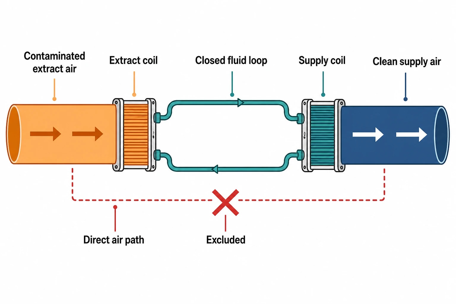
A run-around coil system places one coil in the extract airstream and another in the supply airstream. A pumped heat-transfer circuit connects the coils, allowing the air-handling units to remain physically separate and, where necessary, widely spaced.
This arrangement removes direct air-to-air transfer through the recovery mechanism. It can suit high-hygiene applications and layouts with remote supply and extract plant. The energy assessment must include coil pressure drop, pump energy, fluid-circuit integrity, freeze protection, drainage and maintenance access.
TechnologyAirstream separationMain design issuePlate heat exchangerFixed barrier between adjacent airstreamsSeal leakage and pressure direction during normal and frost modesRotary thermal wheelShared rotating matrixCarryover, seal leakage, purge control and fan configurationRun-around coilSeparate coils connected by a heat-transfer circuitPump energy, coil pressure drop and fluid-circuit maintenance
Pinch analysis needs contamination constraints
Pinch Analysis identifies feasible heat recovery by matching heat sources and sinks within temperature constraints. Cleanroom extract air can be an attractive low-temperature source because ventilation plant operates whenever production requires environmental control.
The maximum theoretical recovery target may conflict with the permitted recovery route. A stream that cannot share a direct air-to-air heat exchanger with supply air can still transfer energy through a run-around coil or serve another suitable heat sink.
Segregate extract streams before thermal targeting
Cleanroom exhaust should be classified before building the heat-recovery model. The assessment should distinguish general room extract from streams associated with potent compounds, solvents, biological materials, process equipment or local extraction. The classification should come from the process risk assessment and contamination-control strategy.
A practical sequence is:
Map supply, extract, relief and utility conditions across the operating year.
Separate extract streams by contamination and process risk.
Exclude direct recovery matches that create an unacceptable transfer route.
Compare recovered thermal duty with fan, pump, frost-control and control energy.
Check supply and extract airflows against room pressure requirements.
Define the inspection and verification tasks needed to retain intended leakage performance.
This method places safety constraints inside the energy target. It prevents an optimistic recovery calculation from relying on a heat-exchanger configuration that cannot operate safely in the cleanroom.
Verification keeps leakage performance credible
ISO 14644-4:2022 sets the framework for creating new, refurbished and modified cleanrooms from requirements through design, construction and start-up. A heat-recovery retrofit should follow the same disciplined route: define the requirement, design the pressure relationships, construct the arrangement, then prove performance at start-up.
ISO 14644-16:2019 provides guidance on optimising energy use and maintaining energy efficiency in new and existing cleanrooms and separative devices. It places energy performance alongside cleanroom performance rather than treating it as an isolated plant-room calculation.
Commissioning should confirm actual supply, extract and relief flows, pressure differences through the recovery section, room differential pressures, control response and alarm behaviour. Tests need to cover operating modes that carry risk, including reduced flow, bypass, frost protection and fan-speed changes.
Maintenance access also affects leakage control. Inspection points should allow teams to examine seals, casing panels, dampers, wheel purge arrangements, coils, condensate drainage and differential-pressure instruments. Trend records relating room pressure to fan speed, filter condition and heat-recovery status can identify declining pressure margin before it reaches an alarm limit.
This article reflects the independent analysis and editorial opinion of EnerTherm Engineering. Product names, trademarks, and brands mentioned belong to their respective owners. EnerTherm Engineering is not affiliated with, endorsed by, or a licensee of any third-party software or product mentioned unless explicitly stated.

Managing Director — EnerTherm Engineering
Dr. François Pierrel is Managing Director of EnerTherm Engineering with over two decades of expertise in thermal design, heat transfer, and industrial energy optimisation. He holds a PhD in Heat Transfer from Cranfield University and a Post-Doctorate from Heriot-Watt University.
