Pharmaceutical Industry Audits Recover 65-85% Heat
Recovering up to 85% of process waste heat while optimising steam use under EU GMP.
A pharmaceutical industry energy audit is a systematic evaluation of energy flows within a drug manufacturing facility designed to identify waste heat recovery opportunities without compromising Good Manufacturing Practice (GMP) standards. This specialised assessment, typically conducted in accordance with BS EN 16247-1:2022 and BS EN 16247-3:2022, provides facilities directors and utility engineers with a detailed thermodynamic baseline. By mapping energy inputs and identifying waste streams, an audit establishes a clear path to recover 65 to 85 per cent of waste heat from high-intensity processes.
Pharmaceutical manufacturing facilities operate under stringent validation criteria where sterile boundaries and environment-critical parameters cannot be compromised. Historically, this priority on compliance has led to the over-specification of utility systems, resulting in continuous boiler operation and excessive cleanroom ventilation. A systematic thermal audit reconciles these energy-intensive operations with modern sustainability mandates, demonstrating that regulatory compliance and heat recovery can coexist.
Cleanroom HVAC and Environmental Control: The Primary Energy Sinks
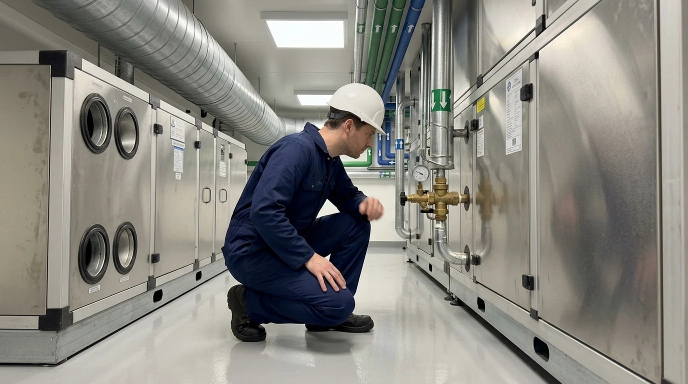
Heating, ventilation, and air conditioning (HVAC) systems represent the largest single consumer of energy in a pharmaceutical manufacturing facility, typically accounting for 40 to 60 per cent of total site power. In highly sterile environments, this proportion can rise to 75 per cent. The energy intensity of these systems stems directly from the stringent airborne particulate and microbial controls required to protect pharmaceutical products.
High Air Change Rates and Contamination Control
To maintain the required room classifications, cleanrooms operate with exceptionally high air change rates. While standard commercial offices require 2 to 4 air changes per hour (ACH), pharmaceutical cleanrooms often operate between 20 and 600 ACH. Moving this volume of air requires significant electrical energy to overcome the static pressure of multi-stage filtration systems, which include pre-filters, bag filters, and high-efficiency particulate air (HEPA) filters.
The electrical power demanded by a fan motor is proportional to the cube of the airflow rate. Consequently, even a minor over-specification in air change rates leads to a substantial energy penalty.
The Thermal Cost of Constant Conditioning
In addition to fan power, conditioning the supply air imposes a heavy thermal load. Cleanrooms require precise temperature and relative humidity control to prevent product degradation and electrostatic discharge. To achieve this, outdoor makeup air must be cooled below its dew point to remove moisture and then reheated to the target room temperature. This process of simultaneous cooling and reheating consumes vast quantities of steam and chilled water, representing a major source of low-grade thermal waste.

Identify where your plant is losing energy and quantify the savings potential — our audits map every heat source, sink, and waste stream in your facility.
Breaking Boiler Dependence through Systematic Thermal Audits
Many pharmaceutical sites suffer from "boiler dependence" — an operational pattern where steam boilers are kept firing at low loads or in hot standby mode to avoid thermal cycling and startup delays. This practice stems from the critical need for steam during sterilisation, batch heating, and formulation processes.
The Cost of Continuous Boiler Operation
Running centralised steam boilers continuously, even during periods of low production demand, introduces massive efficiency losses. At low firing rates, boilers operate far below their peak design efficiency. Radiation losses, standing losses, and flue gas losses remain relatively constant regardless of boiler load, meaning that low-load operation dramatically increases the fuel consumed per unit of useful steam generated.
Furthermore, maintaining a large steam distribution network under pressure when processes are idle leads to continuous heat loss through uninsulated pipework, flanges, and valves. It also increases the rate of steam condensate generation, which must be managed through steam traps that are themselves prone to failure.
Transitioning to Decoupled Thermal Loops
A systematic thermal audit evaluates the temperature requirements of every thermal sink across the facility. This evaluation frequently reveals that many processes currently supplied by high-temperature steam do not actually require high-grade heat.
By decoupling low-temperature thermal requirements — such as space heating, domestic hot water, and vessel jacket preheating — from the steam network, facilities can transition these loads to hot water loops. This transition allows centralised steam boilers to be shut down during non-production periods, eliminating standing losses and resolving the issues associated with continuous boiler operation.
Thermal Systems Optimisation: Pinch Analysis and Integration
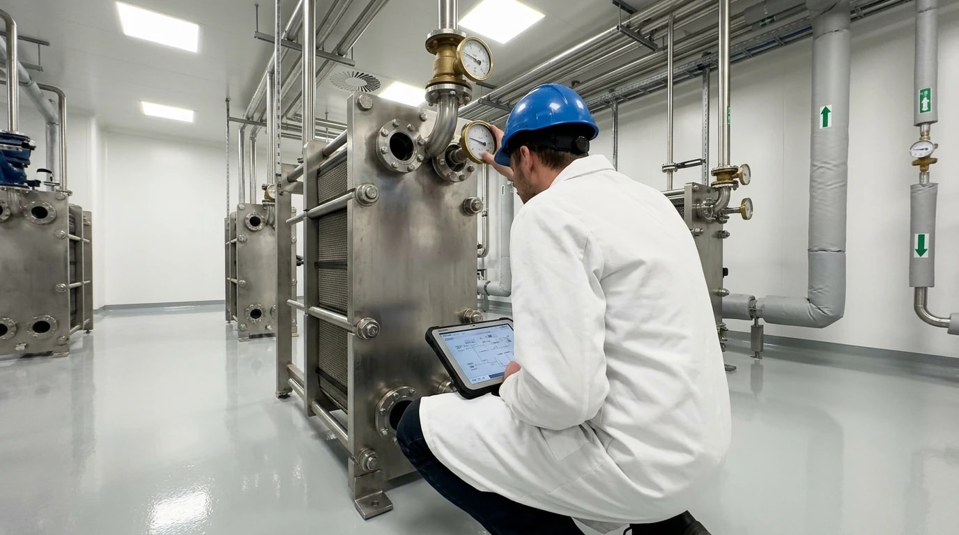
Pinch Analysis is a rigorous thermodynamic methodology used during a pharmaceutical industry energy audit to design highly integrated utility networks. This approach defines the minimum hot and cold utility targets for a facility by analysing the heat transfer opportunities between existing hot and cold process streams.
Mapping the Composite Curves
To perform a Pinch Analysis, engineers collect flow rates, specific heat capacities, and target temperatures for all process streams that require heating (cold streams) or cooling (hot streams). These streams are combined to create Hot and Cold Composite Curves on a Temperature-Enthalpy (T-H) diagram.
The point of closest approach between these two curves is known as the "pinch temperature" or the "pinch." The pinch divides the process into two distinct thermodynamic regions:
- Above the Pinch: This region is a net heat sink and requires only external hot utility (such as steam or high-temperature water).
- Below the Pinch: This region is a net heat source and requires only external cold utility (such as chilled water or cooling tower water).
Directing process heat across the pinch temperature is thermodynamically inefficient. It simultaneously increases the requirement for both external heating and external cooling. By adhering to strict pinch rules, thermal design teams can identify configuration changes that maximise heat integration, effectively matching waste heat sources with heating demands.

Identify where your plant is losing energy and quantify the savings potential — our audits map every heat source, sink, and waste stream in your facility.
Industrial Waste Heat Recovery: Capturing 65 to 85 per cent of Thermal Energy
A comprehensive pharmaceutical industry energy audit targets several high-value thermal waste streams. By capturing this energy and upgrading it using industrial heat pumps, facilities can drastically reduce their reliance on primary steam generation.
Heat Recovery from Sterile Water for Injection (WFI) Systems
Water for Injection (WFI) is a critical utility in pharmaceutical manufacturing, used as a solvent in parenterals and for cleaning sterile equipment. WFI is traditionally produced via multi-effect distillation, which requires heating feed water to high temperatures, or through membrane-based systems. To prevent microbial contamination, WFI loops are typically stored and distributed continuously at temperatures above 80°C.
However, many formulation and filling processes require WFI at ambient or chilled temperatures (typically 15 to 25 °C). To meet this requirement, hot WFI must be cooled at the point of use, discarding substantial thermal energy into the facility's chilled water loop.
An energy audit identifies opportunities to install double-tubesheet heat exchangers to recover this heat. This recovered energy can preheat the incoming cold feed water destined for the WFI generation system. This approach directly reduces the steam required for distillation while simultaneously lowering the cooling load on the central chillers.
Autoclave and Cleanroom Exhaust Heat Recovery
Autoclaves and sterilisers are major sources of high-grade waste thermal energy. During the exhaust cycle, autoclaves vent high-temperature steam and discharge hot condensate to drain. Because drain discharge temperatures are restricted by environmental regulations (often to a maximum of 40 °C in the UK), facilities routinely mix this hot condensate with cold municipal water before disposal, compounding the energy waste.
Installing a dedicated heat recovery system allows this thermal energy to be transferred to a low-temperature loop. This loop can then preheat boiler feed water or support HVAC reheat coils.
Similarly, cleanroom exhaust air is a valuable source of waste heat. Because cleanrooms require high outdoor air exchange rates, a large volume of conditioned air is continuously exhausted from the building.
To recover this energy without risking cross-contamination between the exhaust air and the incoming fresh air stream, thermal design teams often select run-around coil systems. These systems use a closed loop of water or glycol pumped between heat exchangers in the exhaust and supply air ducts, ensuring physical separation of the air streams while recovering up to 60 per cent of the sensible heat.
Upgrading Low-Grade Heat with High-Efficiency Heat Pumps
Low-grade waste heat, such as the heat rejected from refrigeration condensers, cleanroom exhaust, and low-temperature condensate, often lacks the temperature required for direct process reuse. Industrial high-temperature heat pumps (HTHPs) resolve this limitation by lifting the temperature of this waste heat to useful levels, often between 80°C and 120°C.
Because heat pumps transfer existing heat rather than generating it from combustion, they achieve exceptional efficiencies. While a modern condensing gas boiler operates with a Coefficient of Performance (COP) of approximately 0.9, an industrial heat pump recovering low-grade waste heat can achieve COPs of 4.0 to 8.0. This means that for every kilowatt-hour of electricity consumed by the compressor, up to 8 kilowatt-hours of useful thermal energy are delivered back to the facility, reducing fossil-fuel dependence and lowering Scope 1 emissions.
Practical Implementation and Compliance under EU GMP Annex 1 (2022) and ISO 14644-16:2019
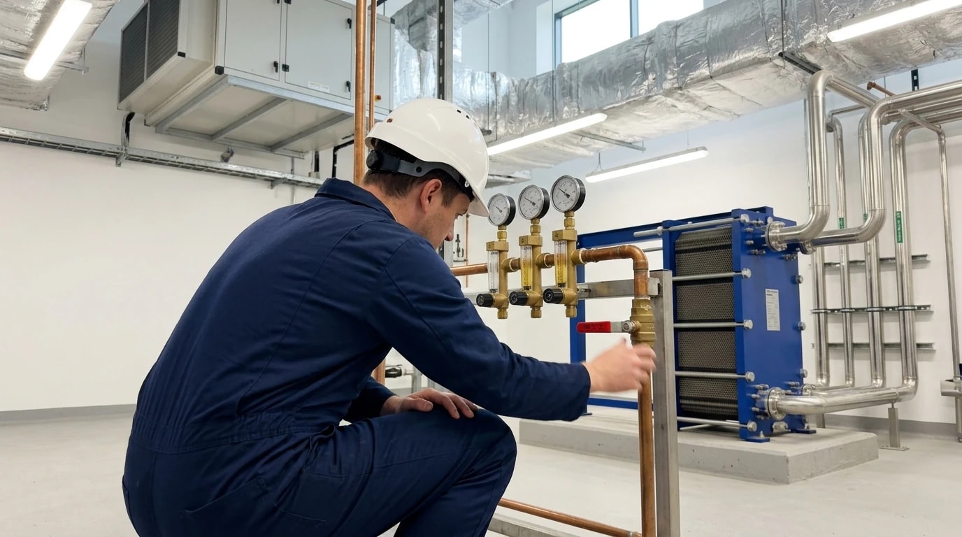
Any energy-saving initiative implemented at a pharmaceutical manufacturing site must prioritise patient safety and product quality above all else. Modified HVAC and thermal systems must remain fully compliant with regulatory standards, including EU GMP Annex 1 (2022) and the ISO 14644 series of cleanroom standards.
Risk-Based Cleanroom Design and ISO 14644-16:2019
ISO 14644-16:2019 outlines clear strategies for optimising energy use in cleanrooms without compromising contamination control. The standard advocates for a risk-based approach, moving away from legacy, arbitrary air change rates and instead sizing ventilation systems based on actual particle generation rates and occupancy patterns.
One of the most effective strategies detailed in ISO 14644-16:2019 is the implementation of variable airflow rates. By equipping fan motors with variable speed drives (VSDs), facilities can program the HVAC system to reduce airflow during non-operational hours (the "at-rest" state).
During these periods of lower occupancy, the particulate generation rate drops significantly, allowing the system to maintain compliant conditions with a fraction of the operational airflow. This reduces both fan power and the thermal load associated with air conditioning.
Preserving Sterility and the Pressure Cascade (Annex 1)
Any modification to cleanroom airflow must strictly preserve the pressure cascades required by Annex 1. To prevent the migration of contaminants from lower-classified zones to highly sterile areas, cleanrooms operate under a positive pressure hierarchy. Annex 1 requires a minimum pressure differential of 10 to 15 Pascals (Pa) between adjacent cleanroom grades.
| Annex 1 Grade | Typical ISO Equivalent | Differential Pressure Requirement | Typical Air Change Rate Range (ACH) |
|---|---|---|---|
| Grade A | ISO 5 (At-Rest & In-Operation) | Unidirectional flow (0.36 to 0.54 m/s) | Laminar flow (Continuous velocity control) |
| Grade B | ISO 5 (At-Rest) / ISO 7 (In-Operation) | 10 to 15 Pa relative to adjacent lower grade | 40 to 60 ACH |
| Grade C | ISO 7 (At-Rest) / ISO 8 (In-Operation) | 10 to 15 Pa relative to adjacent lower grade | 20 to 40 ACH |
| Grade D | ISO 8 (At-Rest) | 10 to 15 Pa relative to non-classified zones | 10 to 20 ACH |
When implementing dynamic airflow reduction, the control system must use precise damper modulation and variable-speed fan controls to scale down supply and extract air flows in tandem. This precise coordination ensures that the pressure differentials between zones remain stable and locked within the validated 10 to 15 Pa range during transition periods. Furthermore, Grade A zones must maintain a constant unidirectional air velocity of 0.36 to 0.54 m/s at the working position, which cannot be modified for energy-saving purposes.
Re-Validation and Change Control
Modifying any validated system in a pharmaceutical facility requires a formal Change Control process. Energy-efficiency measures must undergo comprehensive risk assessments to verify that the changes will not impact product sterility or environmental stability.
Following physical installation, the system must undergo re-validation, including Installation Qualification (IQ), Operational Qualification (OQ), and Performance Qualification (PQ). This includes performing smoke studies to visualise airflow patterns and executing recovery tests to confirm that the cleanroom can return to its specified cleanliness level within the timeframe required by Annex 1.
Continuous Monitoring and the Role of Ecolog in Process Optimisation
Identifying waste heat recovery opportunities through a pharmaceutical industry energy audit is only the first step. Long-term success depends on ensuring that these systems continue to operate at peak efficiency and do not suffer from performance drift over time.
Preventing Performance Drift
In complex industrial facilities, thermal performance can degrade due to several factors:
- Heat exchanger surfaces fouling, which reduces heat transfer rates.
- Steam traps failing in the open or closed position.
- Control valves losing calibration, leading to simultaneous heating and cooling.
- Temperature and pressure sensors drifting, which disrupts automated heat pump control loops.
Without continuous visibility, these inefficiencies can go unnoticed for months, gradually eroding the substantial heat recovery gains achieved after the audit.
Integrating Ecolog and Process Optimisation Solutions
The Ecolog consumption monitoring system by EnerTherm provides continuous, read-only data tracking to prevent this drift, employing a secure, unidirectional data architecture that cannot write back to the programmable logic controller (PLC). By deploying high-accuracy thermal energy meters, flow meters, and temperature sensors across the heat recovery network, Ecolog continuously measures heat transfer rates, hot water consumption, and heat pump electrical input.
This data is analysed in real time by process optimisation software, which monitors the COP of industrial heat pumps, tracks the thermal efficiency of WFI heat exchangers, and flags any deviation from the optimised baseline.
If a heat exchanger's performance drops due to scaling, or if a control valve begins to bypass, the platform immediately alerts the maintenance team, allowing operators to schedule corrective action during validated change windows. This proactive approach ensures that the facility sustains its carbon reductions and energy savings, maintaining the long-term viability of the thermal integration project.
This article reflects the independent analysis and editorial opinion of EnerTherm Engineering. Product names, trademarks, and brands mentioned belong to their respective owners. EnerTherm Engineering is not affiliated with, endorsed by, or a licensee of any third-party software or product mentioned unless explicitly stated.

Managing Director — EnerTherm Engineering
Dr. François Pierrel is Managing Director of EnerTherm Engineering with over two decades of expertise in thermal design, heat transfer, and industrial energy optimisation. He holds a PhD in Heat Transfer from Cranfield University and a Post-Doctorate from Heriot-Watt University.
