
Steam Trap Loss Calculation Under ASME PTC 39-2017
How flow monitoring quantifies blow-through for ISO 50001 baselines and GMP KPIs
A steam trap loss calculation methodology is a controlled process for estimating live-steam loss through a failed trap and converting that loss into annual steam, fuel, cost and emissions exposure.
ASME’s current catalogue lists the relevant standard as ASME PTC 39:2005(R2026), Steam Traps. It is not listed as ASME PTC 39-2017. The code covers steam traps that remove condensate and non-condensable gases from steam systems. For an energy audit, it provides a sound measurement discipline: define the operating condition, identify the trap and failure mode, state the calculation assumptions, and retain the result with its uncertainty.
That discipline matters on pharmaceutical and food-production sites. A failed-open trap on a process header can add boiler load for thousands of operating hours. A small leak on a frequently isolated branch may have a far lower annual impact. Treating both as identical failures produces weak maintenance cases and unreliable steam-loss registers.
Why steam trap loss calculation methodology needs defined inputs
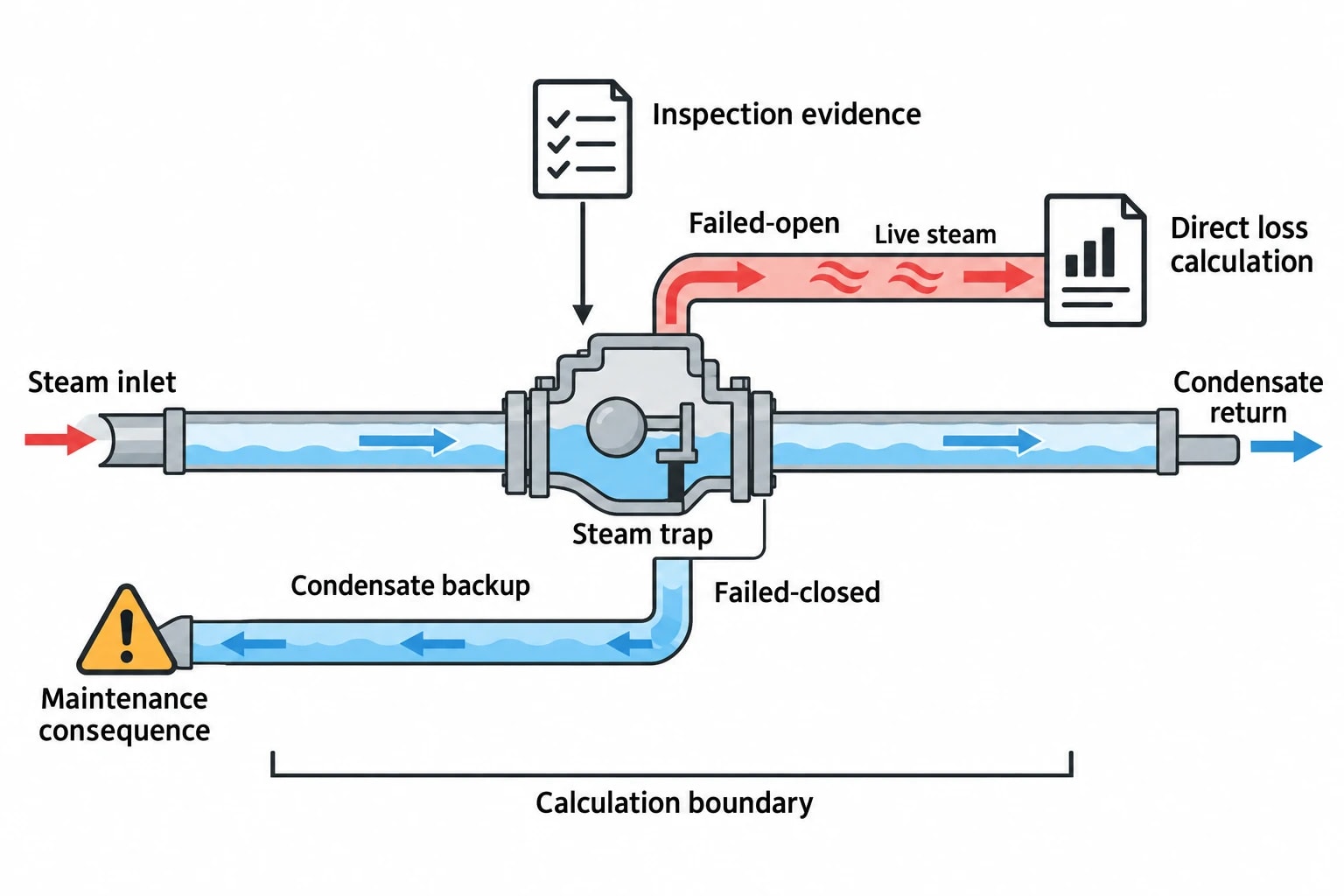
Steam traps should discharge condensate and non-condensable gases while retaining live steam. A failed-open trap passes live steam into the condensate system or atmosphere. A failed-closed trap backs condensate into the equipment it serves, reducing heat transfer and potentially creating water hammer.
Only the failed-open condition represents a direct live-steam-loss calculation. A failed-closed trap may still demand urgent action, but its maintenance case should rest on process, reliability and safety consequences rather than a presumed steam-loss rate.
The US Department of Energy identifies failed-open traps and partially leaking traps as separate conditions. The audit record should make that distinction. A trap recorded merely as “failed” offers too little information to support a credible calculation.
Establish the test boundary
Each steam trap loss calculation should identify where the calculation begins and ends. The minimum record should include:
- Trap tag, location, service and process area.
- Trap type, manufacturer and model where known.
- Nominal seat or orifice diameter, or a documented equivalent flow area.
- Upstream steam pressure at the time of inspection.
- Downstream pressure at the trap discharge or condensate return.
- Steam condition, including saturated or superheated service.
- Failure condition, inspection evidence and inspector confidence.
- Operating hours during which the loss can occur.
- Calculation method, assumptions and date.
This record gives maintenance, utilities and finance teams the same basis for review. It also prevents a surveyor from applying a full-bore atmospheric-leak estimate to a trap discharging into a pressurised condensate return.
Diagnose before calculating
Field diagnosis should use more than one observation. Acoustic monitoring can identify a continuous high-frequency signature, but live steam and flash steam can sound similar. Temperature data add context, yet trap type and saturation temperature must be understood before interpreting a surface reading.
A sound audit combines available evidence:
| Evidence | What it can establish | Limitation |
|---|---|---|
| Ultrasonic inspection | Continuous or intermittent discharge behaviour | Flash steam and plant noise can complicate interpretation |
| Temperature measurement | Whether temperatures align with expected steam and condensate conditions | Surface temperature alone does not prove live-steam leakage |
| Visual discharge test | Visible abnormal discharge where safe test points exist | Flash steam can appear during normal condensate discharge |
| Trap model and seat data | Likely available flow area and normal operating behaviour | Manufacturer data may be unavailable for legacy installations |
| Pressure measurements | Actual pressure differential across the trap | One reading may not represent variable operating conditions |
The Department of Energy recommends combining investigation methods because no single field technique delivers a perfect diagnosis. This is particularly important for thermodynamic and thermostatic traps, whose normal discharge patterns differ from float and inverted-bucket designs.
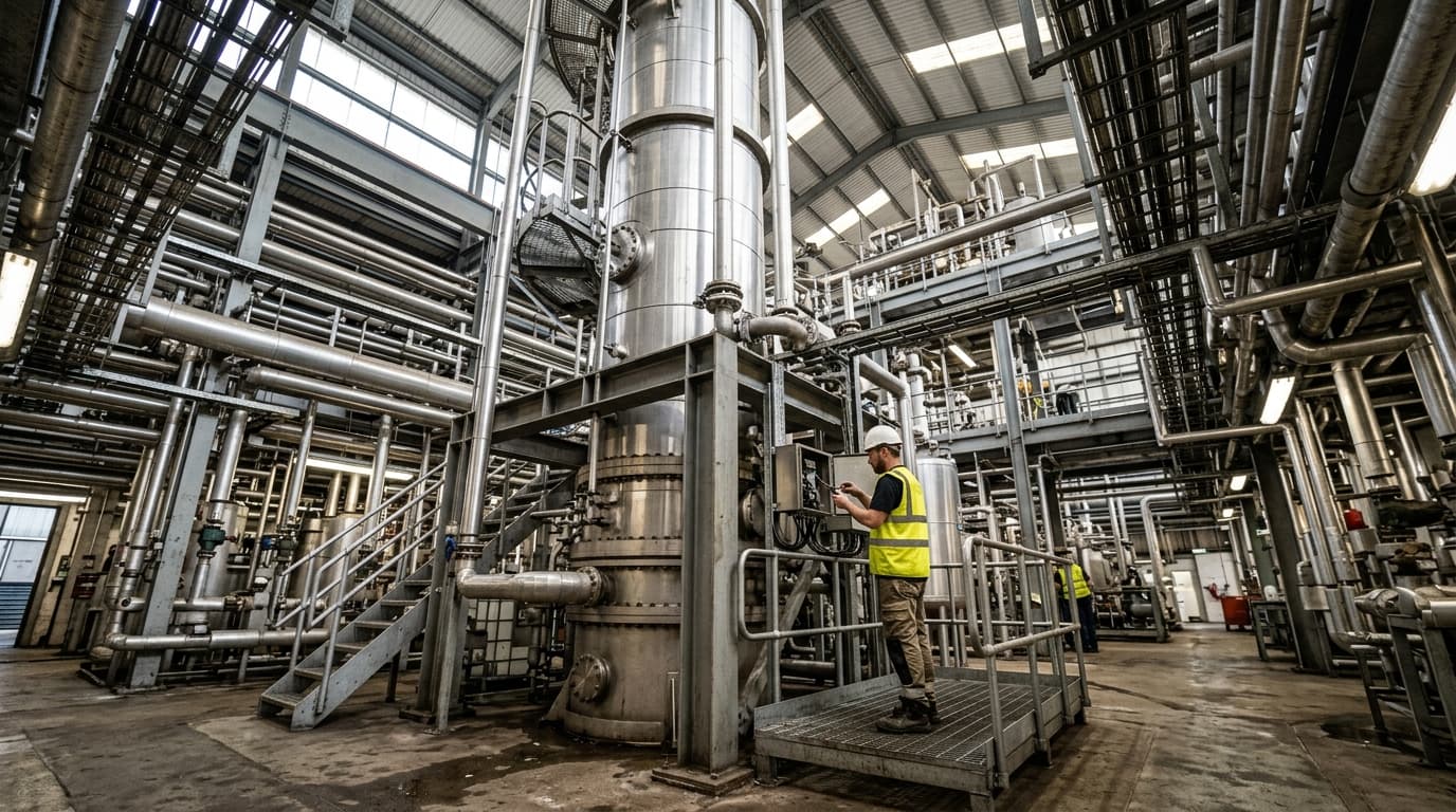
Omni Vision delivers turnkey utility metering, CO2 tracking, and AI-powered production KPI intelligence — giving you real-time dashboards and actionable insights across your entire facility.
Applying ASME PTC 39 to steam trap loss calculation
ASME PTC 39 is the applicable performance-test reference for steam traps. A field steam-trap programme should retain the same discipline: record the stated conditions, identify the equipment, and distinguish observed behaviour from calculated inference.
The calculation should be classified clearly.
Use three calculation confidence levels
A practical steam trap loss calculation methodology benefits from three confidence levels.
| Confidence level | Evidence basis | Appropriate use |
|---|---|---|
| Screening estimate | Trap condition and opening size are uncertain | Survey prioritisation and follow-up planning |
| Engineering estimate | Trap type, opening assumption, pressures and duty are documented | Maintenance budget justification |
| Verified loss | Direct flow measurement or controlled test confirms the rate | Savings validation and formal reporting |
An ultrasonic diagnosis can support a screening estimate. It does not establish a measured mass-flow rate. A documented trap seat diameter and pressure measurement can support an engineering estimate, provided the report states whether the opening is assumed to be fully available, partially obstructed or equivalent to another flow path.
Account for upstream and downstream pressure
Engineers must use absolute pressure in steam-flow relationships. A line operating at 7 bar g has an upstream absolute pressure of approximately 8 bar a. The discharge side also requires measurement or a justified assumption.
A trap discharging to atmosphere can have a large pressure drop. A trap discharging to a pressurised condensate return may have a much smaller differential pressure. That difference changes the flow calculation and can invalidate an atmospheric-discharge assumption.
For saturated steam, critical flow occurs when the pressure drop exceeds 42% of upstream absolute pressure, equivalent to downstream pressure below 58% of upstream absolute pressure. Under critical flow, reducing downstream pressure further does not increase mass flow through the restriction.
A 7 bar g steam supply discharging to atmosphere meets that condition. A trap discharging from 8 bar a into a 5 bar a condensate return does not. The latter case needs a pressure-dependent flow method or manufacturer-supported calculation rather than a critical-flow shortcut.
Calculating live-steam loss through a known opening
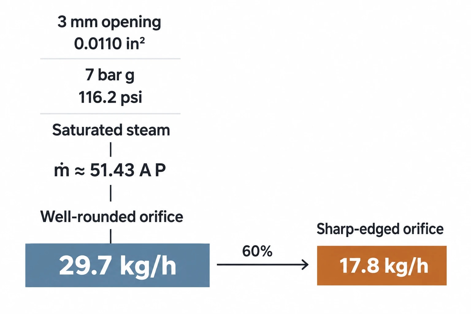
Napier’s equation is a recognised empirical relationship for estimating saturated-steam flow through an orifice. The US Department of Energy presents it in imperial units as:
m˙≈51.43APHere, m˙ is mass flow in lbm/h, A is the orifice area in square inches, and P is upstream absolute pressure in psi.
The Department of Energy limits this relationship to saturated steam through a well-rounded converging orifice. It also states that a sharp-edged orifice produces approximately 60% of the well-rounded-orifice result. The relationship provides a defined reference calculation, not a universal representation of every failed steam trap.
Worked steam trap loss calculation example
Consider a trap with a documented 3 mm circular opening, supplied with saturated steam at 7 bar g and discharging to atmosphere. The 3 mm diameter corresponds to an opening area of about 0.0110 square inches. The upstream absolute pressure is about 116.2 psi.
Napier’s equation gives a theoretical well-rounded-orifice loss of approximately 29.7 kg/h. Applying the Department of Energy’s sharp-edged-orifice guidance produces a corresponding estimate of about 17.8 kg/h.
This is a useful engineering range only if inspection confirms continuous live-steam blow-through and the full opening is available. The calculation should not be assigned automatically to a damaged trap.
A real failed trap may pass less steam because of:
- Partial seat obstruction.
- Condensate moving through the trap with steam.
- Variable inlet pressure.
- Pressurised condensate return conditions.
- Trap passages that do not behave as a single circular orifice.
- Intermittent rather than continuous leakage.
The US Department of Energy notes that an individual trap-loss estimate may fall between 10% and 100% of a theoretical value after these effects are considered. This range is a reason to state assumptions plainly and avoid false precision in annual savings reports.
Use manufacturer data where it is available
A trap manufacturer’s capacity information, valve coefficient or equivalent-flow-area method may represent a particular model better than a generic opening calculation. The audit should retain the manufacturer document, trap model and operating differential pressure alongside the resulting estimate.
Thermodynamic traps require particular care because flow can pass through several internal paths rather than one simple seat. Thermostatic traps may fail with the valve partially obstructing the opening. Inverted-bucket traps can present a different failure geometry.
The calculation record should identify the basis as one of the following:
- Measured seat orifice area.
- Manufacturer-supported equivalent flow area.
- Documented proxy from a matching trap model.
- Assumed partial-opening fraction.
- Direct measurement.
A screening estimate based on an unknown opening should trigger further investigation before it becomes the basis for major capital or shutdown decisions.
Annualising steam loss and valuing the maintenance opportunity
A loss rate in kg/h becomes meaningful when matched to the hours during which the trap can leak. Engineers should use actual operating records, line schedules and isolation periods rather than a default 8,760 hours.
The well-rounded-orifice example above would lose approximately 178.2 tonnes of steam per year at 6,000 leaking hours. The sharp-edged-orifice estimate would equate to about 106.8 tonnes per year over the same period.
Match the annual hours to the failure condition
A high-pressure utility header may remain live across most of the year. A clean-in-place branch, steriliser leg or seasonal food-processing line may operate only during defined campaigns. The annualisation should reflect the failure condition itself.
For intermittent discharge, the inspector should establish the proportion of operating time associated with abnormal live-steam passage. A trap that opens abnormally for 15 minutes in each hour should not receive the same annual loss figure as a confirmed continuous blow-through failure.
The record should state whether annual hours represent:
- Continuous exposure while the steam system is live.
- Production operating hours.
- Campaign or batch-schedule hours.
- Logged abnormal-discharge duration.
- A conservative planning assumption.
Value steam at the boiler boundary
The financial value should use an approved marginal steam cost in £/tonne. That value can include fuel, boiler efficiency, make-up water, water treatment, blowdown and applicable auxiliary-electricity costs where the site includes them in its steam-cost method.
Multiplying annual steam loss by the approved £/tonne steam cost provides an auditable maintenance value. This is preferable to converting steam mass directly into retail gas spend because boiler efficiency, condensate return, feedwater temperature and boiler operating pressure affect the cost of delivered steam.
The calculation should also separate live-steam leakage from flash steam. Flash steam produced during normal condensate pressure reduction is not evidence of failed-trap blow-through. Where flash steam is recovered and used at lower pressure, its recovered value should remain outside the failed-trap savings claim.
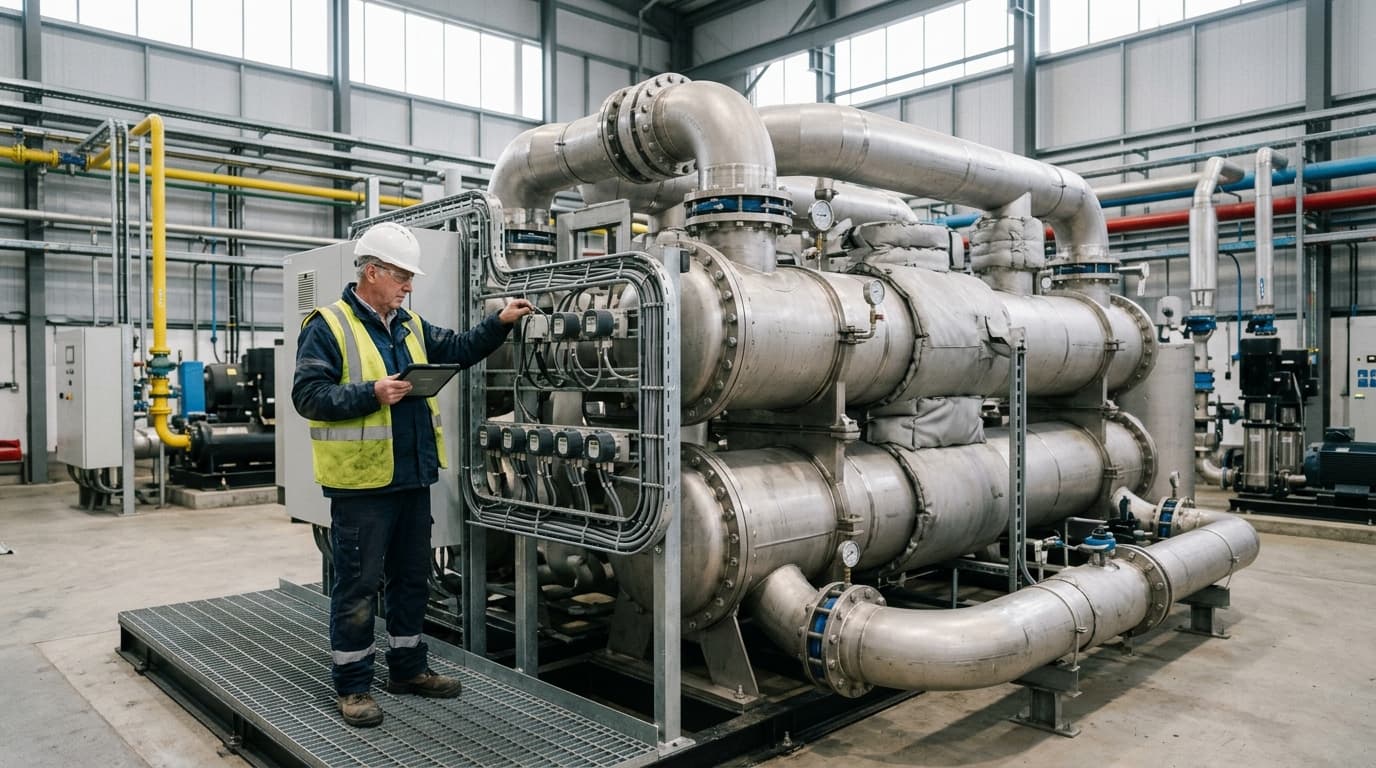
Track energy consumption, emissions, and process parameters with seamless PLC/SCADA integration via Modbus, OPC-UA, and MQTT protocols.
ISO 50001 measurement and verification for steam trap losses
ISO 50001:2018 provides an energy-management framework built around energy performance, data, measurement and continual improvement. It does not prescribe a steam-trap loss formula. A disciplined trap register supports the standard by making distribution losses visible within the steam energy baseline.
Include confirmed trap losses in the steam baseline
A baseline should distinguish legitimate process steam demand from persistent distribution loss. A confirmed failed-open trap may appear as excess steam demand during idle hours, stable utility operation or an unchanged production programme.
The baseline record should retain:
- Meter boundary and steam pressure level.
- Baseline period and reporting period.
- Relevant operating variables, such as production hours and weather where applicable.
- Known failed-open traps and their estimated live-steam loss.
- Repair dates and post-repair inspection results.
Energy performance indicators can be expressed as total steam use, steam use per production unit, or a model that accounts for relevant variables. For steam-trap work, the same meter boundary, production conditions and normalisation logic must apply before and after repair.
Verify repair savings through measurement and verification
A follow-up survey confirms that the repaired trap returns to expected condensate-discharge behaviour. Meter data can then test whether the expected reduction appears at the relevant steam boundary.
A practical measurement and verification sequence is:
- Record the pre-repair failure diagnosis, pressure conditions and calculated kg/h range.
- Record the repair date, work order and replacement trap details.
- Reinspect the trap under representative operating conditions.
- Select a post-repair period with comparable operating conditions.
- Compare actual steam use with expected steam use after accounting for relevant variables.
- Record whether the estimated saving was verified, revised or rejected.
This process prevents a site from claiming full theoretical savings where another operating change explains the reduction. It also identifies trap repairs whose meter-level impact is too small to isolate from normal steam-demand variation.
Prioritising repairs with a weighted decision matrix
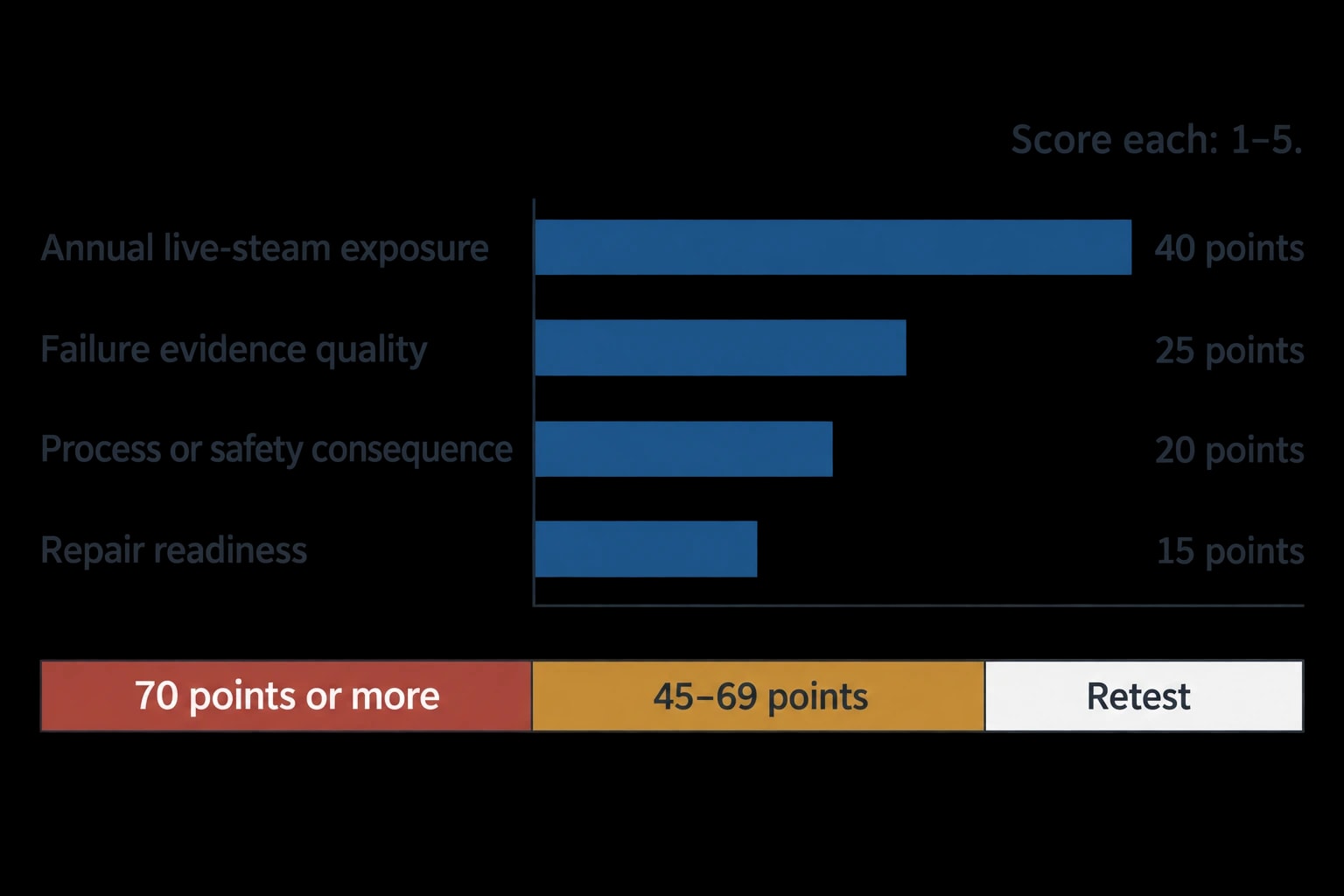
A weighted decision matrix gives maintenance teams a repeatable method for ranking steam-trap work. ASME PTC 39 does not prescribe a site maintenance-priority score, so each organisation should document its chosen criteria, thresholds and review process.
The following 100-point matrix provides a starting point.
| Criterion | Weight | Score thresholds |
|---|---|---|
| Annual live-steam exposure | 40 | 5 for at least 100 tonnes/year, 4 for 25 to under 100, 3 for 10 to under 25, 2 for 1 to under 10, 1 for under 1 tonne/year |
| Failure evidence quality | 25 | 5 for continuous live-steam failure confirmed by two methods, 3 for one strong indicator, 1 for uncertain diagnosis |
| Process or safety consequence | 20 | 5 where water hammer, unsafe discharge or confirmed process risk exists, 3 for material reliability exposure, 1 for energy loss alone |
| Repair readiness | 15 | 5 for safe repair in the current window, 3 where planned access is required, 1 where an extended shutdown is needed |
Score each criterion from 1 to 5, apply its weighting, and retain the individual scores with the trap record. A total of 70 points or more can trigger repair in the current maintenance window. A score of 45 to 69 can enter the planned work queue. A lower score should prompt a retest, improved pressure data or opening-size confirmation before committing resources.
Safety concerns override the numerical ranking. The matrix organises energy and maintenance work after the site has met its safety obligations.
Building an auditable steam trap loss register
A useful steam-trap register is more than a fault list. It connects physical inspection, calculation, operating hours, annual exposure and repair verification.
Each entry should retain the original estimate rather than overwrite it after repair. This allows the site to compare predicted and verified savings, improve assumed opening fractions, and identify trap types or process areas that produce repeated losses.
This article reflects the independent analysis and editorial opinion of EnerTherm Engineering. Product names, trademarks, and brands mentioned belong to their respective owners. EnerTherm Engineering is not affiliated with, endorsed by, or a licensee of any third-party software or product mentioned unless explicitly stated.

Technical Manager — EnerTherm Engineering
John Naranjo is Technical Manager at EnerTherm Engineering, bringing specialist expertise in chemical and environmental engineering. He recently led the implementation of Omni Vision, EnerTherm's real-time energy and utility monitoring platform. He holds an MSc in Environmental Engineering from the University of Huelva and a BSc in Chemical Engineering, with memberships in both the Energy Institute and IChemE.
