
PLC Energy Monitoring Integration Without PLC Write Access
OPC-UA and Modbus TCP provide sub-second reads without changing validated PLC code.
PLC energy monitoring integration extracts energy, utility and production-context data from programmable logic controllers and connected meters without creating a command path that could alter PLC logic, setpoints, safety functions or machine operation.
A pharmaceutical filling line can produce a sharp electrical peak as heaters, conveyors and compressed-air demand start together. Monthly billing data will not isolate that event. Read-only access to relevant meters and PLC status tags can show its timing, duration and production context without changing the validated control application.
Process plants need granular energy data for cost control, carbon reporting and operational improvement. They must also protect uptime, machine warranties and quality-system evidence. PLC energy monitoring integration should observe approved values only, with the control system retaining sole authority over the process.
In Siemens, Rockwell and Schneider Electric environments, the practical model is straightforward: collect utility measurements from meters and process context from selected PLC tags, then send the data to a monitoring platform through a separate collection layer. The collection layer does not write recipes, reset alarms, issue commands or modify a sequence programme.
Why PLC Energy Monitoring Integration Should Exclude Write Access
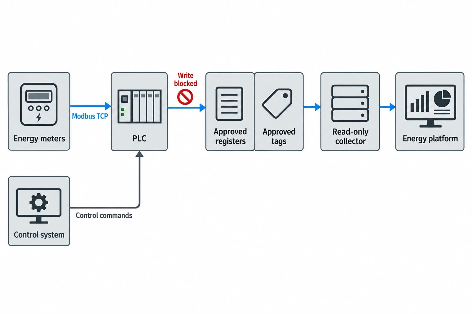
A PLC executes the logic that keeps production equipment running safely and repeatably. It handles interlocks, sequencing, alarm behaviour and process commands at defined scan intervals. Energy monitoring is a secondary workload.
A no-write architecture creates a clear operational boundary. The monitoring application can retrieve agreed values but cannot change them.
Protect PLC availability and machine ownership
A write-capable interface creates avoidable operational risk. A mistaken address, unsuitable client configuration or unauthorised action can affect values that control equipment behaviour. Exposing a command-capable route also enlarges the scope that controls teams must assess and manage.
The integration should expose only the points required for energy analysis, such as meter totals, real-time demand, machine state, batch identifier and production count.
The controls team should define the boundary in the design. The specification needs to identify:
- Approved PLC tags and meter registers.
- The source device and source address for each point.
- Data type, engineering unit, scaling and expected update rate.
- The permitted operation for each point: read only.
- The owner responsible for approving changes to the tag list.
This respects machine ownership. A monitoring project can proceed without altering the OEM programme or adding a functional dependency to production control.
Keep safety functions outside the monitoring scope
Safety instrumented functions, emergency stops, permissive logic and critical alarm actions should not form part of an energy-monitoring command path. In most projects, they do not need monitoring.
A machine-run state, production-active flag or non-safety equipment status may provide sufficient context for energy analysis. Where a site needs to view a safety-related status, the system owner should assess the read-only exposure separately and document the decision.
The platform should never become a control layer. Operations teams retain established procedures for responding to findings, including changing a start-up sequence, repairing a compressed-air leak or adjusting a boiler operating schedule.

Omni Vision delivers turnkey utility metering, CO2 tracking, and AI-powered production KPI intelligence — giving you real-time dashboards and actionable insights across your entire facility.
Select the Right Energy and Production Data
Useful monitoring begins with a measurement plan, not a broad request for every available PLC tag. A plant can collect thousands of values and still struggle to explain a demand peak if it lacks the right meter location or production-state signal.
Use meters for consumption and PLCs for context
Meters should provide the primary measurement of energy and utilities. PLC tags explain the operating state associated with consumption.
| Data group | Typical signals | Main use |
|---|---|---|
| Electricity | kWh, kW, current, voltage, power factor | Demand peaks, baseload and equipment consumption |
| Gas and oil | Volume, flow, energy total | Boiler and thermal-process fuel use |
| Steam | Mass flow, pressure, temperature, condensate flow | Process allocation and boiler performance review |
| Compressed air | Flow, pressure, compressor status | Leak investigation and off-shift demand |
| Water | Flow and total volume | Cleaning, process and site-consumption analysis |
| Production context | Batch ID, product code, run state, count, run time | Energy per batch, energy per tonne and idle-energy analysis |
A packaging line illustrates the split. A sub-meter measures electrical load, while a PLC state tag identifies whether the line was producing, cleaning, waiting for material or stopped by a fault. Combining those values reveals idle consumption that a site total cannot show.
Treat counters and live values differently
A cumulative kWh totaliser and a live kW reading serve different purposes. The totaliser supports consumption calculations and reconciliation. The live value supports demand analysis, peak investigation and trend review.
The integration design should state how it handles:
- Meter rollover.
- Meter reset after maintenance.
- Meter replacement.
- Communications gaps.
- Changes to scaling factors.
- Values outside a plausible operating range.
A collector that subtracts successive kWh totals without accounting for a reset can create a false consumption spike. Treating a live kW value as cumulative consumption can create an equally misleading report. These data-engineering issues directly affect the credibility of energy decisions.
Build a controlled tag and register list
The tag list is the working contract between operations, automation, energy and quality teams. Each entry should record the source, description, unit, data type, refresh expectation, intended use and owner.
For Modbus devices, the list should include the documented register address, register length, byte order and scaling. For OPC UA, it should include the node identifier, browse name and exposed data type. A controlled list prevents technicians from relying on informal spreadsheets or unverified memory locations when equipment changes.
Where a specified sub-meter is available, it should measure the energy value. PLC-derived calculations can support context or cross-checking, but should not replace direct measurement without documented engineering justification.
Maintain GAMP 5 Integrity in Pharmaceutical Facilities
In a pharmaceutical plant, a PLC may sit within a wider GxP-relevant environment. ISPE’s GAMP 5 Guide, Second Edition, sets out a risk-based approach for computerised systems used in regulated operations. The issue is not simply whether data can be read; it is whether the implementation preserves intended use, data integrity and the site’s validation evidence.
Define a separate monitoring boundary
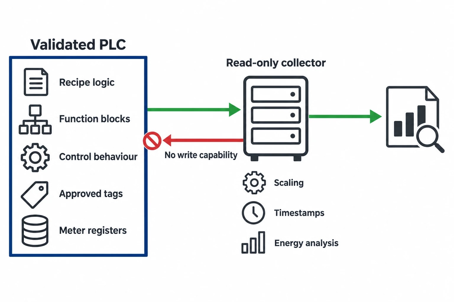
A read-only collector does not remove the need for change control or validation assessment, but it narrows the impact assessment. The approved PLC programme, recipe logic, function blocks and control behaviour remain outside the monitoring platform’s control boundary.
The assessment should describe what the collection layer does and does not do. It retrieves specified data, applies documented scaling where needed, timestamps values and presents them for energy and environmental analysis. It does not alter process parameters or execute PLC methods.
This gives quality and automation teams a clearer basis for deciding testing effort. The project can focus on data accuracy, availability, traceability and confirmation that the collector has no write capability.
Assemble evidence that stands up to review
A read-only claim needs testable evidence. The commissioning package should include:
- An approved tag list or meter register map.
- Evidence of the account or interface permissions used for collection.
- A test showing that disallowed write operations are rejected.
- Records of source time, collection time, units and scaling.
- Test results for connection loss, restart and recovery.
- A documented treatment for stale, missing and implausible values.
- Change-control records for added points, altered scaling or replaced devices.
This produces an auditable integration design where batch records, quality investigations or energy reports depend on the reported data.
Protocol Choices for Read-Only PLC Data Extraction
Protocol selection depends on the installed PLC, meter capability, firmware, licences, available interfaces and the site’s approved integration methods. The protocol does not guarantee a read-only outcome. Server configuration, user permissions and tag scope create that outcome.
OPC UA for structured PLC energy data
OPC Unified Architecture, or OPC UA, provides a structured client-server method for industrial data exchange. Its information model allows variables to advertise access characteristics, including whether a current value is readable or writable. User-specific access rights can impose further restrictions.
An OPC UA server can expose a limited namespace containing electricity demand, utility totals, equipment run state, batch identifier and production count. The monitoring client reads those approved nodes only.
OPC UA subscriptions and monitored items can reduce repeated requests for unchanged values. The OPC Foundation specifies that a server revises the requested sampling interval to one it supports. Engineers should record the agreed interval and test actual behaviour rather than assuming a requested rate will be delivered unchanged.
Modbus TCP for utility meters and skids
Modbus TCP remains widespread in electrical meters, flow meters, compressor controls and utility skids. The Modbus Application Protocol defines separate function codes for reading coils, discrete inputs, holding registers and input registers, alongside functions capable of writing values.
A collector should request only documented read functions and the registers required by the measurement plan. The device register map must confirm byte order, register width, signed or unsigned representation, scaling and the meaning of each totaliser.
Reading contiguous registers in sensible blocks can reduce communications overhead and simplify troubleshooting. Large, indiscriminate scans of a meter register map add data with no defined analytical purpose.
BACnet and MQTT where they fit
BACnet can supply utility and environmental values from building-services equipment, plant rooms and support areas. A defined list of read properties can bring those values into the same energy record as production utilities.
MQTT serves a different role. A local gateway can publish approved PLC and meter readings to the monitoring platform, avoiding the need for the platform to query each field device directly. The integration team must still define the payload, units, timestamps and quality status.
Neither protocol replaces the measurement plan. They transport data that the engineering team has already selected and defined.

Track energy consumption, emissions, and process parameters with seamless PLC/SCADA integration via Modbus, OPC-UA, and MQTT protocols.
Capture Fast Energy Events Without Burdening PLC Scan Cycles
Sub-second data can help a facility investigate rapid changes in electrical demand. Heater banks, large motors, variable-speed drives, compressors and batch transitions can produce short events that disappear in 15-minute utility data.
Fast measurement belongs in the power meter or power-quality instrument.
Let the meter capture the transient
A PLC is a control device, not a high-speed energy recorder. Polling a busy PLC for a long list of scattered values at aggressive intervals can add communications load without improving the underlying measurement.
A suitable electricity meter can capture high-resolution demand values, interval data or event records. The integration layer retrieves that evidence at an interval that fits the meter capability and investigation need. The PLC supplies the associated process marker, such as a heater-enable state, compressor-start status or batch-transfer status.
The meter identifies the magnitude and timing of the electrical event, while the PLC explains what the equipment was doing at that time.
Set an evidence-based sampling rate
There is no universal polling interval for energy monitoring. ISO 50001:2018 requires organisations to use data to understand, measure and improve energy performance, including through energy performance indicators and energy baselines. It does not prescribe a single data-collection interval.
The interval should reflect the energy use under review:
- Slow-moving utility totals may need only periodic collection.
- Equipment run state may need a rate sufficient to identify production and idle periods.
- Live demand may need a faster interval during a peak-demand study.
- Sub-second events require a meter that records at that resolution.
An OPC UA monitored item also has a negotiated sampling interval, which the server may revise to its supported rate. The engineering record should retain the requested rate, actual supported rate, data source update rate and any local aggregation applied before storage.
Test under real operating conditions
Bench testing does not prove that an integration will behave acceptably during a shift change, batch transition or simultaneous equipment start. Commissioning should test the final point list at the intended collection rate while the plant operates normally.
The test should confirm response behaviour, data gaps, source timestamps and the effect on the PLC’s normal communications. Where the meter provides a local display or historian, compare its readings with the collected record over an agreed period.
Turn PLC and Meter Values Into Audit-Ready Energy Data
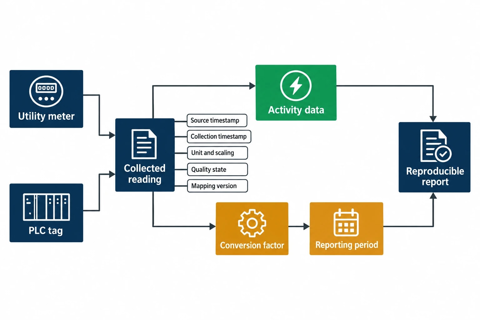
Data becomes useful when a facility can trace a reported result back to its source. A site total may reconcile with a utility bill, but cannot explain which line, batch or operating state drove the result.
Preserve source context and data quality
Each collected value should retain:
- Source device and tag or register identifier.
- Source timestamp where available.
- Collection timestamp.
- Engineering unit and scaling version.
- Quality state, such as received, stale, unavailable or substituted.
- Configuration version for the tag mapping.
This makes later investigation possible. If a steam total changes after a meter replacement, the platform should show when the source changed and whether its scaling changed with it.
For electricity, gas and fuel data, physical consumption should remain separate from emissions factors. Metered kWh, volume or mass are activity data. The applied conversion factor, reporting period and calculation method are controlled reporting inputs. This separation allows a facility to reproduce a prior report when the Department for Energy Security and Net Zero publishes updated annual conversion factors.
Support ISO 50001, ESOS and SECR work
ISO 50001:2018 uses energy performance indicators and baselines to support continual improvement. Production-linked data strengthens those measures because it distinguishes useful energy from consumption during waiting, cleaning or downtime.
UK ESOS guidance requires energy audits to rely, so far as reasonably practicable, on verifiable energy-consumption data measured over a 12-month period. Granular meter data does not replace the audit process, but provides a stronger factual base for identifying significant energy uses and assessing improvement opportunities.
For Streamlined Energy and Carbon Reporting, reliable activity data supports the calculation and reporting of energy use and associated Scope 1 and Scope 2 emissions. The annual UK government conversion factors support reporting based on activity data, including purchased electricity and fuel consumption.
Commission PLC Energy Monitoring Integration With Clear Acceptance Tests
A successful project needs acceptance criteria that automation, operations, quality and energy teams can inspect.
Before connection
Confirm the PLC type, available interface, meter capability, approved tag or register list and equipment owner. Identify the values required for energy analysis, then remove points with no defined use.
Review units, scaling, totaliser behaviour and source time. Agree the expected collection interval for each data group before configuration begins.
During commissioning
Create the minimum read-only access required for the agreed points. Verify that the collector can retrieve intended values and that unauthorised write operations are refused.
Compare meter totals with local displays and utility records across an agreed operating period. Test connection interruption, collector restart, PLC restart and recovery from a missed reading. Record how the system labels unavailable or stale data.
At handover
Place the tag list, protocol configuration, network drawing, test evidence and configuration backup under document control. Assign owners for meter replacement, tag additions, scaling changes and data-quality review.
Omni Vision applies this read-only integration model to bring metered utility consumption and approved production context into one energy and environmental record. Engineers gain the data needed to investigate energy performance while the PLC remains responsible for running the plant.
This article reflects the independent analysis and editorial opinion of EnerTherm Engineering. Product names, trademarks, and brands mentioned belong to their respective owners. EnerTherm Engineering is not affiliated with, endorsed by, or a licensee of any third-party software or product mentioned unless explicitly stated.

Technical Manager — EnerTherm Engineering
John Naranjo is Technical Manager at EnerTherm Engineering, bringing specialist expertise in chemical and environmental engineering. He recently led the implementation of Omni Vision, EnerTherm's real-time energy and utility monitoring platform. He holds an MSc in Environmental Engineering from the University of Huelva and a BSc in Chemical Engineering, with memberships in both the Energy Institute and IChemE.
