
The 7-Step Energy Audit Methodology for UK Factories
How 12 months of verified data expose energy losses and fund projects
An energy audit methodology for factories is a structured process for measuring how a manufacturing site buys, converts and uses energy, then turning that evidence into prioritised reduction projects. For UK organisations in ESOS Phase 3, the second progress update is due by 5 December 2026, making traceable savings evidence an operational requirement.
A factory audit needs more than a walk-through of lights, boilers and compressors. Metals, plastics, assembly and general manufacturing sites often combine electricity-intensive drives with compressed air, process heat, ventilation, extraction and variable production schedules. A credible audit separates productive energy use from avoidable losses while accounting for weather, operating hours, product mix and throughput.
EnerTherm Engineering’s seven-step methodology creates that structure. It aligns practical plant investigation with the energy-management principles in BS EN ISO 50001:2018, ISO 50002-1:2025 and ISO 50002-3:2025. The result is a defensible baseline, a clear improvement plan and investment cases for operations directors.
Step 1: Set the factory energy audit scope and decision criteria
Define the boundary before collecting readings
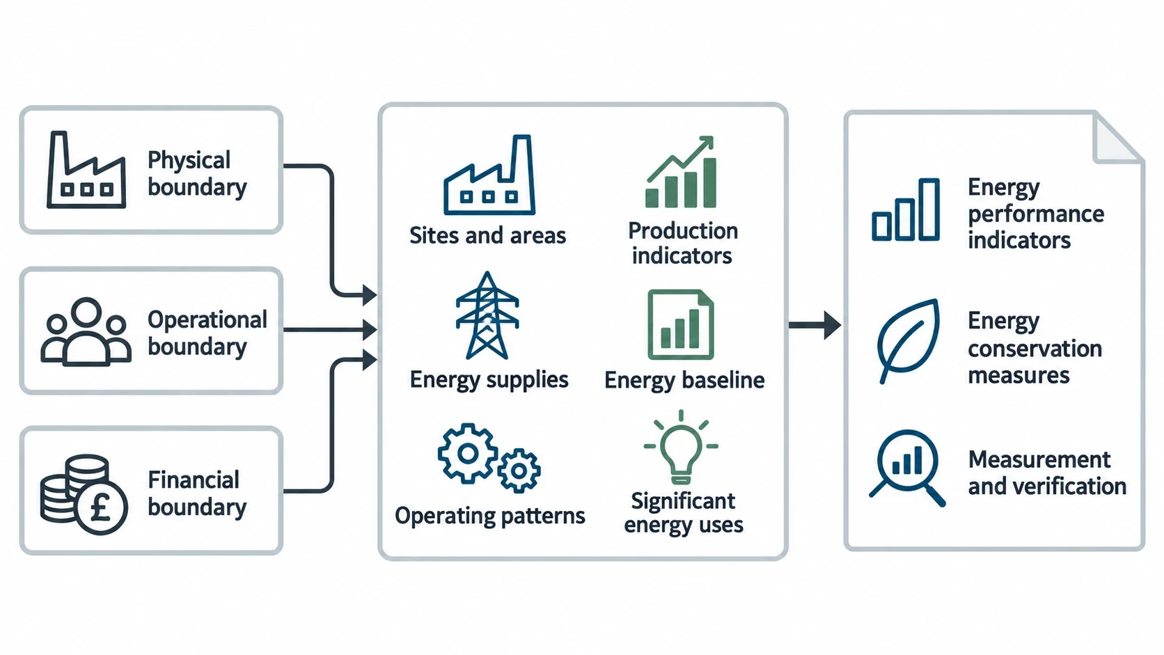
The audit team should agree the physical, operational and financial boundary at the outset. This prevents a common failure: measuring a utility system without establishing which lines, shifts, buildings, fuels or support services it serves.
The scope should identify:
- Sites, buildings and production areas included in the audit
- Electricity, gas, LPG, oil, compressed air, steam and other energy supplies
- Production processes, utility systems and support loads
- Operating patterns, including shutdowns, weekends and maintenance periods
- Relevant production indicators, such as tonnes produced, machine hours, batches or finished units
- Current energy costs, carbon reporting requirements and planned capital projects
For a multi-site manufacturer, ESOS requires site visits that represent the energy use of the assets and activities covered by the audit. The organisation must record why the selected sites are representative. A common production process may justify a smaller sample, while sites with different furnaces, compressors, operating hours or product mixes need closer examination.
Agree what a successful audit will deliver
An audit should finish with decisions, not a catalogue of observations. The audit brief should define the expected deliverables: an energy baseline, significant energy uses, energy performance indicators, a register of energy conservation measures, carbon-reduction estimates, capital requirements, project risks and a measurement and verification plan.
The work should also align with management priorities. A factory facing constrained electrical capacity may value demand reduction and load shifting. A site replacing an ageing boiler may need a heat-demand profile before selecting equipment. A business preparing its ESOS progress update needs a record of completed measures and substantiated savings.

Identify where your plant is losing energy and quantify the savings potential — our audits map every heat source, sink, and waste stream in your facility.
Step 2: Build a 12-month energy baseline for the factory
Reconcile utility bills, meter data and production records
A reliable baseline starts with at least 12 consecutive months of energy-consumption data. ESOS guidance requires verifiable data where reasonably practicable, with estimates documented where gaps remain. Bills establish total purchased energy, but interval data and sub-meter readings reveal when and where energy is consumed.
The audit team should reconcile invoices, half-hourly electricity data, gas records, fuel deliveries and internal meter logs. Differences need investigation. A missing meter channel, incorrect multiplier, estimated bill or unexplained change in consumption can distort a project case.
The baseline should distinguish fixed energy demand from production-related demand. A factory may consume substantial energy when production is stopped because compressors remain pressurised, extraction fans run continuously, heaters hold temperature or equipment is left in standby.
Identify significant energy uses
Significant energy uses are processes and systems that dominate consumption or offer material improvement potential. In many factories, the initial list includes:
- Process heating, ovens, furnaces, dryers and melting equipment
- Compressed-air generation and distribution
- Motors, pumps, fans, conveyors and hydraulic systems
- Refrigeration and cooling systems
- Extraction, make-up air and space heating
- Lighting, offices and welfare areas
ISO 50002-1:2025 provides the general audit framework, while ISO 50002-3:2025 focuses on process energy audits. Together, they support a factory-level view that connects energy input to the conditions that produce finished goods.
Energy-intensity indicators convert raw consumption into a useful operational measure. Suitable indicators vary by plant: kWh per tonne of steel processed, kWh per moulding cycle, gas consumed per batch, or compressed-air energy per production hour. The indicator should relate to a measurable activity driver and remain consistent over time.
Account for changing operating conditions
A baseline should not treat all months as identical. Production volume, product type, ambient temperature, scrap rate, shift pattern and planned downtime can materially affect energy use. The audit team should record these factors alongside energy data so that later savings claims compare like with like.
BS EN ISO 50001:2018 emphasises data collection, normalisation and performance evaluation. A factory should explain why its energy intensity changed rather than assume that lower monthly consumption represents improved performance.
Step 3: Plan non-intrusive monitoring and the site survey
Select measurements that answer a decision
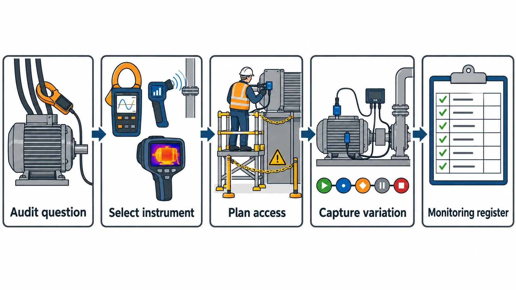
Instrumentation should be selected against specific questions. A clamp-on power analyser can establish whether a motor runs lightly loaded, cycles excessively or draws high power during idle periods. An ultrasonic leak detector can locate compressed-air leaks without stopping production. Thermal imaging can identify hot surfaces, insulation defects, overheated electrical connections and abnormal heat loss.
Useful survey equipment includes power analysers, portable flow meters, pressure loggers, temperature sensors, combustion analysers, ultrasonic leak detectors and thermal cameras. Measurements should capture enough operating variation to represent the process. A ten-minute power reading during a quiet shift rarely supports a capital decision.
For batch and shift-based factories, the monitoring plan should cover start-up, normal production, changeovers, idle periods and shutdown. For continuous operations, it should capture representative production rates and known process constraints.
Work safely around live industrial equipment
Energy auditing often involves live electrical panels, pressurised systems, hot process equipment and moving machinery. The site safety plan should define access permissions, isolation requirements, permit-to-work arrangements, personal protective equipment and limits on intrusive testing.
Non-intrusive monitoring reduces disruption, but it does not remove site risks. Plant engineers should confirm where instruments can be installed and ensure that temporary sensors do not interfere with guards, controls, maintenance access or product quality.
A monitoring register should record meter location, identifier, measurement units, sampling interval, installation date, removal date and known limitations. This makes the evidence usable during project design, commissioning and verification.
Step 4: Assess compressed air, motor drives and process heat
Find compressed-air waste before buying capacity
Compressed air is among the most expensive industrial utilities to generate. Carbon Trust manufacturing guidance states that leakage can reach 30% of generated compressed air at industrial sites. An ultrasonic survey should therefore form part of routine factory energy audit methodology.
The audit should locate and tag leaks, then estimate their significance using system pressure, leak characteristics and compressor operating patterns. Leak repair is only part of the assessment. Engineers should also review:
- Compressor discharge pressure and local pressure requirements
- Artificial demand caused by excessive pressure settings
- Inappropriate uses of compressed air for cooling, cleaning or agitation
- Compressor sequencing and unloaded running
- Receiver capacity and pressure stability
- Intake-air temperature and condition
- Distribution pipework, isolation valves and point-of-use regulators
A recurring leak-repair programme needs ownership. Each identified leak should have a location, repair action, responsible person, target date and confirmation test after repair. Otherwise, the losses return at the next survey.
Profile motors and identify variable-load duties
Motors drive many of the largest electrical loads in a factory, yet their behaviour often goes unmeasured. Power logging can show whether a fan, pump, conveyor or hydraulic power unit runs continuously, cycles against a closed valve, operates at reduced demand or remains energised while production is idle.
Variable speed drives can reduce energy use where process demand changes and the driven equipment suits speed control. The audit should establish the duty cycle and control method before recommending a drive. A poorly controlled fan may benefit from variable speed control, while a conveyor with a constant-speed process requirement may not.
The engineering case should also consider harmonics, cooling at reduced motor speed, process-control requirements, maintenance capability and product quality. A drive is part of a system change, not a generic efficiency add-on.
Analyse combustion and heat losses at process equipment
Process heat needs a combined review of combustion, temperature control, heat transfer and heat containment. For ovens, furnaces, dryers and thermal treatment equipment, the audit should examine firing patterns, excess air, flue-gas temperature, door openings, product loading, refractory condition, insulation and heat-recovery opportunities.
Combustion tuning can reduce avoidable fuel use where burners operate outside appropriate settings. Thermal imaging can identify degraded insulation, hot spots around doors and seals, and exposed high-temperature surfaces. The audit must distinguish a surface-temperature observation from a full heat-loss calculation. Equipment design, operating temperature, surface area and ambient conditions affect the case for insulation improvement.
For plastics processing, barrel heaters, mould-temperature control and drying equipment require close attention to production rate and material condition. For metals, furnace loading, holding time and extraction rates can dominate gas demand. The audit should follow the process rather than impose a generic checklist on every line.

Identify where your plant is losing energy and quantify the savings potential — our audits map every heat source, sink, and waste stream in your facility.
Step 5: Analyse profiles, establish causes and quantify opportunities
Turn readings into operational evidence
The analysis stage combines utility data, temporary measurements, production records and site observations. Load profiles should expose base loads, peaks, idle consumption and the relationship between output and energy demand.
An audit team should test the reason for each abnormal pattern with operations and maintenance staff. A weekend electricity load may arise from compressors, refrigeration, frost protection, extraction, IT equipment or a production constraint. The measure depends on the cause.
The energy baseline should record:
| Baseline element | Factory audit evidence |
|---|---|
| Energy supply | Electricity, gas and other fuel consumption by period |
| Significant energy uses | Process lines and utility systems that require priority attention |
| Activity drivers | Tonnes, batches, operating hours, units or machine time |
| Energy performance indicators | Consumption related to the selected activity drivers |
| Influencing factors | Product mix, weather, shift pattern, downtime and quality requirements |
| Baseline period | Defined 12-month period and any documented estimates |
Separate opportunity types
The audit should categorise measures by the intervention required. This gives plant management a balanced programme rather than an unfocused capital wish list.
Operational measures can include shutdown discipline, pressure-setpoint reduction, insulation maintenance, leak repair and revised equipment schedules. Control improvements may address compressor sequencing, boiler controls, fan speed control or temperature setpoints. Capital measures can include insulation upgrades, heat recovery, high-efficiency motors, variable speed drives or replacement process equipment.
Each opportunity should state the affected asset, proposed change, implementation constraint and evidence supporting the estimated saving. An unverified estimate is inadequate for a project approval paper or ESOS action-plan reporting.
Step 6: Prioritise factory energy conservation measures with investable cases
Rank projects by value, practicality and risk
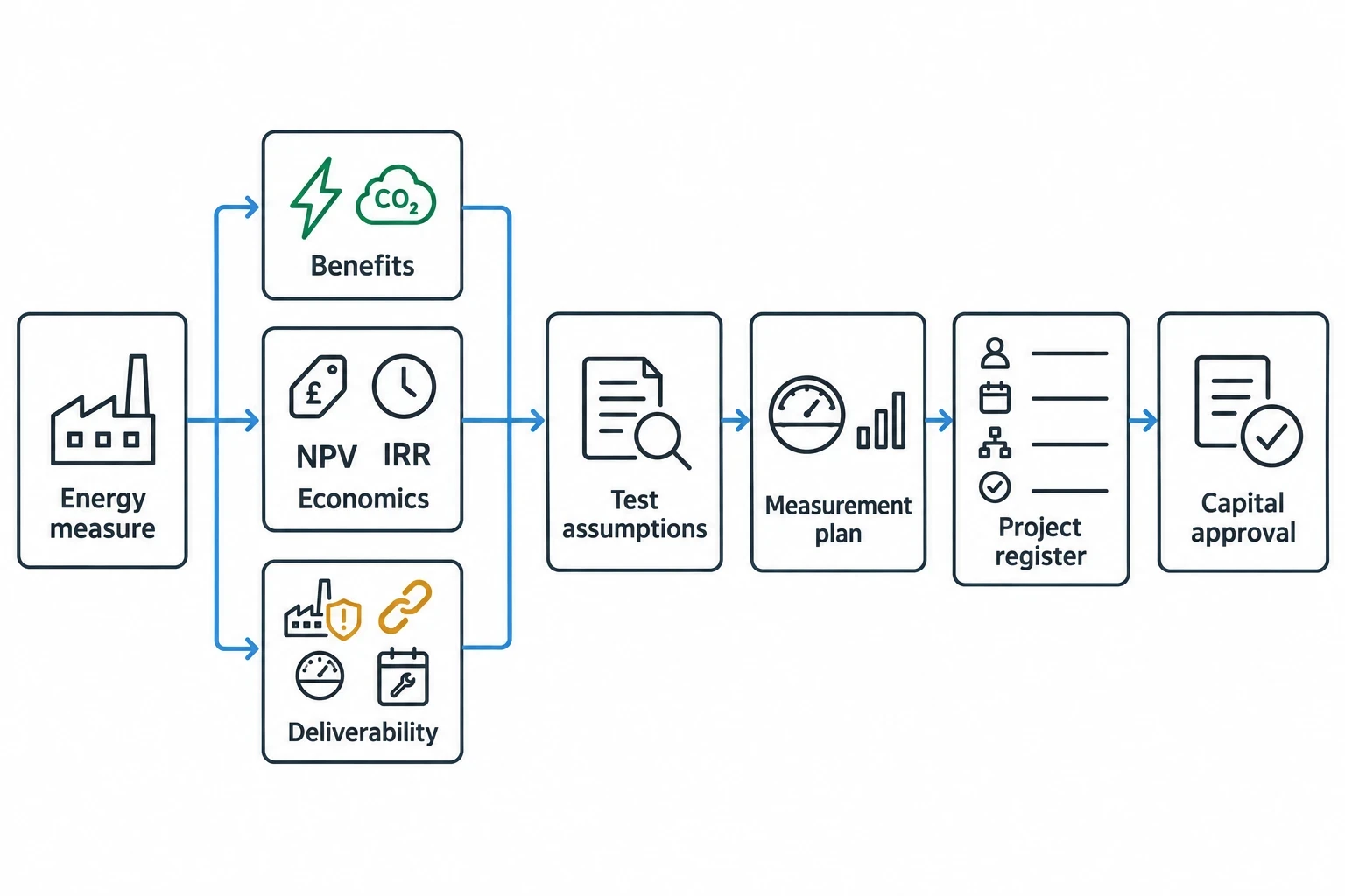
Payback matters, but it should not be the only ranking criterion. A short-payback project that requires repeated production stoppages may have a different priority from a larger heat-recovery project timed with a planned shutdown.
A practical prioritisation process assesses:
- Annual energy saving and expected carbon reduction
- Capital cost, maintenance cost and operating impact
- Simple payback, net present value and internal rate of return
- Production, quality, safety and maintenance risks
- Dependency on other projects or planned asset replacement
- Availability of meters for measurement and verification
- Delivery timing, including shutdown windows and vendor lead times
The audit report should state assumptions behind the financial case, including energy prices, operating hours, production volume and equipment availability. Decision-makers can then test the sensitivity of the project case rather than treat a single savings figure as certain.
Create a delivery programme, not a static report
The final project register should nominate an owner, target date, approval route and expected verification method for each measure. It should also identify projects that need further design work, trials or vendor quotations before capital approval.
Vendor selection should test technical compliance, operating range, maintainability, guarantee conditions, controls integration and commissioning support. The procurement process should require vendors to state performance assumptions clearly, particularly where energy savings depend on production duty, pressure, temperature or product throughput.
Step 7: Implement, commission and verify energy savings
Protect savings through commissioning
A completed installation does not prove an energy saving. Commissioning should confirm that equipment operates at intended setpoints, controls respond correctly, operators understand the revised procedure and maintenance teams receive appropriate handover information.
For compressed-air projects, this may include checking pressure stability, compressor sequencing and leak repairs after normal operation resumes. For motor-drive projects, it may include confirming minimum and maximum speeds, process-control response and motor temperatures. For process heat measures, commissioning should confirm combustion settings, temperature uniformity and product-quality performance.
Use measurement and verification to close the loop
The measurement and verification plan should be agreed before implementation. It should specify the baseline period, measurement boundary, energy meter, operating variables, adjustment method, reporting period and responsible owner.
IPMVP protocols provide a recognised structure for measurement and verification. The appropriate approach depends on the project. A sub-metered compressor upgrade may support equipment-level measurement, while a production-line improvement may require a whole-facility or process-area comparison adjusted for throughput and operating conditions.
The verified result should feed back into the energy baseline, project register and management review. This gives UK manufacturers evidence for ESOS progress reporting, ISO 50001 energy-performance review and investment decisions.
This article reflects the independent analysis and editorial opinion of EnerTherm Engineering. Product names, trademarks, and brands mentioned belong to their respective owners. EnerTherm Engineering is not affiliated with, endorsed by, or a licensee of any third-party software or product mentioned unless explicitly stated.

Simulation Engineer — EnerTherm Engineering
Rajesh Sekar is a Simulation Engineer at EnerTherm Engineering, specialising in computational fluid dynamics (CFD), finite element analysis (FEA), and thermal process simulation. He holds a degree from Cranfield University and brings extensive experience in simulation-based product development from the automotive, aerospace, and energy sectors.
