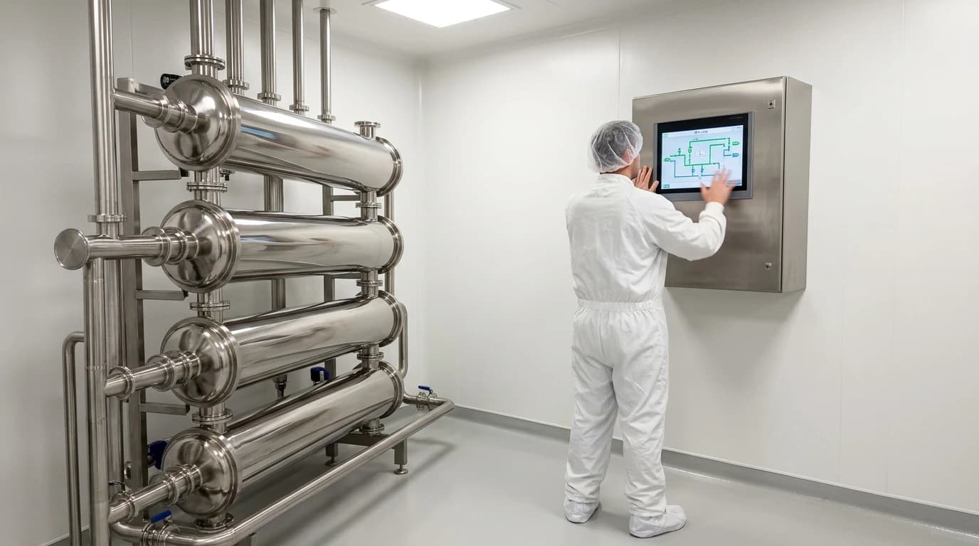
WFI Heat Recovery Using Double Tube Sheet Exchangers
Preventing contamination with double tube sheet designs when cooling WFI loops to 25°C.
Water for Injection (WFI) heat recovery is a thermal engineering process that reclaims energy from high-temperature sanitary water streams using double tube sheet heat exchangers to reduce steam and cooling water demands while maintaining strict sterility. Operating high-temperature WFI storage and distribution loops at 75°C to 80°C consumes up to 40 per cent of a typical UK biotech facility's thermal utility budget. Continuous circulation at these temperatures is necessary to prevent biofilm formation and ensure microbial suppression. However, when formulation and compounding processes require cold water (typically below 25°C), the water must be cooled at the point of use. Without an effective energy recovery system, this thermal cycle rejects massive amounts of heat to the facility's chilled water utility, only to require equivalent steam injection to reheat the loop.
Implementing energy-saving measures on these loops requires a detailed understanding of clean utility engineering, thermodynamic pinch points, and microbiological safety. The design must guarantee that the recovered energy does not come at the cost of sterile integrity.
Thermodynamic Foundations of WFI Loop Heat Recovery
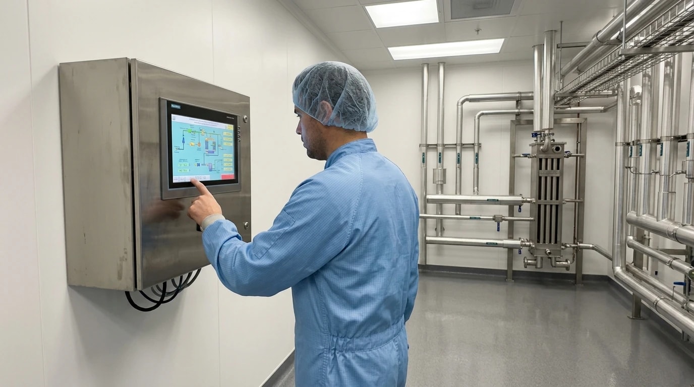
Thermal engineering in cleanrooms and sterile manufacturing environments differs substantially from standard industrial heating, ventilation, and air conditioning (HVAC) or process heating. Every thermal interface introduces a risk of contamination that could compromise an entire production run.
The Thermal Penalty of Hot Loop Circulation
In high-purity water loops, temperature control is the primary mechanism for microbial suppression. Biotech facilities distribute WFI through insulated networks above 75°C to self-sanitise the system, rapidly killing pathogens like Pseudomonas aeruginosa. However, when processes require ambient water, cooling this stream and subsequently reheating the return water creates an immense utility draw. Without heat recovery, the double penalty of chiller load and boiler steam significantly inflates operating costs.
Thermal Energy Recovery and the Pinch Point
Thermal design teams use Pinch Analysis to match these heating and cooling demands. This systematic methodology matches thermal energy sources (streams needing cooling) with thermal energy sinks (streams needing heating) across the facility. In a high-purity water network, the primary heat source is the hot WFI return stream, while the primary heat sink is the cold purified water feed entering the distillation system.
By mapping the mass flow rates and specific heat capacities of these streams, engineers plot composite curves to determine the optimum heat recovery temperature difference. This analysis identifies the exact thermodynamic bottleneck, or pinch point, of the utility network. Transferring heat directly across this boundary using a double tube sheet heat exchanger minimises the need for external boiler steam and cooling water, simultaneously lowering utility costs and carbon emissions.
The Barrier Requirement in Sanitary Environments
While recovering heat is economically attractive, process engineers cannot use standard, off-the-shelf plate or shell and tube heat exchangers. Standard thermal equipment presents a persistent risk of cross-contamination. If a standard exchanger develops a pinhole leak, the higher-pressure stream immediately infiltrates the lower-pressure stream. If utility cooling water leaks into a sterile WFI loop, the entire batch is ruined, resulting in millions of pounds in lost product and severe regulatory non-compliance under the Medicines and Healthcare products Regulatory Agency (MHRA).

Pinch analysis identifies the thermodynamic minimum energy requirement of your process — then designs the heat exchanger network to achieve it.
Why Double Tube Sheet Exchangers are Essential for WFI Loop Heat Recovery
A double tube sheet design represents the only industry-accepted method for recovering thermal energy directly from a WFI loop without violating sterile boundary regulations. The design introduces an absolute physical barrier between the sterile and non-sterile media.
The Double Tube Sheet Isolation Mechanism
To prevent cross-contamination between the WFI loop and the utility or service streams, heat exchangers must utilise a Double Tube Sheet (DTS) design. A DTS exchanger features two parallel tube sheets at each end of the tube bundle rather than a single shared plate. The inner tube sheet seals the sterile WFI flowing inside the tubes, while the outer tube sheet seals the heating or cooling medium flowing inside the shell.
The Physical Leakage Detection Chamber
The space between the two parallel tube sheets forms a physical leakage detection gap that is open to the atmosphere. If a tube joint on the shell side fails, the utility fluid leaks into this gap and drains away through a dedicated vent or drain line, preventing it from entering the product tubes. Similarly, if a tube joint on the product side fails, the sterile WFI leaks into the same gap. Because the two fluid streams are completely separated by this physical air space, cross-contamination is mechanically impossible.
Standard Conflations: The BS EN 12591 Bitumen Myth
When exploring standards for Water for Injection (WFI) heat recovery, search queries occasionally conflate terms like 'WFI loop heat recovery double tube sheet BS EN 12591'. However, a review of international standard databases shows that BS EN 12591 actually refers to 'Bitumen and bituminous binders — Specifications for paving grade bitumens'. This code has absolutely no relevance to clean utilities, sterile heat transfer, or high-purity water distribution.
To ensure regulatory compliance and mechanical integrity in UK facilities, utility engineers must instead design pressure equipment in accordance with the Pressure Equipment (Safety) Regulations 2016 (the UK transposition of the European Pressure Equipment Directive 2014/68/EU) and mechanical codes such as BS EN 13445 (for unfired pressure vessels) or ASME Section VIII Division 1. Adhering to these correct standards ensures that the high cyclic pressures and thermal expansion of a WFI system do not compromise the physical sanitary barriers.
The differences between conventional single tube sheet designs and double tube sheet safety designs dictate where each technology can be safely applied:
| Parameter | Single Tube Sheet (STS) Exchanger | Double Tube Sheet (DTS) Exchanger |
|---|---|---|
| Leakage Pathway | Direct cross-contamination between circuits | Gravity drainage to external leak chamber |
| Structural Barrier | Single metal barrier (joint/wall) | Dual metal barriers separated by an air gap |
| Leakage Visibility | Hidden inside the process stream | Visible external drip or atmospheric vent |
| Recommended Use | Low-risk utilities (glycol, non-sterile water) | High-purity clean utilities (WFI, PW, pure steam) |
| System Capital Cost | Lower initial capital expenditure | Higher manufacturing complexity and investment |
ASME BPE Sanitary Standards and Material Compliance for Heat Exchangers
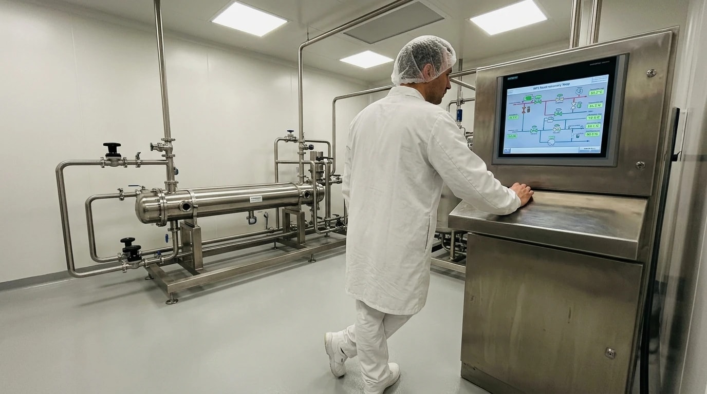
Every component of a WFI heat recovery system must meet stringent sanitary design standards to ensure that no part of the system becomes a breeding ground for bacteria or chemical impurities.
Surface Roughness and Microbial Control
To prevent bioburden accumulation, all product-wetted parts in the heat recovery system must meet strict sanitary design standards, specifically the ASME BPE (Bioprocess Equipment) guidelines. Standing water or microscopic crevices can quickly host bacterial colonies, leading to biofilm formation that contaminates the high-purity loop.
Consequently, internal surfaces are electropolished to a surface roughness of Ra ≤ 0.38 µm (15 µin), conforming to the ASME BPE SF4 designation. This process removes microscopic peaks and leaves a chromium-enriched passive oxide layer that resists biofilm adhesion and eliminates potential microbial nesting sites.
Metallurgical Requirements and Corrosion Resistance
The high operating temperatures of WFI systems, combined with the low conductivity of pure water, accelerate corrosion in standard metals. Clean utility design teams typically specify high-grade, low-carbon stainless steel, specifically AISI 316L (UNS S31603). Low-carbon steel prevents chromium carbide precipitation at the grain boundaries during welding, maintaining high corrosion resistance and preventing localised pitting.
For highly aggressive utility streams or corrosive pure water, design teams may evaluate premium alloys such as Duplex stainless steel or Hastelloy. All tubes are pickled and passivated post-manufacture to form a protective chromium oxide layer that prevents the formation of 'rouge' (iron oxide particles).
Self-Draining and Zero Dead-Leg Engineering
To prevent the heat recovery system from becoming a source of bioburden, the physical installation must be completely self-draining. Engineers typically install DTS heat exchangers vertically or in an inclined position.
The design must feature zero dead-legs, ensuring there are no stagnant pockets where water can pool when the loop is drained. Product-side connections utilise sanitary Tri-Clamp fittings in compliance with ASME BPE guidelines to guarantee crevice-free seals.

Pinch analysis identifies the thermodynamic minimum energy requirement of your process — then designs the heat exchanger network to achieve it.
Managing Thermal Shock and Sanitisation in WFI Loop Systems
Operating a heat recovery system within a WFI storage and distribution loop requires managing intense, repetitive temperature shifts.
The 24-Hour Sanitisation Rule under UK GMP Regulations
Under the UK GMP regulations enforced by the MHRA, any cold WFI sub-loop operating below 70°C (typically around 15°C to 25°C) must be either discarded or thermally sanitised back above 80°C at least once every 24 hours. This preventative measure stops bioburden building up in sections of the loop that operate at lower temperatures. When a sanitisation cycle is initiated, hot WFI at 80°C or pure steam is routed through the sub-loop, creating a massive temperature swing within the heat exchanger.
Thermal Expansion and Stress Relief
This rapid transition from 25°C cooling to 80°C sanitisation creates intense thermal shock. Because the tubes and the shell expand at different rates depending on their temperatures and material thicknesses, mechanical stress accumulates rapidly. If the heat exchanger is completely rigid, these thermal forces can crack the tube-to-tube-sheet welds. To absorb this differential thermal expansion, engineers include expansion bellows in the shell or utilise a flexible floating head design that accommodates expansion without stress accumulation.
Pure Steam and CIP/SIP Cycle Compatibility
The heat recovery unit must also withstand Clean-in-Place (CIP) and Steam-in-Place (SIP) operations. SIP cycles introduce saturated pure steam at temperatures between 121°C and 135°C. The gaskets and seals used in the DTS exchanger must be fully compliant with US FDA 21 CFR 177.2600 and USP Class VI standards, ensuring they do not degrade, leach chemical compounds, or lose elasticity under repeated steam exposure.
Pinch Analysis Methodology for Optimising Pharmaceutical Water Utilities
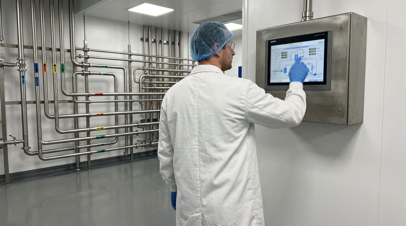
Applying Pinch Analysis to high-purity water networks allows clean utility engineers to map the thermal loads of the entire clean utility system and identify the 'pinch temperature'. This is the thermal boundary above which only heating is required, and below which only cooling is needed. In pharmaceutical manufacturing, this approach pinpoints exactly where waste heat can be recycled to offset external utility loads.
Practical Heat Recovery Configurations
The integration of a DTS heat exchanger for Water for Injection (WFI) heat recovery typically involves routing the hot WFI return line through the tube side of a DTS exchanger, while the incoming cold Purified Water (PW) make-up feed passes through the shell side. This recovers thermal energy to preheat the feedwater before it enters the distillation unit.
Because distillation (via multi-effect or vapour compression systems) requires the feedwater to be heated to boiling, preheating the incoming cold water significantly reduces the boiler steam load. This direct thermal integration reduces the boiler utility demand by up to 25 per cent and lowers the cooling tower load by a corresponding amount.
To model the thermal capacity of this heat recovery process, engineers apply established heat transfer relationships. The thermal duty of the DTS heat exchanger is calculated as follows:
Q=U⋅A⋅ΔTlmwhere:
- Q is the total thermal heat transfer rate (W)
- U is the overall heat transfer coefficient (W/m²°C)
- A is the effective heat transfer area (m²)
- ΔTlm is the logarithmic mean temperature difference (°C)
The logarithmic mean temperature difference (ΔTlm), which represents the effective thermal driving force across the exchanger, is calculated by:
ΔTlm=ln(ΔT1/ΔT2)ΔT1−ΔT2where:
- ΔT1 is the temperature difference between the hot and cold fluid streams at one end of the exchanger (°C)
- ΔT2 is the temperature difference between the hot and cold fluid streams at the opposite end of the exchanger (°C)
In a double tube sheet heat exchanger, the overall heat transfer coefficient U is slightly lower than that of a standard shell and tube exchanger due to the increased resistance of the dual sheets and the physical air gap. The dual tube sheets create a small dead zone near the ends of the tube bundle where no heat transfer occurs. Clean utility thermal engineers must account for this inactive length by increasing the overall heat transfer area A by approximately 5 to 10 per cent to achieve the desired thermal recovery targets without under-sizing the unit.
Consider a typical heat recovery scenario across a UK pharmaceutical facility:
- Cold Purified Water (make-up feed) enters the facility utilities at 15°C at a flow rate of 2,000 kg/h.
- Hot WFI returning from the distribution loop at 80°C must be cooled to 20°C to feed an ambient formulation vessel.
- A DTS heat exchanger is installed to recover heat from the returning hot WFI, preheating the incoming cold Purified Water feed.
- The return hot WFI is cooled from 80°C to 35°C, transferring 376,000 kJ/h (approximately 104 kW) of thermal energy to the feedwater.
- The Purified Water feed is preheated from 15°C to 60°C before entering the WFI distiller.
- This direct thermal integration reduces the boiler steam demand on the distiller by approximately 104 kW, translating to an annual carbon saving of over 45 tonnes of CO₂e (assuming continuous operation for 8,000 hours per year and a standard natural-gas-fired boiler efficiency of 80 per cent).
By reducing both steam and cooling water demand, this configuration provides a swift return on investment while helping the facility achieve its carbon reduction goals.
Validation, Testing, and Lifecycle Maintenance of DTS Exchangers
Commissioning and maintaining double tube sheet exchangers in high-purity systems requires strict adherence to validation protocols. The system must undergo rigorous testing to ensure both cleanability and physical integrity.
Commissioning and Riboflavin Testing
Commissioning a new clean utility heat recovery system requires strict validation protocols to meet UK GMP and MHRA guidelines. ASME BPE Appendix L defines the protocol for verifying that all internal process surfaces are fully wetted and cleanable. In a DTS heat exchanger, the tube-side wetted areas must be tested.
The tubes are coated with a fluorescent riboflavin (vitamin B2) solution, which fluoresces brightly under ultraviolet (UV) light. A standardised CIP water rinse is then run through the system. Following the rinse, engineers inspect the tube interior using a high-definition borescope equipped with a UV light source to confirm that all traces of the riboflavin have been removed. This validates that the heat exchanger has zero dead zones or 'shadow areas' that could harbour microbial bioburden.
Non-Destructive Testing and Joint Integrity
The integrity of the tube-to-tube-sheet welds is critical. During fabrication and annual maintenance shutdowns, engineers conduct advanced non-destructive testing (NDT), such as helium leak testing, eddy current testing, and dye penetrant inspection. Because the inner tube sheet is physically nested behind the outer tube sheet, inspecting the inner welds requires specialised long-bore borescopes and advanced NDT probes.
Rouge Monitoring and Remediation
Rouge is a common phenomenon in high-temperature stainless steel WFI systems, consisting of iron oxide deposits that form as the passive layer degrades. In a DTS heat exchanger, rouging on the WFI side reduces heat transfer efficiency and risks shedding particles into the sterile loop.
Utility teams continuously monitor rouge build-up using sanitary sight glasses and schedule chemical derouging cycles using phosphoric or oxalic acid, followed by passivation to restore the AISI 316L passive layer. This maintenance keeps heat transfer efficient and prevents potential bioburden nesting sites from forming inside the tubes.
This article reflects the independent analysis and editorial opinion of EnerTherm Engineering. Product names, trademarks, and brands mentioned belong to their respective owners. EnerTherm Engineering is not affiliated with, endorsed by, or a licensee of any third-party software or product mentioned unless explicitly stated.

Managing Director — EnerTherm Engineering
Dr. François Pierrel is Managing Director of EnerTherm Engineering with over two decades of expertise in thermal design, heat transfer, and industrial energy optimisation. He holds a PhD in Heat Transfer from Cranfield University and a Post-Doctorate from Heriot-Watt University.
