Why Load Profiling Must Precede Industrial VSD Sizing
BS EN IEC 61800-9-2:2025+A1:2026 links VSD sizing to speed and torque profiles.
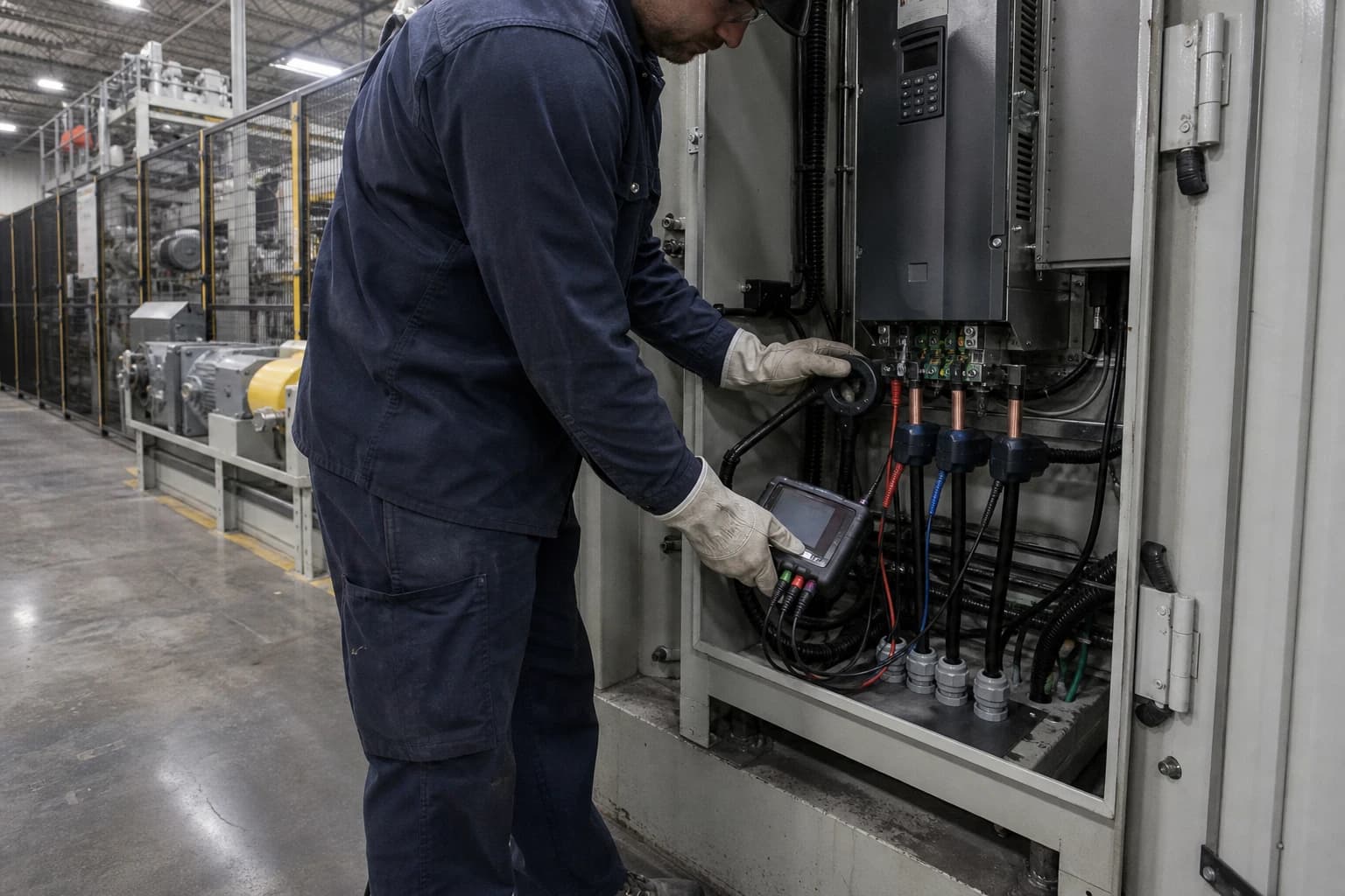
Industrial motor drive optimisation matches a motor and variable speed drive to the measured speed, torque and operating time required by the driven machine. Load profiling must therefore precede VSD sizing: a motor nameplate describes rated capability, while a load profile shows what the process requires.
A 45 kW motor on a plastics line may draw modest power for most of a shift, then face a short high-torque event at start-up or during a material change. A fan may run against a partly closed damper for thousands of hours, yet need full flow during extraction peaks. A conveyor can spend more energy waiting than moving. Each case requires a different VSD specification and may warrant a different energy-saving measure.
BS EN IEC 61800-9-2:2025+A1:2026 covers ecodesign for motor systems, including energy-efficiency determination and classification. Its subject is the motor system, not an isolated nameplate figure. The standard reinforces a practical engineering rule: selection must reflect the driven load’s speed-torque behaviour and the time spent at relevant operating points.
For manufacturers pursuing industrial motor drive optimisation, load profiling converts a generic retrofit proposal into a defensible design, energy and peak-demand decision.
Why motor nameplate data cannot size a VSD
Rated power is available capacity
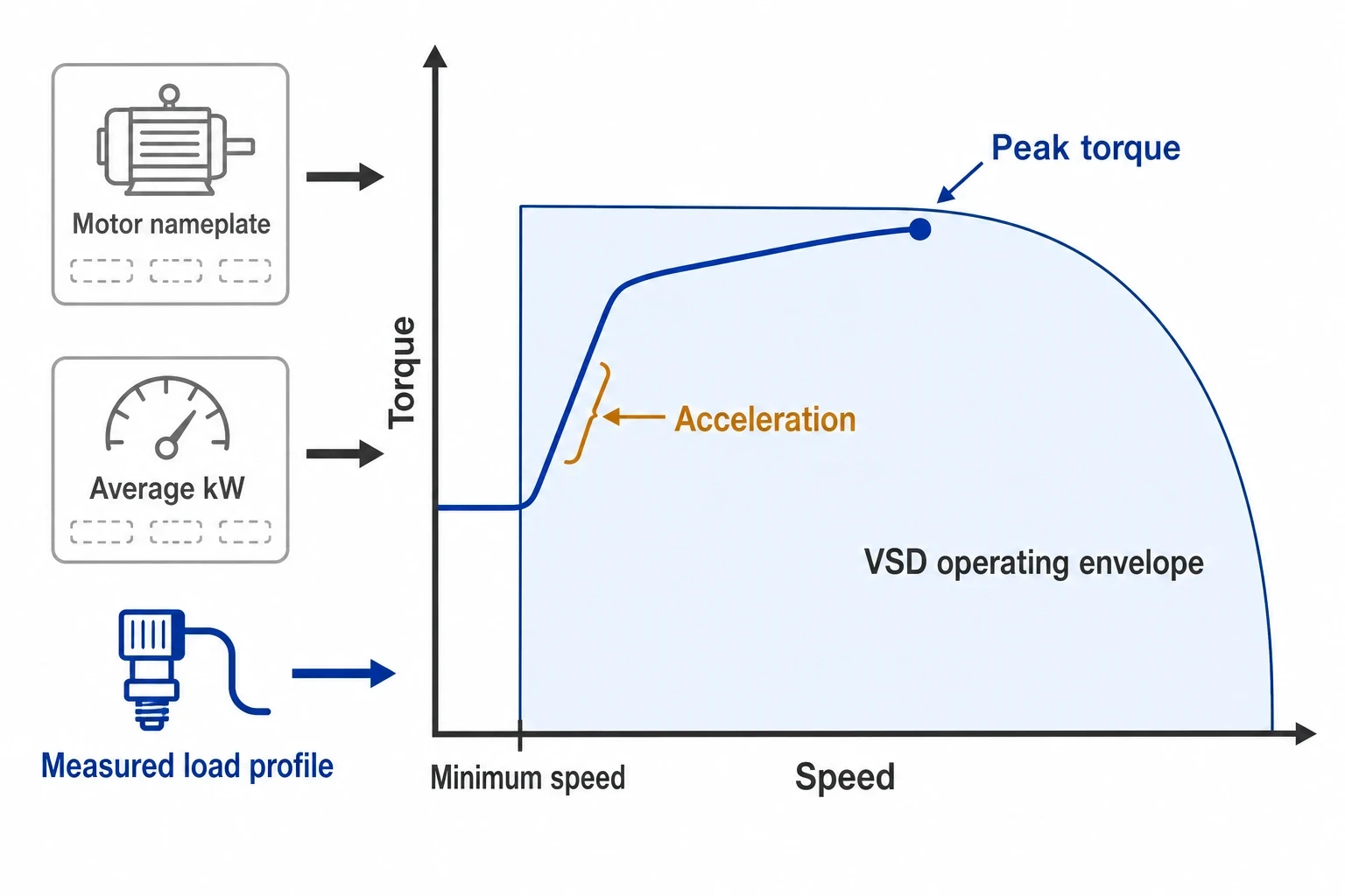
A motor nameplate states rated output, voltage, current, speed, duty and other design information. It does not establish how much shaft power the machine consumes during normal production.
Historic designs often contain margin. Production may have changed, equipment may have been replaced conservatively after a failure, or a line may run fewer hours than its original design basis. A motor can therefore be materially oversized for its usual duty while still needing high torque for a short operating event.
Sizing a VSD solely from motor kW can lead to unnecessary capital cost, larger enclosure requirements and avoidable electrical losses. Sizing from average measured kW creates the opposite problem. The drive may trip during acceleration, fail to deliver required torque or constrain production at its highest-demand state.
A VSD follows the load characteristic
The Energy Technology List describes a VSD as an electronic power converter that controls motor speed, torque and mechanical power output. Its criteria require the output to suit the load’s torque-speed characteristic, including quadratic and linear characteristics.
The driven equipment matters as much as the motor:
- Centrifugal fans and pumps generally have quadratic torque behaviour.
- Conveyors, mixers, extruders and positive-displacement pumps often need broadly constant torque.
- Crushers, mills, winding equipment and intermittent assembly machinery may have irregular load peaks.
- Equipment with frequent idle periods may benefit more from automatic switch-off or sequencing than speed reduction.
A VSD must meet the required operating envelope, including the highest sustained load, acceleration events, minimum stable speed and control response. A nameplate does not provide that evidence.

Identify where your plant is losing energy and quantify the savings potential — our audits map every heat source, sink, and waste stream in your facility.
What an industrial motor load profile should measure
Establish the electrical boundary
A power analyser at the motor feeder can record voltage, current, real power, apparent power, power factor, demand and energy consumption. For an existing VSD installation, measurement should distinguish the electrical input to the drive from the motor-side output.
This boundary affects both the energy baseline and equipment comparison. The Energy Technology List uses combined motor-and-VSD efficiency for converter-fed motor-drive units and matched packages. Its test route based on BS EN IEC 60034-2-1:2024 requires input-power measurement at the VSD’s main input terminals. This captures drive and motor losses together.
Motor efficiency remains relevant, but it does not account for drive losses or energy lost through a damper, throttling valve, bypass line or excessive pressure setpoint.
Connect electrical demand to process demand
Electrical measurements need a process counterpart. The useful variables depend on the equipment:
| Driven equipment | Process evidence | VSD sizing significance |
|---|---|---|
| Extraction fan | Airflow, static pressure, damper position, filter condition | Identifies usable speed reduction and full-flow requirement |
| Centrifugal pump | Flow, differential pressure, valve position, tank level | Reveals throttling loss, static-head limits and minimum-flow constraints |
| Conveyor | Product rate, starts, stops, loading condition | Defines acceleration and loaded-start requirements |
| Mixer or extruder | Batch condition, product recipe, throughput, torque demand | Identifies constant-torque duty and overload events |
| Compressor auxiliary | Pressure control, running state, inlet control position | Tests whether speed control will reduce unloaded operation |
Current is not a direct torque measurement. It is useful evidence, particularly when combined with speed and real-power data, but motor magnetising current and changing motor efficiency can distort a simple current-to-torque assumption. Direct torque measurement can add value where safe shaft access exists. In many plants, engineers can derive a sound profile from electrical measurement, tachometry, control signals and production records.
Capture the states that determine capacity
A useful profile separates operating states rather than producing one site-wide average. It should capture:
- Start-up current, acceleration duration and whether the machine starts loaded.
- Normal production kW, speed, output rate and control positions.
- The highest sustained current and its duration.
- Short overload events caused by product changes, jams, cold starts or pressure excursions.
- Low-demand operation, including the process speed needed to maintain quality.
- Idle, standby and out-of-production running.
- Cleaning, changeover and maintenance modes where the equipment must remain available.
A short spot reading can identify obvious underload. It cannot establish annual consumption or prove that a smaller VSD will survive the duty cycle.
How load type changes the VSD opportunity
Fans and pumps require system-curve evidence
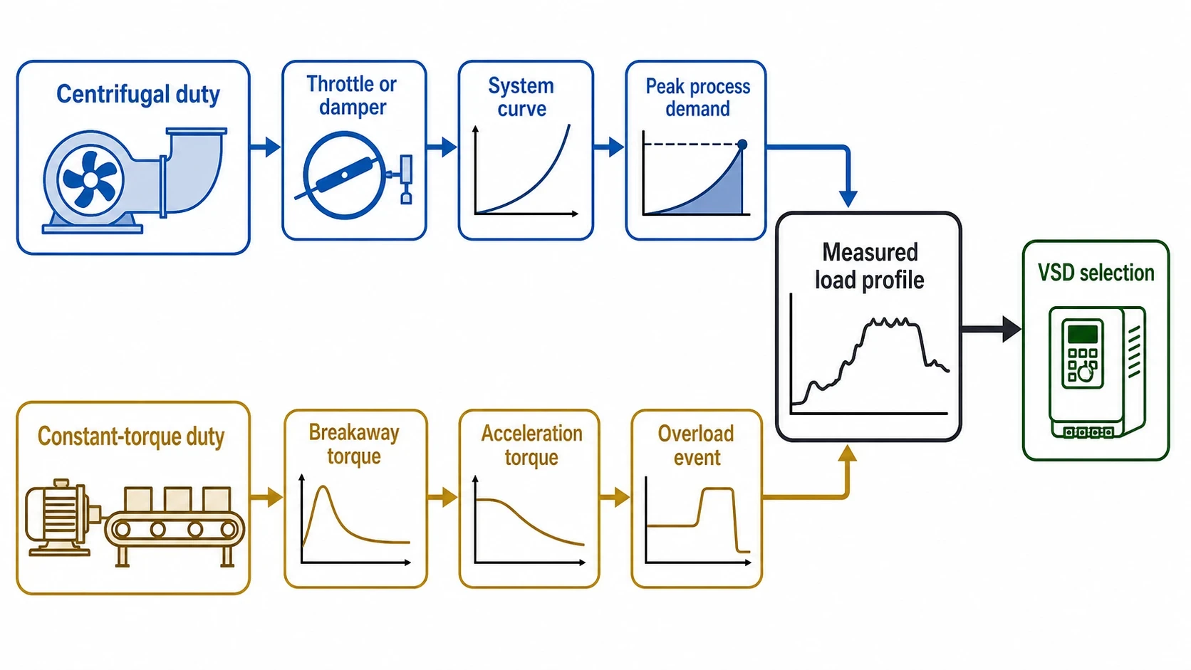
Centrifugal fans and pumps often offer a strong VSD case where operators control flow with dampers, throttling valves or bypasses. Lower speed can substantially reduce the energy needed by rotating equipment when the system allows it.
The opportunity depends on the full system curve. Static head, duct resistance, pipe resistance, filtration condition, pressure setpoint and required turndown all influence the result. A fan with a nearly closed damper may appear ideal for speed control, yet require close to full speed when extraction demand rises or filters load. A transfer pump may run at low average flow but still need full head during a defined production step.
The profile must include the conditions that create the highest process requirement. It should also record mechanical control positions, since a VSD cannot deliver its expected benefit if dampers or valves remain partly closed after commissioning.
Constant-torque machinery needs overload detail
Many manufacturing assets need broadly constant torque across their working speed range. Examples include conveyors, screw feeders, mixers, positive-displacement pumps, mills and extrusion equipment.
A VSD can improve control, reduce mechanical shock at start-up and match output to production demand. The energy case differs from that for a centrifugal fan or pump: reduced speed does not produce the same relationship between speed and absorbed power.
For these duties, profiling should establish:
- Breakaway torque.
- Loaded acceleration torque.
- Continuous running torque.
- Overload magnitude and duration.
- Required torque at low speed.
- The effect of material condition, temperature and product grade.
A drive selected around average kW may run successfully during light production, then trip during a loaded restart. The VSD’s published overload capability, duration and repetition rate must be checked against measured events.
Intermittent duty may call for another measure
Assembly lines, presses, winding systems and batch equipment can have pronounced starts, stops and idle periods. Their energy use may depend more on operating discipline and sequencing than continuous speed control.
The current ESOS Phase 4 guidance identifies high-efficiency motors, VSDs, automatic switch-off controls, time switches, interlocks, sensors and motor-output monitoring as measures to consider for motors and drives. Load profiling provides the evidence to distinguish between them.
A profile showing long idle periods may support automatic switch-off controls. A profile showing fixed-speed operation at near-rated load may point to motor replacement or mechanical maintenance. A profile showing a throttled variable-flow duty may support a VSD retrofit.

Identify where your plant is losing energy and quantify the savings potential — our audits map every heat source, sink, and waste stream in your facility.
Sizing a VSD from measured duty
Begin with current, torque and operating time
VSD selection begins with the highest required process operating point. The engineer then checks the motor and drive against the measured duty.
The main checks include:
- Continuous motor current at normal and highest sustained production demand.
- Required speed range, including the minimum speed that keeps the process stable.
- Acceleration and deceleration requirements.
- Starting condition, including loaded starts and restart frequency.
- Short-duration overload current, torque and repetition rate.
- Required low-speed torque.
- Any regenerative braking or controlled stopping requirement.
Drive kW provides a useful initial filter. Drive output-current rating and overload capability determine whether the selected drive can perform the duty.
Use a load-duration view
A load-duration chart or histogram shows how long the motor spends at different power and speed levels. It shows where annual energy is consumed and where short peaks occur.
For example, a motor may spend most operating hours at 45% output, run briefly at 80% output during changeovers and require high current for a loaded start. Long periods at reduced demand shape annual savings; short periods set VSD overload and ramp requirements.
Average demand belongs in the financial model, but it cannot set a drive rating without peak-duty information.
Check the motor as part of the retrofit
The existing motor needs assessment before connection to a VSD. Relevant issues include:
- Insulation suitability for converter supply.
- Cable length and reflected-wave risk.
- Bearing-current control.
- Motor cooling at low speed.
- Lubrication and bearing limits.
- Equipment resonance across the intended speed range.
- Pump minimum-flow requirements.
- Fan surge or unstable operating regions.
- Hazardous-area obligations where applicable.
The Ecodesign for Energy-Related Products and Energy Information Regulations 2021 form part of the UK product framework for applicable energy-related products. Product compliance and site suitability are separate questions. A compliant product still requires a duty-specific design and commissioning plan.
Whole-system efficiency is the procurement metric
Compare the package at the measured duty
The Energy Technology List covers converter-fed motor products with rated motor outputs from 0.12 kW to 1,000 kW. It includes converter-fed AC motors, integrated motor-drive units and matched motor-drive packages.
For integrated units and matched packages, the relevant full-load performance figure is the combined efficiency of the VSD and motor. This is a better procurement starting point than a motor efficiency figure alone.
The final selection should go further. Thermal design teams typically compare candidate equipment against the site’s measured speed and torque points. A full-load value may not represent the condition in which a manufacturing line spends most of its operating hours.
Account for process losses
Industrial motor drive optimisation concerns useful process work, not electrical conversion alone. A highly efficient motor and VSD combination can still consume unnecessary electricity if the driven equipment operates against an unnecessary pressure setpoint or through a permanent bypass.
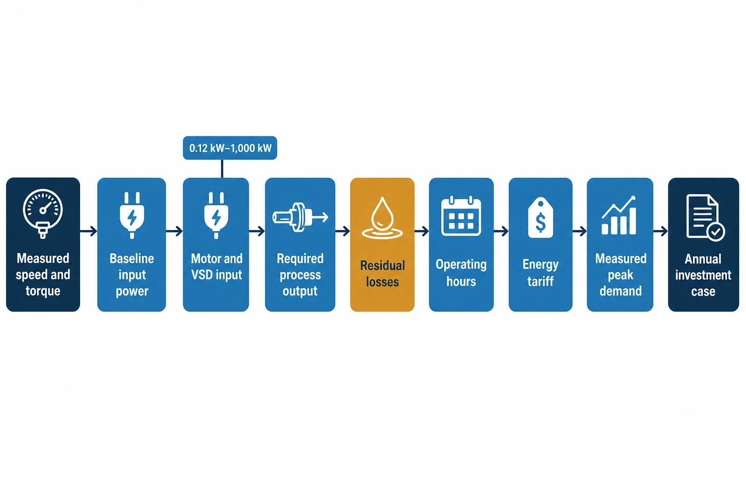
The annual model should include:
- Baseline input power at each measured state.
- Expected VSD and motor input power at the proposed speed.
- Process output required at that state.
- Remaining damper, valve or bypass losses.
- Operating hours for each state.
- Tariff periods and measured peak demand where relevant.
This produces an investment case based on expected operation, not an advertised percentage saving.
Commissioning and verification protect the savings case
Commission to the profiled operating envelope
Commissioning should confirm operation across the duty used for selection. Rotation direction and fault-free running are necessary checks, but they do not prove that the retrofit delivers the intended result.
The commissioning record should include process output, speed limits, control setpoints, acceleration and deceleration ramps, input power, current and operating hours. It should confirm that operators can meet production requirements at the new control settings without reintroducing mechanical throttling.
The record should also state the safeguards required by the driven equipment. A pump may need a minimum-speed limit. A fan may need defined exclusion speeds to avoid vibration. A conveyor may require a controlled ramp to prevent product displacement.
Verify against the agreed baseline
A measurement and verification plan should be defined before installation. IPMVP-aligned practice provides a structured basis for comparing post-installation consumption with the agreed baseline while allowing for material changes in production, operating hours or process conditions.
For a VSD retrofit, the plan should set out:
- The measurement boundary.
- Baseline monitoring period and operating states.
- Meters, analysers and process signals to be used.
- Production or throughput variables used for normalisation.
- Post-installation review period.
- Responsibility for data collection and setpoint control.
The result supports credible payback, net present value and internal rate of return calculations. It also identifies whether the equipment is operating to its intended control strategy months after commissioning.
This article reflects the independent analysis and editorial opinion of EnerTherm Engineering. Product names, trademarks, and brands mentioned belong to their respective owners. EnerTherm Engineering is not affiliated with, endorsed by, or a licensee of any third-party software or product mentioned unless explicitly stated.

Managing Director — EnerTherm Engineering
Dr. François Pierrel is Managing Director of EnerTherm Engineering with over two decades of expertise in thermal design, heat transfer, and industrial energy optimisation. He holds a PhD in Heat Transfer from Cranfield University and a Post-Doctorate from Heriot-Watt University.
