Why Variable Frequency Drive Load Profiles Beat Nameplates
How torque and speed profiles reveal VSD retrofit opportunities in UK plants.
A variable frequency drive, also called a variable speed drive or VSD, is an electronic controller that changes an AC motor’s speed by varying the frequency and voltage supplied to it.
A motor nameplate states its rated kW, voltage, current, speed and efficiency at specified conditions. It does not show how the motor behaves through a production week. That distinction determines whether a VSD retrofit will save significant electricity, create process problems, or add losses and complexity.
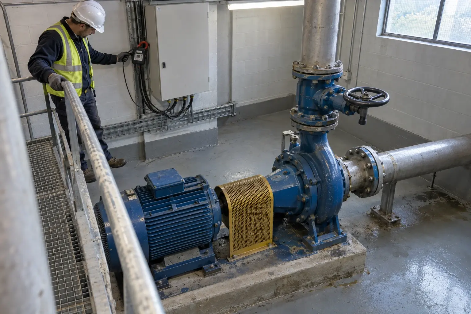
A 30 kW motor on a cooling-water pump may run close to nameplate duty for only a few hours each week. For the rest of the time, it may push excess flow against a throttling valve. Reducing speed can then cut pump power sharply. Another 30 kW motor may drive an extruder that needs near-constant torque and stable screw speed throughout each shift. A VSD may improve control or starting behaviour, but the electricity case can be weak.
That is why variable frequency drive (VSD) optimisation starts with a load profile, not a motor schedule. The profile records what the driven equipment demands, at what speed, torque and process condition, and for how long.
What a VSD nameplate can and cannot tell an energy audit
Nameplate values are design limits
The motor nameplate remains essential. It establishes the electrical and mechanical limits for a survey: rated output power, voltage, full-load current, frequency, rated speed, insulation class and efficiency class. Engineers use it to assess cable ratings, overload capability, starter replacement, protection settings and compatible drive size.
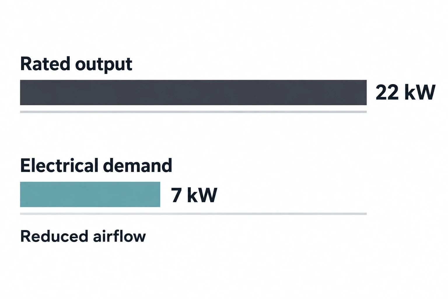
Rated kW is mechanical shaft output at rated conditions. It is not a reading of the motor’s present electrical demand. A fan motor marked 22 kW may draw 7 kW at a reduced airflow condition. Conversely, a conveyor motor may draw high current during loaded starts while consuming far less power once product flow settles.
A nameplate also cannot identify:
- Hours at full, part and idle load.
- Whether flow is controlled by a damper, throttle valve, bypass or intermittent start-stop operation.
- The relationship between motor speed and the production requirement.
- Motor efficiency at the actual load point.
- Drive losses at the frequencies and torque levels used in practice.
- The effect of process changes, shift patterns, cleaning cycles and seasonal ambient conditions.
A spreadsheet that ranks opportunities only by motor nameplate kW can overstate some projects and miss others. A smaller fan running 8,000 hours a year with a wide turndown requirement can offer a stronger case than a larger motor operating near its design point for a limited campaign.
Compliance testing is not a site duty cycle
The Ecodesign for Energy-Related Products and Energy Information (Amendment) Regulations 2021 specify a common point for determining the IE class of a VSD: 100% rated torque-producing current and 90% rated motor stator frequency. This produces a comparable loss figure for product classification.
That test point is useful for procurement. It does not represent the operating profile of a particular pump, fan, compressor or mixer. A site may run a 50 Hz-rated motor at 35 Hz for most of the year, at modest torque, then require brief high-load periods during production changeover. The loss behaviour of the motor-drive system, and savings against its fixed-speed control method, must be assessed across that pattern.
Commission Regulation (EU) 2019/1781 specifies an IE2 maximum-loss requirement for VSDs intended for motors from 0.12 kW to 1,000 kW. From 1 July 2021, the IE2 maximum is 25% lower than the regulation’s reference VSD-loss value. This is a product requirement, not evidence that every installed VSD will deliver worthwhile site savings.

Identify where your plant is losing energy and quantify the savings potential — our audits map every heat source, sink, and waste stream in your facility.
Why load profiles improve VSD retrofit decisions
Energy follows operating points over time
A load profile turns a single rating into a record of operating points. At a minimum, it should show kW, current, voltage, power factor, drive output frequency or speed, and operating hours. The process variable matters as much as the electrical data: pressure, flow, temperature, air volume, line speed, product throughput or tank level should be recorded alongside it.
The result identifies where energy and process demand diverge. A cooling fan held at full speed while a damper restricts air volume presents a different opportunity from a fan whose airflow must remain high throughout every shift. Likewise, a pump with a heavily throttled discharge valve can be a VSD candidate, but only after review of the pump curve, system curve and required minimum flow.
For a variable-torque centrifugal load, flow changes broadly with rotational speed, while absorbed power can fall much faster as speed reduces. The familiar affinity-law relationship is useful only within its correct application. It works best where friction head dominates. Static lift, fixed pressure requirements, recirculation and a poorly matched pump can materially reduce the benefit.
Torque profile separates suitable and unsuitable applications
Drive frequency alone is an incomplete proxy for load. A VSD operating at 35 Hz with a lightly loaded fan differs from one operating at 35 Hz on a high-torque mixer. The audit should establish the mechanical load type.
| Driven equipment | Typical load characteristic | VSD optimisation question |
|---|---|---|
| Centrifugal pumps and fans | Variable torque | Does the process frequently require less flow or pressure than full-speed operation provides? |
| Blowers | Often variable torque, but process-dependent | Can speed meet air demand without compromising pressure, combustion or pneumatic conveying? |
| Conveyors | Usually constant torque | Will speed control reduce idle running or improve line matching enough to justify the drive? |
| Extruders | Constant torque with process limits | Does the production recipe permit lower screw speed, and what happens to product quality? |
| Mixers and agitators | Application-dependent | Can reduced speed retain mixing, suspension, heat transfer and batch consistency? |
| Compressors | Compressor and control-specific | Does a VSD complement the existing base-load and trim-control arrangement? |
A motor that is lightly loaded at full speed does not automatically require a VSD. It may be oversized, mechanically inefficient or operating with an unnecessary process setpoint. Correcting the setpoint, impeller diameter, damper position, pipe restriction, control logic or motor size may offer a better first intervention.
Production context prevents false savings claims
A useful profile captures normal operation and the exceptions that determine plant reliability. Metals plants may have hot-weather ventilation peaks, furnace interlocks and extraction demand during particular operations. Plastics sites may have cooling loads linked to moulding cycles and ambient wet-bulb conditions. Assembly operations may have intermittent conveyors and extraction running long after production stops.
A short spot measurement can misclassify these loads. Monitoring should cover representative shifts, product variants and operating states. The audit record should also note:
- Start and stop frequency.
- Valve, damper and bypass positions.
- Control setpoints and manual overrides.
- Planned downtime and unplanned stoppages.
- Parallel equipment operating status.
- Process quality constraints and minimum safe speeds.
This evidence allows an investment case to distinguish controllable demand from unavoidable demand.
How to measure a VSD load profile on site
Establish the system boundary before fitting instruments
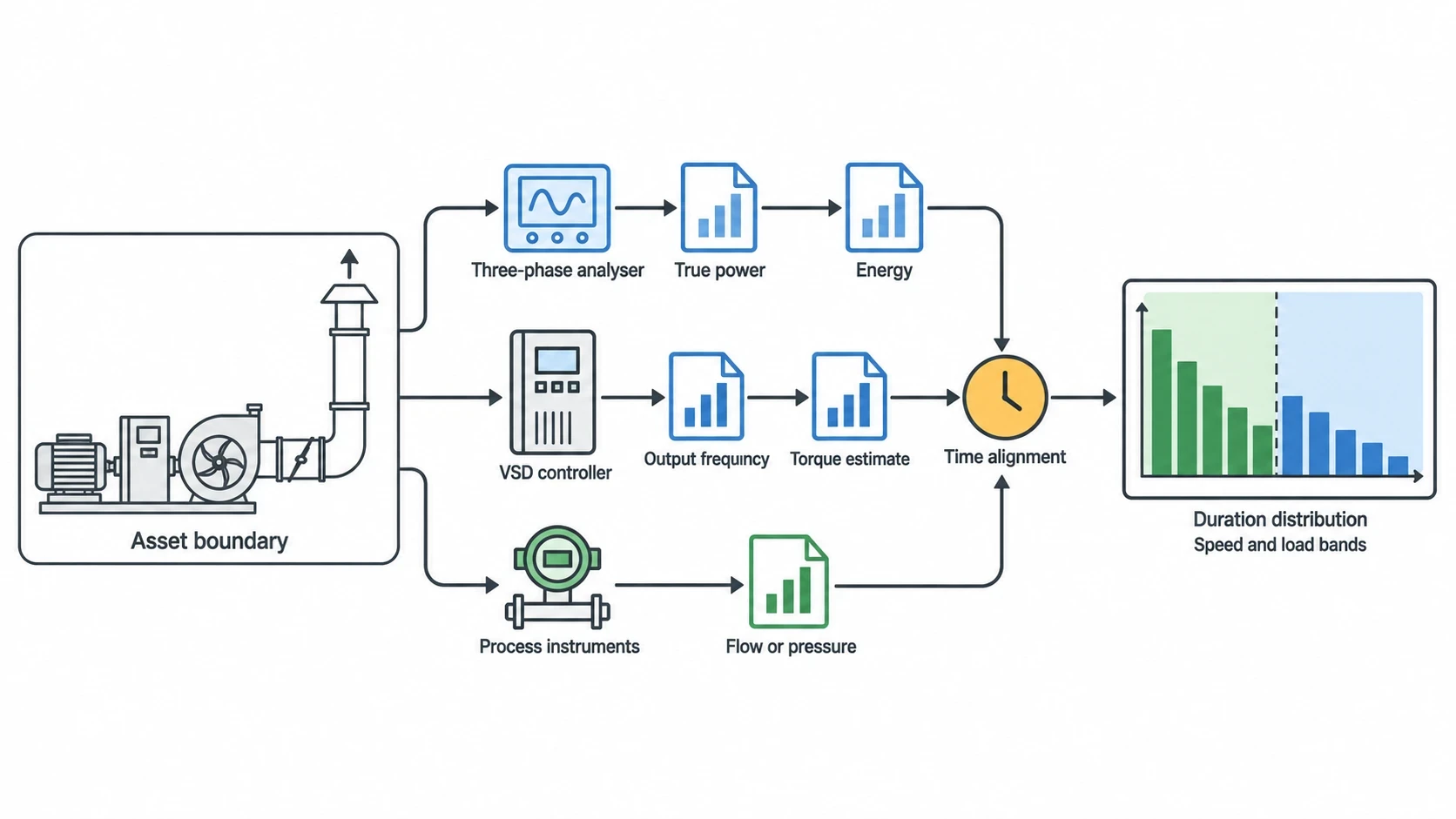
The first task is to define the asset boundary. For a fan, this may include the motor, existing starter or drive, fan, damper, ductwork and controlled extraction point. For a pump, include the motor, pump, valves, bypasses, pipework and delivered flow or pressure point.
Record the motor and driven-equipment details, then confirm the control arrangement in the field. Drawings are often incomplete, and operator practice can differ from the stated philosophy. A bypass valve left open, a damper locked in position or a pressure setpoint raised after a production issue can alter the VSD case completely.
Measure electrical and process data together
Non-intrusive monitoring is normally the practical starting point. A three-phase power analyser can log true power, current, voltage, power factor and energy. Where a VSD is already installed, its controller may provide output frequency, speed reference, torque estimate and status signals. Independent electrical measurement remains valuable for checking the whole supply-side picture.
Pair those records with process instruments. Clamp-on ultrasonic flow measurement can support water-system assessments without cutting pipework. Differential pressure, temperature, air velocity, static pressure and production counters may be needed depending on the duty. Thermal imaging can identify hot connections, overloaded panels or ventilation conditions, although it does not replace electrical measurement.
Sampling intervals should match the process. A slow cooling-water profile may suit one-minute or five-minute records. Intermittent machinery, rapid pressure cycling and batch transitions may require faster logging to avoid averaging away the behaviour that controls energy use.
Check data quality before calculating savings
Engineers should reconcile logged kWh against the sub-meter or a temporary revenue-grade meter where possible. They should check that timestamp clocks align between electrical and process data, identify gaps, and flag periods when sensors disconnected or production was abnormal.
The final profile should include a duration distribution: the percentage of operating time at each speed and load band. This shows whether the equipment spends enough time away from full speed for variable-speed control to change annual consumption.
Selecting VSD opportunities in manufacturing
Strong candidates: excess flow controlled by restriction
Pumps and fans are often strong candidates where a fixed-speed motor produces more flow than the process needs and a restrictive device removes the surplus. Common examples include:
- Cooling-water pumps throttled to control temperature.
- Dust-extraction fans controlled by dampers as machines start and stop.
- Process-air fans held at full speed against varying kiln, oven or dryer demand.
- Secondary pumping circuits serving variable production loads.
- Ventilation systems operating at full volume outside occupied or production periods.
The process constraint comes first. A VSD control strategy must maintain minimum airflow for safety, prevent inadequate cooling and keep pumps above any required minimum flow. For combustion air, speed reduction must be considered alongside burner controls and applicable safety arrangements.
Weak candidates: high load and stable duty
Some applications have little usable speed range. A constant-torque conveyor operating continuously at its required line speed may consume less with a high-efficiency motor or improved mechanical maintenance, but a VSD will not create a large energy reduction if output speed cannot fall.
The same caution applies to extrusion, crushing, positive-displacement pumping and mixing duties where torque remains substantial as speed changes. A VSD can provide soft starting, controlled acceleration, improved process control or reduced mechanical stress. These are legitimate benefits, but they should be separated from the electricity-saving case.
Assess the whole motor-drive system
BS EN IEC 61800-9-2:2025 addresses the energy-efficiency determination and classification of adjustable-speed electrical power drive systems. For a site project, the motor, complete drive module and driven equipment should be evaluated as a system across the actual speed-torque profile.
Drive losses matter, especially where the motor has limited time at reduced speed. A retrofit assessment should account for VSD losses, motor behaviour at reduced speed, cooling at low motor speed, and energy used by auxiliary cooling equipment.
The UK Energy Technology List remains useful as a procurement screen. It includes motor-drive technologies and provides independently assessed product information. During its stated transition arrangements, it continues to accept results tested to BS EN 61800-9-2:2017 for relevant criteria. Product eligibility should still be followed by application-specific duty analysis.

Identify where your plant is losing energy and quantify the savings potential — our audits map every heat source, sink, and waste stream in your facility.
Engineering checks before a VSD retrofit
Protect the process and equipment
A viable VSD installation needs more than a savings calculation. Plant teams should review motor insulation suitability, cable length, bearing-current risk, driven-equipment speed limits, low-speed cooling and hazardous-area requirements where applicable. Existing protection and control interlocks need reassessment rather than simple transfer from a direct-on-line starter.
The electrical installation also needs a site-specific review of supply quality, harmonics, electromagnetic compatibility and selected input or output mitigation. The requirement depends on the network and drive arrangement. A generic instruction to fit a filter does not establish compliance or protect a particular installation.
For pumps, check the approved speed envelope, minimum-flow requirement, suction conditions and potential cavitation. For fans, check the stable operating range, required make-up air and effect on extraction capture. For compressors, review the existing control sequence before adding a VSD: inefficient base-load and trim sequencing can consume the apparent savings.
Commission against a documented control strategy
Commissioning should test every operating mode, including start-up, normal production, reduced demand, manual operation, alarm response and plant restart. The control strategy should specify the process setpoint, minimum and maximum speed, sensor-failure response, permissives and handover between parallel machines.
A VSD that meets a kWh model but causes unstable pressure, poor extraction or product-quality variation will not remain in service at its intended setpoint. Operators and maintenance engineers should take part in setting operating limits because they understand conditions that automated logs cannot capture.
Turning load-profile evidence into a credible business case
Prioritise by annual opportunity and operational confidence
An audit should rank each opportunity by annual kWh reduction, expected electricity-cost reduction, carbon impact, installed cost, disruption, process risk and confidence in the evidence. The load profile directly improves that confidence rating.
A transparent case explains the baseline, proposed control change, expected operating hours, measurement period and any avoided maintenance or production benefits. It should distinguish a measured result from an engineering estimate. That gives decision-makers a defensible basis for payback, net present value and internal rate of return calculations.
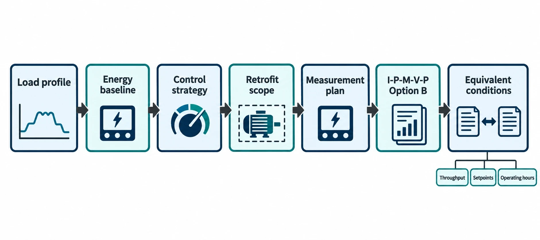
EnerTherm Engineering’s seven-step audit methodology can support this work from initial consultation through on-site measurement, data analysis and prioritised energy-conservation measures. For motor systems, the deliverables should include the load profile, energy baseline, defined control strategy, retrofit scope and measurement plan.
Verify performance after installation
Measurement and verification should be agreed before procurement. The International Performance Measurement and Verification Protocol, IPMVP Core Concepts 2022, provides recognised options for defining the measurement boundary and handling variables.
For a discrete motor retrofit, IPMVP Option B, retrofit isolation with all-parameter measurement, is often appropriate where a power analyser can measure the affected motor system and relevant process variable. A wider system change may need a facility or subsystem boundary, with adjustment for production, weather or operating hours.
The post-installation comparison must use equivalent operating conditions. Comparing a quiet August week after the retrofit with a full-production January baseline creates an attractive chart but not a valid savings result. Recorded throughput, setpoints, ambient conditions and operating hours provide adjustment evidence.
VSD optimisation begins with the duty, not the rating plate
A nameplate establishes what a motor can deliver. A load profile establishes what the plant asks it to deliver. This evidence identifies excess flow, avoids unsuitable fixed-speed control, sizes a VSD properly and quantifies savings without assuming that a large motor creates a large opportunity.
For UK manufacturers working under ESOS or ISO 50001:2018, this approach also produces better audit evidence. ESOS requires energy audits to use verifiable energy-consumption data where reasonably practicable and identify cost-effective measures. A measured motor-system profile gives maintenance, engineering and energy teams a shared basis for acting on that requirement.
The best VSD projects reduce speed only where the process permits it, preserve operating margins and verify the result after commissioning. Load profiling makes those conditions visible.
This article reflects the independent analysis and editorial opinion of EnerTherm Engineering. Product names, trademarks, and brands mentioned belong to their respective owners. EnerTherm Engineering is not affiliated with, endorsed by, or a licensee of any third-party software or product mentioned unless explicitly stated.

Managing Director — EnerTherm Engineering
Dr. François Pierrel is Managing Director of EnerTherm Engineering with over two decades of expertise in thermal design, heat transfer, and industrial energy optimisation. He holds a PhD in Heat Transfer from Cranfield University and a Post-Doctorate from Heriot-Watt University.
