Why UK Food Plants Are Recovering Flash Steam
A technical explainer on flash-steam recovery, boiler efficiency and safe UK operation.
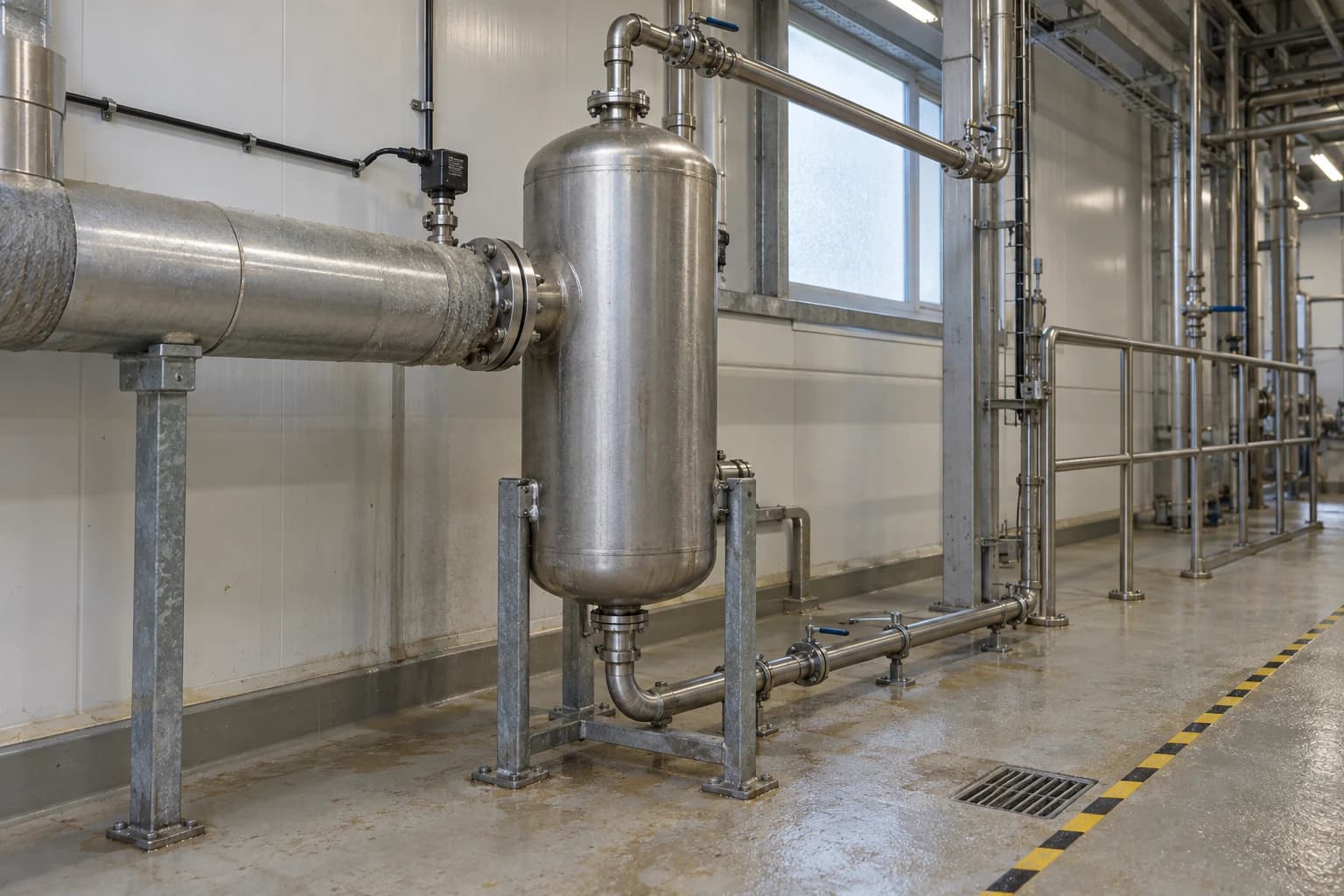
Flash steam is low-pressure steam formed when hot condensate drops from a higher pressure to a lower one and part of the liquid re-evaporates.
For many UK food factories, that vapour has long escaped from condensate receivers, vents and drain lines. It is visible, familiar and easily dismissed as an unavoidable part of steam distribution. It is also usable heat that the boiler plant has already paid to produce.
That matters in a sector with varied thermal loads. Cooking, blanching, brewing, evaporation, pasteurisation, sterilisation, washdown and hot-water production often require steam at different pressures and temperatures across the same site. A plant may generate high-pressure steam for a major process duty, then use pressure-reducing valves to supply lower-pressure users elsewhere. Hot condensate from the high-pressure side can release flash steam as it passes through traps and into lower-pressure pipework.
The UK Energy Technology List sets a useful benchmark for efficient generation. Eligible gas-fired or dual-fuel steam boilers must achieve a net thermal efficiency of at least 92.0% at both 30% and 100% of maximum continuous rating, with a 4:1 turndown requirement. Recovering flash steam does not replace efficient boiler operation. It reduces the live steam needed for suitable lower-temperature duties.
What Flash Steam Recovery Means in Food Manufacturing
Pressure reduction releases useful vapour
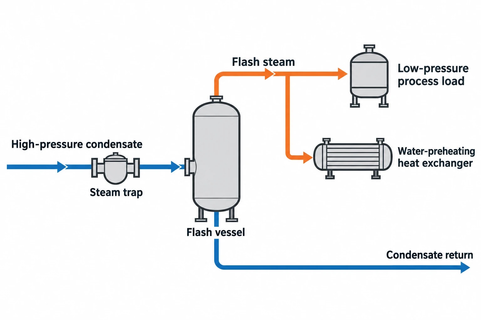
Condensate leaving a heat exchanger or process vessel may be close to the saturation temperature of the steam that supplied it. Once the condensate passes through a steam trap, its pressure falls. At the lower pressure, the liquid contains more heat than saturated water can retain. A proportion therefore boils into flash steam.
The flash fraction depends on:
- The pressure and temperature of condensate upstream of the trap.
- The pressure after the trap, including backpressure in the condensate return system.
- Any subcooling before discharge.
A high-pressure condensate stream discharging to an atmospheric receiver can create substantial flash vapour. A pressurised return arrangement may reduce the pressure step and alter the amount formed. Sites need measured pressures, temperatures and flows before estimating a project case.
Flash steam has the same practical heating value as other saturated steam at the same pressure. A factory can use it to displace live steam at a lower-pressure process load, or condense it through a heat exchanger to preheat water. Venting it wastes heat, treated boiler water and, in many cases, the opportunity to return valuable condensate.
Why food plants have matching heat loads
Food production often combines high-temperature steam users with lower-temperature heating demands. The availability of a suitable low-pressure heat sink is decisive in steam system optimisation for the food industry.
Potential sinks include:
- Process hot-water generation through a heat exchanger.
- Boiler feedwater preheating.
- Low-pressure jacketed vessels.
- Low-pressure calorifiers.
- Air heating where seasonal demand is dependable.
- Water preheating for cleaning operations, where hygienic design and water-quality requirements have been assessed.
The Defra-supported report Utilisation of Waste Heat from Food Factories identifies steam or steam condensate from cooking operations, combustion flue gas and baking-oven exhaust as recoverable food-factory heat sources. The report is older, but its process observation remains relevant: food plants often reject heat while separate utilities continue to consume fuel.

Pinch analysis identifies the thermodynamic minimum energy requirement of your process — then designs the heat exchanger network to achieve it.
Why Condensate Vents Are Now Under Closer Scrutiny
Fuel reduction begins at the utility boundary
A pressure-reducing valve delivers lower-pressure steam by throttling high-pressure steam. It does not recover the sensible heat held in hot condensate. A flash vessel separates vapour from returning liquid so that the vapour supplies a lower-pressure load and the liquid continues through the condensate return system.
Instead of generating all low-pressure steam through a pressure-reducing valve, the boiler may generate part of it indirectly through recovered flash steam. The boiler still supplies the original high-pressure duty, but avoids supplying some additional live steam to the low-pressure load.
Flash recovery also supports condensate return. Returned condensate carries heat and has already received boiler-water treatment. It can reduce the energy needed to bring replacement water to feedwater temperature, water consumption and treatment demand. Those benefits depend on condensate quality and return-system design.
Visible plumes deserve investigation, not assumptions
A plume from a receiver vent may indicate flash steam, but visual observation is only a starting point. Steam can condense rapidly in cold ambient air, and a visible plume does not quantify annual recoverable heat. Conversely, an apparently quiet vent may still release useful energy.
A practical survey records:
- Steam pressure at each major process user.
- Condensate temperature and pressure upstream of traps.
- Condensate pressure at the intended flash vessel.
- Condensate mass flow by production state.
- Duration and timing of lower-pressure heat demand.
- Existing vent losses, pump operation and condensate return temperatures.
- Whether the condensate is suitable for return, treatment or discharge.
A recovery project performs well when flash production and heat demand occur together. A site cannot claim continuous savings from a low-pressure space-heating load that disappears through much of the year. Process-to-process applications usually offer a more dependable match.
Flash Vessels and Flash Condensers in a Food Plant
Separation is the first design task
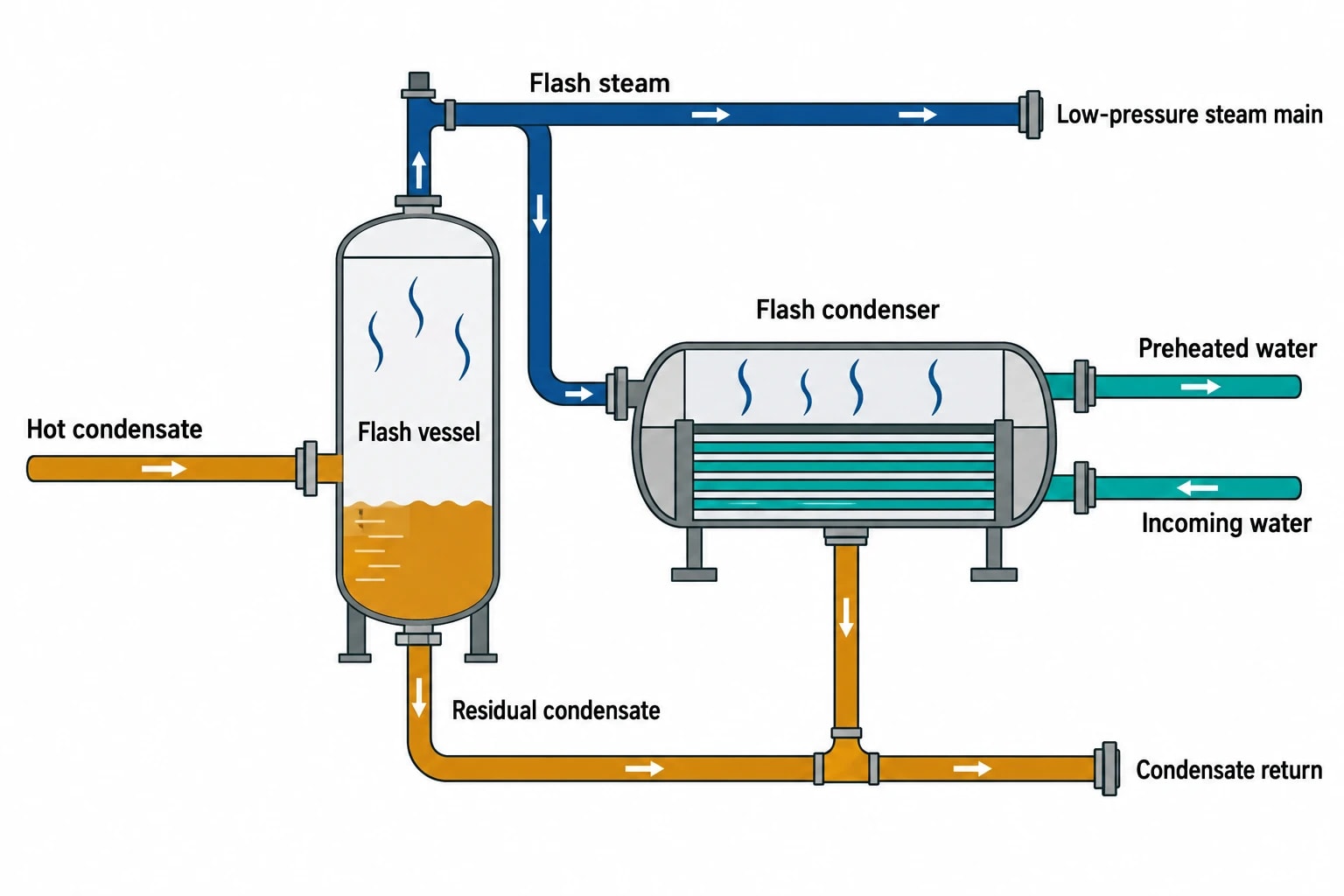
A flash vessel receives hot condensate at lower pressure, allows steam to separate from liquid, and provides distinct outlets for each. Flash steam leaves from the top for use by a low-pressure steam main or heat-recovery exchanger. Residual condensate drains from the bottom through an appropriate arrangement to the return system.
The vessel is not a generic tank. Its design must accommodate expected condensate flow, flashing rate, pressure, separation performance and safe relief arrangements. Undersizing can carry water into the flash-steam line, causing poor heat transfer, waterhammer risk and unstable control. Excessive backpressure can impair condensate drainage from upstream heat exchangers.
A well-conceived installation includes isolation, pressure indication, pressure control, suitable drainage, trapping and safety protection. Pipework needs careful sizing because low-pressure steam has a greater specific volume than high-pressure steam. Long runs may require larger pipework to keep velocity and pressure loss under control.
Choose the right recovery route
Direct use of low-pressure flash steam is efficient where a stable low-pressure process demand exists nearby. A flash condenser may suit plants that need hot water rather than steam. The condenser transfers heat into a segregated water circuit and turns flash vapour back into liquid condensate.
This arrangement can suit food sites where utility water must remain physically separated from the steam and condensate system. It can preheat incoming water ahead of a calorifier or final heating stage. The remaining temperature lift then comes from live steam, reducing the primary steam load.
A flash recovery design should not send recovered condensate or flash steam directly into food or product-contact water without an appropriate process, water-quality and hygiene assessment. Indirect heat transfer keeps the heat-recovery circuit separate from the receiving water circuit and provides a clearer basis for cleanability, inspection and operational control.
Protect production against variable loads
Food plants rarely run at one steady state. Batch cookers start and stop. CIP programmes operate outside core production hours. Product changeovers alter steam demand. A flash system must tolerate these changes without compromising upstream drainage.
Key controls include a live-steam make-up valve for the low-pressure header, a pressure-control strategy that gives flash steam priority, and an engineered route for surplus flash steam. The recovery system must retain a safe pressure path when the receiving process load falls away.
A pressure-reducing valve can supplement the header when flash-steam supply is lower than demand. When flash supply exceeds demand, pressure rises. The installation needs a properly designed response rather than reliance on a safety valve as normal operating control.

Pinch analysis identifies the thermodynamic minimum energy requirement of your process — then designs the heat exchanger network to achieve it.
Pinch Analysis Makes Flash Steam Recovery More Valuable
Treat flash steam as a utility stream
Pinch Analysis sets targets for minimum heating and cooling demand by matching hot and cold process streams according to temperature and heat load. In a food factory, flash steam recovery should sit within that wider heat-integration study.
The key question is not merely, “How much flash steam can the plant create?” It is, “Where can the plant use this heat at the lowest feasible pressure and with the highest annual coincidence of supply and demand?”
That approach prevents poor matches. Using low-pressure steam for a high-temperature duty will fail on driving temperature. Sending flash steam across a large site to a small intermittent user can consume capital and create control problems. Installing a heat exchanger to warm water already heated by another recoverable stream can duplicate equipment while leaving a larger heat source unused.
Build the study around operating cases
A food-factory Pinch Analysis should account for the conditions that determine utility consumption:
| Operating case | Data required | Why it affects flash recovery |
|---|---|---|
| Normal production | Product throughput, steam pressure, condensate flow, water demand | Establishes the main recoverable duty |
| Batch start-up | Timing and peak steam demand | Tests control stability and short peak loads |
| Cleaning cycle | Water flow, target temperature, duration | Identifies potential hot-water heat sinks |
| Reduced production | Minimum process load and boiler turndown | Shows whether demand still matches flash supply |
| Shutdown | Venting, drainage and preservation arrangements | Identifies energy loss and operational constraints |
Site teams should distinguish between high-pressure condensate that can feed a flash vessel and condensate that is contaminated, too variable or unsuitable for return. The former may be a recovery opportunity. The latter may require segregation, treatment or a different heat-recovery route.
A UK starch example points to practical demand
The UK Government's Industrial Heat Recovery Support successful-applicant record lists a Cargill PLC starch operation assessment involving flash steam, plate or shell heat exchangers and process heating. The record frames flash steam as a heat source with an identified end use, rather than as a boiler-house modification in isolation.
Credible projects identify the source, define the receiving duty, establish the temperature approach and calculate the annual overlap. The vessel and pipework follow from the heat balance and operating requirements.
Reliability and Food-Site Risks Must Shape the Design
Avoid waterlogging and heat-exchanger stall
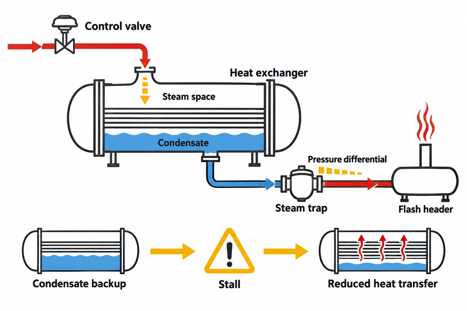
Steam-heated equipment relies on condensate leaving at the rate it forms. If a flash-steam header imposes too much pressure on a trap discharge, condensate can back up into the heat exchanger. Heat transfer can fall, temperature control can hunt and waterhammer risk can increase.
Temperature-controlled heat exchangers require particular care. As a control valve closes, steam-space pressure may fall. If that pressure approaches the flash-header pressure, the available pressure differential across the trap collapses. The system can stall.
Engineers should assess this condition across the operating range, not only at full production load. Solutions can include revised pressure levels, pumped condensate return, different recovery matches or separating equipment with incompatible drainage requirements.
Integrate safety compliance from the outset
A flash vessel and its associated steam pipework form part of a pressure system. Under the Pressure Systems Safety Regulations 2000, Regulation 8 requires the user of an installed system to have a written scheme of examination for relevant parts of the system. The scheme must address protective devices, pressure vessels and pipelines where a defect could give rise to danger.
HSE guidance in INDG436, Safe management of industrial steam and hot water boilers, places boiler safety responsibilities with owners, managers and supervisors. Changes to condensate routing, vessel pressure, protection devices or operating procedures therefore need assessment as part of plant management, not as a simple energy project.
The written scheme, operating limits, relief arrangements, inspection access, isolation procedure and control narrative should reflect the new arrangement before commissioning. Competent persons must determine the required examination scope and intervals.
Measure performance after commissioning
Commissioning should confirm more than steam-header pressure. The team should verify condensate removal from upstream equipment, flash-vessel pressure stability, low-pressure steam temperature, receiver venting, make-up steam demand and the temperature increase on any heated-water circuit.
Useful operating indicators include:
- Flash-vessel pressure against its operating set point.
- Condensate return temperature and flow.
- Live-steam make-up flow to the low-pressure header.
- Venting frequency or vent-condenser duty.
- Upstream heat-exchanger temperature control.
- Boiler fuel use normalised against production.
These measurements show whether recovered heat is displacing live steam or merely moving losses around the steam system.
The Practical Route to Steam System Optimisation in the Food Industry
Flash steam recovery has value because food factories often contain both the source and the demand. High-pressure process condensate carries recoverable heat. Lower-temperature water and steam duties can often accept it. The engineering task is to make those flows meet safely, hygienically and consistently.
Start with a condensate and steam survey. Measure process pressures, trap discharge conditions, production hours and potential low-pressure loads. Use Pinch Analysis to rank competing heat sinks by temperature fit and annual operating overlap. Then develop the vessel, control and return-system design around the selected match.
This article reflects the independent analysis and editorial opinion of EnerTherm Engineering. Product names, trademarks, and brands mentioned belong to their respective owners. EnerTherm Engineering is not affiliated with, endorsed by, or a licensee of any third-party software or product mentioned unless explicitly stated.

Technical Manager — EnerTherm Engineering
John Naranjo is Technical Manager at EnerTherm Engineering, bringing specialist expertise in chemical and environmental engineering. He recently led the implementation of Omni Vision, EnerTherm's real-time energy and utility monitoring platform. He holds an MSc in Environmental Engineering from the University of Huelva and a BSc in Chemical Engineering, with memberships in both the Energy Institute and IChemE.
