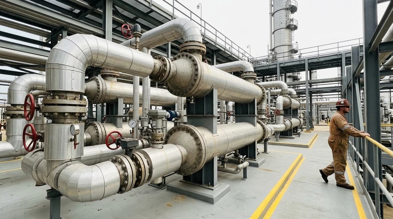
CDU Pinch Analysis Cuts Refinery Emissions by up to 25%
Optimising preheat trains to cut the circa 2% energy consumption of distillation units.
A crude distillation unit pinch analysis is a systematic thermodynamic methodology used to design and optimise heat exchanger networks within refinery preheat trains, maximising process-to-process heat recovery to minimise utility consumption and greenhouse gas emissions. By analysing the thermal profiles of all process streams in a crude distillation unit, this method identifies the physical limits of heat recovery and defines the optimum layout of heat exchangers.
A typical crude distillation unit consumes energy equivalent to approximately 2 per cent of the total crude oil processed, making it the single largest energy consumer in most refineries. Optimising the preheat train and column utilities through process integration directly reduces the fuel burned in fired heaters, cutting site emissions and operating costs.
Defining Crude Distillation Unit Pinch Analysis
Thermodynamic Foundations of Pinch Technology
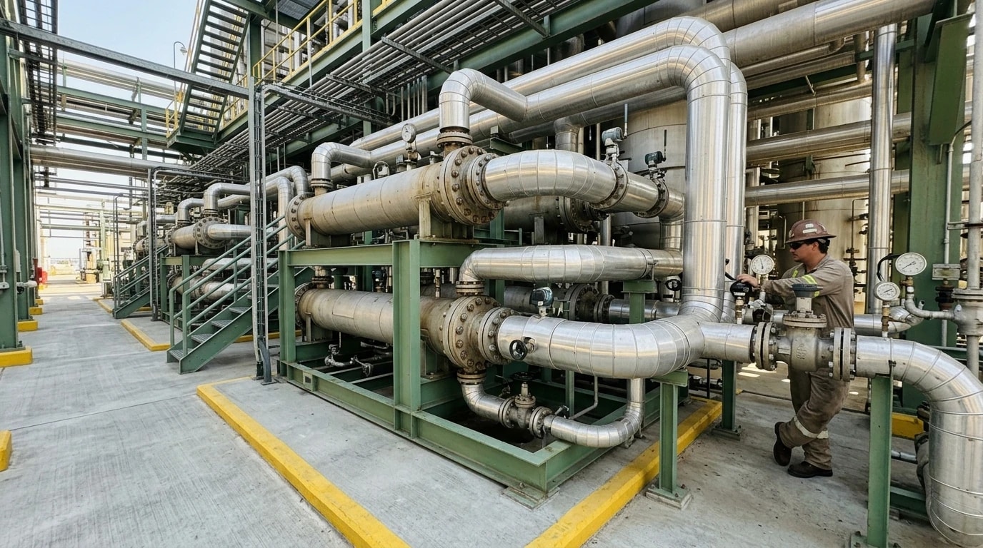
Pinch technology is based on the first and second laws of thermodynamics. The first law ensures total energy conservation, while the second law dictates that heat can only flow spontaneously from a higher-temperature stream to a lower-temperature stream. A crude distillation unit pinch analysis treats the entire preheat train as an integrated system rather than a collection of individual, isolated heat exchangers. By aggregating the heat capacities and temperature intervals of all hot streams (which require cooling) and all cold streams (which require heating), process integration specialists establish the thermodynamic limits of the system.
The Significance of the Pinch Point
The thermodynamic pinch point represents the temperature region where heat transfer is most constrained. It acts as a thermal barrier that divides the crude distillation process into two distinct zones:
- Above the Pinch: This region is heat-deficient, meaning it requires only external heating (hot utility, such as a fired heater) and no external cooling.
- Below the Pinch: This region is in heat surplus, meaning it requires only external cooling (cold utility, such as cooling water or air coolers) and no external heating.
Minimising Cross-Pinch Heat Transfers
The fundamental rule of pinch design is that heat must not be transferred across the pinch point. If heat is transferred from a stream above the pinch to a stream below the pinch, the system incurs a double energy penalty. The hot utility requirement above the pinch increases by the exact amount of heat transferred across the pinch, and the cold utility requirement below the pinch increases by that same amount. Eliminating these cross-pinch heat transfers is the primary mechanism for reducing refinery utility consumption.

Pinch analysis identifies the thermodynamic minimum energy requirement of your process — then designs the heat exchanger network to achieve it.
Thermodynamic Parameters and the Minimum Approach Temperature
Defining the Minimum Approach Temperature
The Minimum Approach Temperature, designated as ΔTmin, is the smallest temperature difference allowed between a hot stream and a cold stream at any point in a heat exchanger. This parameter is a critical design variable in a crude distillation unit pinch analysis because it dictates the driving force for heat transfer. The relationship between heat exchanger surface area, heat load, and temperature driving force is expressed by the standard heat transfer relation:
Q=UAΔTlmWhere:
- Q is the thermal load (kW)
- U is the overall heat transfer coefficient (kW/m²·°C)
- A is the heat exchanger surface area (m²)
- ΔTlm is the logarithmic mean temperature difference (°C)
Balancing Capital Expenditure Against Operating Costs
Selecting the value of ΔTmin involves a direct trade-off between capital expenditure and operating costs.
- Low ΔTmin (e.g. 10°C): Maximises heat recovery, reducing the hot utility load on the fired heater and the cold utility load on the water coolers. However, the lower temperature driving force requires significantly larger heat exchanger surface areas, increasing capital costs for equipment.
- High ΔTmin (e.g. 30°C): Decreases the required heat exchanger surface area, lowering initial capital expenditure. However, it reduces process-to-process heat integration, forcing the refinery to burn more fuel in the fired heater and use more cooling water, leading to higher long-term operating costs.
Process engineers determine the optimum ΔTmin by identifying the minimum point on the Total Annualised Cost curve, which combines annualised capital costs and annual utility costs. For crude distillation units, the optimum ΔTmin typically falls between 15°C and 25°C, depending on prevailing fuel costs and equipment fabrication rates.
Quantifying Utility Savings
Once process engineers select the ΔTmin, they construct the composite curves to determine the minimum energy targets. These targets represent the absolute minimum hot and cold utility duties required to run the process at the chosen ΔTmin. Any utility consumption above these targets indicates inefficiencies, such as poor stream matching or cross-pinch heat transfer in the existing heat exchanger network.
Mapping Complex Process Streams and Pump-Around Circuits
| Stream Name | Stream Type | Supply Temperature (°C) | Target Temperature (°C) | Heat Capacity Flowrate (kW/°C) | Total Enthalpy Change (kW) |
|---|---|---|---|---|---|
| Crude Oil | Cold | 30 | 340 | 120 | 37,200 |
| Column Residue | Hot | 340 | 90 | 90 | 22,500 |
| Pump-Around Loop 1 | Hot | 280 | 210 | 100 | 7,000 |
| Diesel Product | Hot | 250 | 60 | 45 | 8,550 |
| Pump-Around Loop 2 | Hot | 180 | 120 | 80 | 4,800 |
| Kerosene Product | Hot | 190 | 45 | 30 | 4,350 |
| Overhead Vapour | Hot | 130 | 40 | 60 | 5,400 |
Fractionation and Side-Stream Heat Recovery
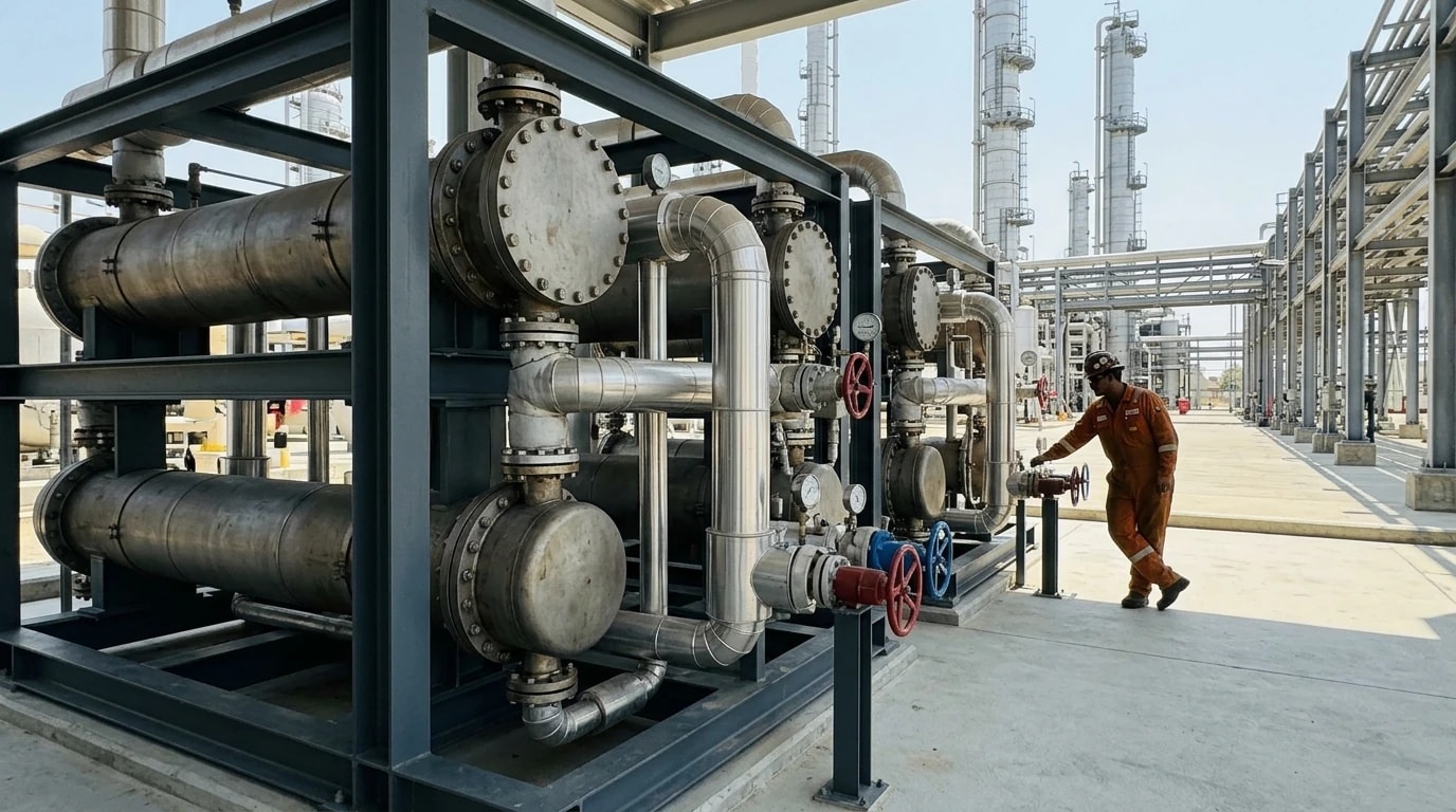
Unlike simple chemical processes, a crude distillation unit features a complex arrangement of side-streams and thermal loops. Fresh crude oil enters the system as a cold stream and must be preheated from ambient storage temperatures to approximately 340°C to 360°C before entering the main distillation column. To achieve this, the crude oil passes through a preheat train where it recovers heat from hot product streams, including naphtha, kerosene, diesel, and gas oil, as well as the heavy column residue. Each of these hot streams has specific temperature limits and heat capacities that must be integrated into the pinch model.
Managing Pump-Around Loops and Thermal Duties
Pump-around circuits are high-volume thermal loops designed to control the vapour and liquid traffic inside the distillation column. Liquid is withdrawn from a specific section of the column, cooled externally by exchanging heat with the incoming crude oil, and then returned to a higher tray.
Pump-around loops act as high-temperature heat sources, making them ideal for preheating cold crude oil. However, their thermal duties are closely linked to the fractionation performance and internal hydraulics of the column. If a pinch analysis suggests increasing the heat recovery from a pump-around loop, process engineers must model the column in a simulator to ensure that the modified heat extraction does not compromise product purity, flood the trays, or stall the internal reflux.
Physical Layout and Safety Constraints
Refinery heat integration must navigate strict structural, layout, and safety constraints. Process streams cannot be matched arbitrarily. High-pressure streams must be kept separate from low-pressure streams in standard shell-and-tube exchangers to prevent catastrophic cross-contamination in the event of a tube rupture.
Furthermore, hot streams containing highly volatile components, such as light naphtha, present severe fire risks and must be matched with safe, stable process sinks. The physical distance between the distillation column and the preheat train also limits heat exchanger placement, as excessive pipe runs introduce high pressure drops, thermal losses, and increased pumping costs.

Pinch analysis identifies the thermodynamic minimum energy requirement of your process — then designs the heat exchanger network to achieve it.
Advanced Simulation Software and Grid Diagrams
Industrial Simulation Platforms
Because of the high number of process streams and the non-linear behaviour of crude oil physical properties, process engineers rely on industrial simulation software to perform crude distillation unit pinch analyses. Dedicated tools process raw temperature and enthalpy data, build composite curves, and automatically calculate energy targets.
Process design teams routinely couple process simulation tools with energy analysis packages to evaluate how heat integration modifications affect overall column yields and preflash drum operations.
Constructing the Heat Exchanger Network Grid Diagram
The heat exchanger network grid diagram is the primary tool used by process integration specialists to design and review thermal networks. In this diagram, hot streams are represented as horizontal lines running from left to right (from high to low temperature), while cold streams run from right to left (from low to high temperature). Vertical lines connecting the hot and cold streams represent individual heat exchangers.
The grid diagram clearly marks the thermodynamic pinch temperature. This visual mapping allows engineers to inspect every heat exchanger in the network and identify pinch violations, such as exchangers operating across the pinch line or cooler units positioned in the high-temperature zone.
Retrofitting Legacy Preheat Trains
Most refineries operating today were constructed before the widespread adoption of modern pinch technology. Consequently, legacy preheat trains often contain significant design inefficiencies, including extensive cross-pinch heat transfers and poorly matched streams.
A retrofit pinch analysis of an existing crude distillation unit focuses on identifying these "culprit" heat exchangers. Once identified, process engineers propose targeted modifications, such as:
- Re-routing existing piping to direct streams to more thermally compatible heat exchangers.
- Adding new heat exchanger shells to increase the heat transfer area in areas where the temperature driving force is low.
- Splitting the cold crude stream into parallel branches to match the heat capacity flowrates of multiple hot product streams, preventing thermal mismatches.
Quantifying Emissions Reductions and Fuel Savings
Achieving Up to 25 Per Cent Carbon Reductions
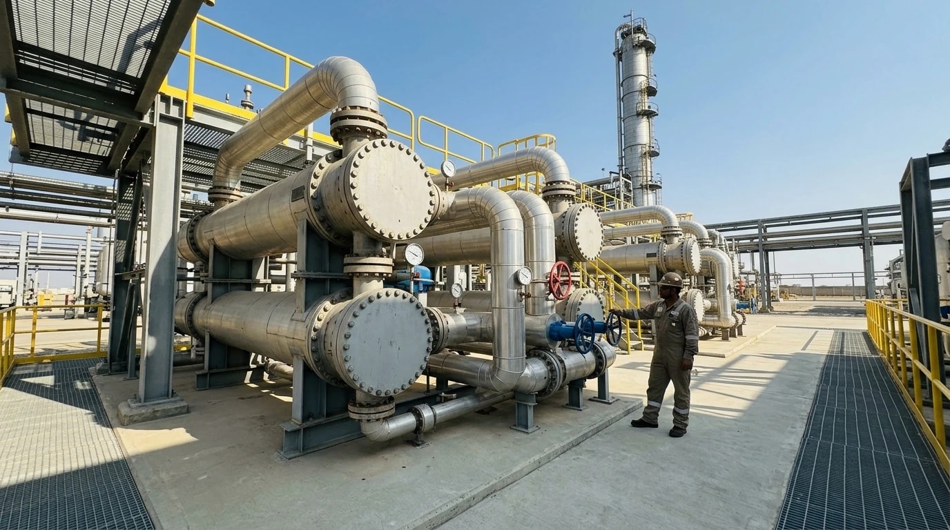
Implementing the results of a crude distillation unit pinch analysis can reduce total refinery greenhouse gas emissions by up to 25 per cent. Because crude distillation is the primary thermal process in a refinery, the carbon footprint of the entire site is heavily influenced by the fuel consumption of the CDU fired heaters.
By maximising heat recovery within the preheat train, the crude oil enters the fired heater at a significantly higher temperature. This reduces the thermal load on the furnace burner, directly lowering the consumption of fuel gas, fuel oil, or natural gas, which in turn reduces Scope 1 carbon dioxide emissions.
Impact on Fired Heaters and Cooling Water Demands
The benefits of process integration extend beyond fuel savings in the primary furnace. Reducing the fired heater duty also lowers the combustion air requirements, which decreases the power consumed by forced-draught and induced-draught combustion fans.
On the cold utility side, recovering more heat within the process streams means that less thermal energy needs to be rejected to the environment. This decreases the thermal load on the refinery cooling water towers and air-cooled heat exchangers. The resulting reduction in cooling water circulation rates saves substantial electricity by lowering the power demand of large water pumps and cooling tower fans.
Real-World Case Studies of Refinery Retrofits
Numerous industrial studies confirm the high returns of crude distillation unit pinch analysis retrofits:
- A Western European Refinery: Integrated process simulation with pinch software to optimise a crude preheat train equipped with a preflash column. The analysis identified several cross-pinch heat exchangers. By re-routing a diesel pump-around stream and adding two heat exchanger shells, the refinery increased the crude preheat temperature by 14°C, reducing furnace fuel consumption and associated carbon emissions.
- An Eastern European Facility: Conducted a comprehensive retrofit analysis of its combined crude and vacuum distillation units. The study identified that the existing network was operating with a high ΔTmin of 32°C. By retrofitting the network to operate at an optimised ΔTmin of 18°C, the plant lowered its hot utility demand, reducing total site carbon emissions and saving millions of dollars in annual energy bills.
Regulatory Compliance and Net-Zero Alignments
The UK Emissions Trading Scheme Framework
Refineries operating in the United Kingdom must comply with the strict requirements of the UK Emissions Trading Scheme (UK ETS), which serves as a central policy instrument for industrial decarbonisation. The UK ETS operates on a cap-and-trade principle, where the absolute cap on allowable greenhouse gas emissions declines each year to align with the UK statutory target of reaching net-zero emissions by 2050.
Refinery operators are required to monitor, report, and surrender tradable carbon allowances equivalent to their annual verified emissions. Implementing a crude distillation unit pinch analysis directly lowers Scope 1 emissions, reducing the number of carbon allowances a refinery must purchase on the market and mitigating compliance costs.
European Industrial Emissions Directive and BAT Standards
In Europe, industrial facilities are governed by the European Industrial Emissions Directive (Directive 2010/75/EU). Under this directive, environmental permits are based on Best Available Techniques (BAT) Reference Documents (BREFs). The BREF for the Refining of Mineral Oil and Gas (REF BREF) specifically mandates high levels of energy efficiency and continuous thermal integration.
The legally binding BAT conclusions state that refiners must implement structured environmental management systems and deploy process integration methodologies, such as pinch analysis, to minimise energy consumption and air emissions. Failure to align preheat train designs with these BAT standards can lead to the withholding or revocation of operating permits by national environmental regulators.
Navigating Carbon Taxes and Environmental Permits
The regulatory pressure on refiners will intensify with the introduction of the UK Carbon Border Adjustment Mechanism (CBAM), scheduled to take effect on 1 January 2027. The UK CBAM will apply a carbon price to import-intensive products, ensuring that domestic industries investing in decarbonisation are not disadvantaged by high-carbon imports.
To maintain international competitiveness under this changing trade regime, UK and European refiners must aggressively drive down the carbon intensity of their products. Optimising heat exchanger networks through crude distillation unit pinch analysis is one of the most cost-effective engineering strategies available, delivering rapid carbon reductions while improving the refinery bottom line.
This article reflects the independent analysis and editorial opinion of EnerTherm Engineering. Product names, trademarks, and brands mentioned belong to their respective owners. EnerTherm Engineering is not affiliated with, endorsed by, or a licensee of any third-party software or product mentioned unless explicitly stated.

Managing Director — EnerTherm Engineering
Dr. François Pierrel is Managing Director of EnerTherm Engineering with over two decades of expertise in thermal design, heat transfer, and industrial energy optimisation. He holds a PhD in Heat Transfer from Cranfield University and a Post-Doctorate from Heriot-Watt University.
