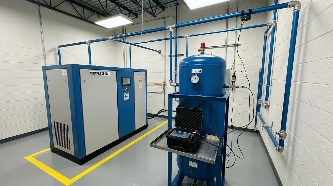
compressed air energy audit
A compressed air energy audit is a systematic engineering assessment designed to map flow rates, measure power consumption, identify system leaks, and evaluate the overall efficiency of an industrial pneumatic network. A professional assessment goes beyond a basic leak patrol by investigating the generation, treatment, distribution, and demand sides of a compressed air system. This process locates supply-demand imbalances, identifies pressure drops, and determines the exact electrical energy cost of generating each cubic metre of compressed air.
In the UK food and beverage sector, where facilities cope with high electricity tariffs of 28p to 32p per kWh, compressed air systems are primary targets for energy reduction. Compressors are energy-intensive utilities, and pneumatic applications often consume up to 20% to 30% of a factory's total electricity. A comprehensive audit provides the analytical foundation needed to minimise this utility expenditure without compromising production hygiene or safety.
What is a Compressed Air Energy Audit?
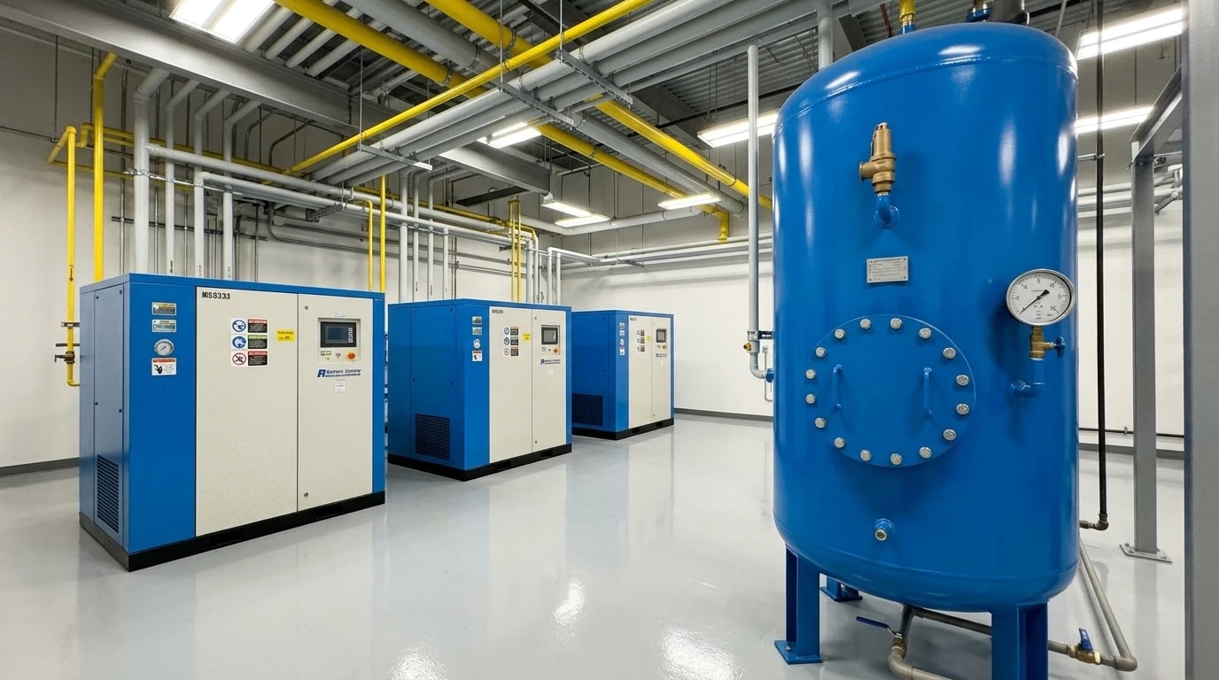
A compressed air energy audit establishes a precise baseline of pneumatic energy consumption and system performance, revealing exactly where energy is wasted and how to improve overall efficiency.
Defining the Scope of Assessment
An effective assessment evaluates how efficiently a compressor station converts electrical energy into pneumatic energy. It tracks parameters such as compressor specific power, which measures the electrical power required (in kilowatts) to deliver a specific volume of air (expressed as kilowatts per cubic metre per minute). The audit also examines whether the current treatment equipment, including refrigerant dryers, desiccant dryers, and coalescing filters, is appropriately sized or causing excessive pressure drops that force the compressors to run at unnecessarily high pressures.
Subsystems Covered under ISO 11011
Standard auditing frameworks break the industrial compressed air system down into three distinct functional subsystems:
- The supply subsystem: This includes the compressors, primary receivers, and air treatment devices such as dryers and filters.
- The transmission subsystem: This comprises the distribution pipework network, secondary receivers, and filtration units.
- The demand subsystem: This encompasses all pneumatic actuators, product blow-offs, control valves, and end-use applications.
Auditing across all three subsystems ensures that efficiency gains on the generation side are not negated by downstream waste.

Identify where your plant is losing energy and quantify the savings potential — our audits map every heat source, sink, and waste stream in your facility.
The Regulatory Framework: BS EN ISO 11011:2015 and Food Safety Compliance
Assessments in the food and beverage sector must comply with national and international standards to guarantee both energy efficiency and food safety.
Standardising Assessments with BS EN ISO 11011:2015
The primary standard governing this discipline is BS EN ISO 11011:2015. This British and international standard sets out the formal requirements for conducting and reporting the results of a compressed air system energy efficiency assessment. It establishes a uniform methodology for gathering data, analysing system behaviour, estimating potential energy savings, and documenting the final findings. Following this standard ensures that the audit data is transparent, reliable, and capable of supporting complex capital investment decisions.
Managing Contamination Risks with BCAS Best Practice Guide 102
In food and beverage processing, utility managers must balance energy reductions with strict hygienic compliance. The British Compressed Air Society (BCAS) publishes Best Practice Guide 102 ('Food and Beverage Grade Compressed Air'), which outlines the critical quality requirements for compressed air when it is used in proximity to ingredients or packaging. This guide helps processors manage hazards under their Hazard Analysis and Critical Control Point (HACCP) frameworks, ensuring that pneumatic utilities do not introduce particulates, moisture, or microbial contamination into hygienic production lines.
Achieving ISO 8573-1 Class 0 for Oil-Free Hygienic Zones
A key element of BCAS Best Practice Guide 102 is the division of compressed air applications into direct-contact and non-contact zones. For compressed air that comes into direct contact with food or packaging, the guide recommends meeting the stringent purity standards of ISO 8573-1 Class 0 for total oil concentration. Class 0 requires that oil contamination (including aerosols, liquids, and vapours) remains significantly below the Class 1 threshold of 0.01 mg/m³.
The guide suggests specific purity classes depending on the contact type:
- Direct Contact (Class 2:2:1):
- Particles (Class 2): No more than 400,000 particles per m³ in the 0.1 to 0.5 µm range, and 6,000 particles in the 0.5 to 1.0 µm range.
- Water (Class 2): A pressure dew point of -40 °C or lower.
- Oil (Class 1): Total oil concentration must not exceed 0.01 mg/m³.
- Indirect Contact (Class 2:4:2):
- Particles (Class 2): Same particulate limits as direct contact.
- Water (Class 4): A pressure dew point of +3 °C or lower.
- Oil (Class 2): Total oil concentration must not exceed 0.1 mg/m³.
Auditors must verify that any energy-saving equipment retrofitted to these systems maintains these critical compliance levels to prevent contamination risks.
The Financial and Environmental Cost of Compressed Air Leaks
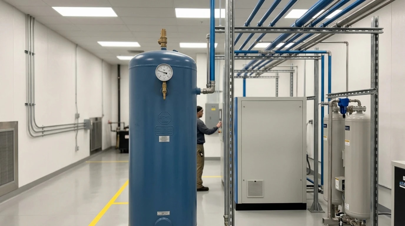
Pneumatic systems in typical, unaudited industrial factories lose between 10% and 30% of their generated compressed air to leaks. Because air leaks are silent and invisible, they often go unnoticed in busy, high-noise processing environments.
Translating Air Waste into Pounds and Tonnes of CO₂
At current UK industrial electricity rates, even a single 3.0 mm leak at 7 bar of operating pressure can waste approximately £2,448 per year in electricity, which is equivalent to emitting 5.2 tonnes of CO₂ into the atmosphere. This cost is driven by the fact that compressed air is an inefficient medium to generate, with only about 10% to 15% of the electrical energy input converted into useful pneumatic work at the point of use.
Estimated Annual Leak Waste Matrix
The financial and environmental impact of pneumatic leakage scales exponentially with orifice size and operating pressure. The table below outlines typical annual losses for a plant operating at a standard 7 bar system pressure with an electricity tariff of 30p per kWh and 6,000 annual running hours, assuming a compressor specific power of 7.0 kW per m³/min.
| Leak Hole Diameter (mm) | Approximate Flow Loss (L/s) | Power Wasted (kW) | Annual Energy Wasted (kWh) | Annual Cost (£) | Carbon Footprint (tonnes CO₂e) |
|---|---|---|---|---|---|
| 1.0 mm (Pinhole) | 1.0 | 0.15 | 900 | £270 | 0.6 |
| 2.0 mm (Small Fitting) | 4.0 | 0.60 | 3,600 | £1,080 | 2.3 |
| 3.0 mm (Coupling Leak) | 9.1 | 1.36 | 8,160 | £2,448 | 5.2 |
| 5.0 mm (Worn Gasket) | 25.2 | 3.78 | 22,680 | £6,804 | 14.5 |
| 10.0 mm (Open Valve) | 100.8 | 15.12 | 90,720 | £27,216 | 58.1 |
Calculations are based on choked flow conditions under ISO 6358 standards. Actual costs may vary depending on local tariffs and plant-specific compressor efficiencies.
The Secondary Operational Costs of Air Loss
The cost of compressed air leakage extends beyond direct electricity waste. When leaks drain pressure from the transmission lines, the overall system pressure drops. To compensate, operators often raise the compressor pressure setpoint. However, raising the system pressure by just 1 bar increases overall compressor energy consumption by approximately 7%. Furthermore, leaks force compressors to run on longer duty cycles, accelerating component wear, increasing maintenance intervals, and raising the risk of unexpected production downtime.
EnerTherm’s 7-Step Methodology for Compressed Air Audits
At EnerTherm Engineering, compressed air energy audits are positioned within a broader, integrated approach to industrial utility and thermal efficiency. Food and beverage plants consume massive amounts of thermal energy for processes such as bakery ovens, tunnel dryers, fryers, and steam systems (used in Clean-in-Place (CIP) cleaning, cooking, and pasteurisation). Because pneumatic systems generate large amounts of heat during compression, an effective audit must link the compressed air network with these thermal processes to identify heat recovery opportunities.
Step-by-Step Execution of the Audit Framework
EnerTherm's structured auditing framework utilises a 7-step methodology to identify, analyse, and eliminate compressed air waste without disrupting the food safety or operational schedules of the processing plant.
- Initial Consultation: Defining the boundaries of the audit, reviewing historical utility bills, and identifying high-hygiene zones or critical control points.
- On-Site Assessment: Conducting non-invasive measurements and leak detection during active production hours using portable, calibrated instrumentation.
- Data Analysis: Evaluating flow rates, pressure fluctuations, compressor power curves, and leak volumes to establish an operational baseline.
- Opportunity Identification: Developing specific, costed recommendations, ranging from simple leak sealing to thermal heat recovery and compressor upgrades.
- Report Preparation: Producing a board-ready report detailing energy savings, carbon reductions, and financial metrics (such as payback period, NPV, and IRR).
- Implementation Support: Assisting the facility's maintenance staff or external contractors with repairs, system balancing, and equipment configuration.
- Ongoing Measurement and Verification (IPMVP): Employing the International Performance Measurement and Verification Protocol (IPMVP) to prove and sustain energy savings over time.

Identify where your plant is losing energy and quantify the savings potential — our audits map every heat source, sink, and waste stream in your facility.
On-Site Audit Technologies: Ultrasonic Detection and Non-Invasive Data Logging
Hygienic audits require highly accurate data collection without risking contamination or forcing production shutdowns.
Non-Invasive Portable Instrumentation
Modern audits rely on portable, non-invasive instrumentation. Clamp-on, non-intrusive power analysers are placed on the compressor's electrical supply to log true power draw (kW) and power factor over a representative seven-day production cycle. Insertion-type or thermal mass flow meters are fitted into existing port openings to measure actual system air demand (m³/min) alongside pressure transducers that track pressure fluctuations across the transmission line.
Ultrasonic Leak Detection in Hygienic Processing Zones
Because food factories are high-noise environments, maintenance personnel cannot hear air leaks with the naked ear. Industry professionals widely regard ultrasonic leak detection as the standard method for locating pneumatic waste. These portable instruments detect the high-frequency acoustic waves (typically between 35 kHz and 40 kHz) generated by turbulent airflow escaping from a leak.
The ultrasonic detector converts these high-frequency sounds into audible frequencies (a process known as heterodyning) and displays the decibel level or a visual representation on a screen. Because ultrasound is highly directional, auditors can pinpoint the exact location of a leak from several metres away, even in a noisy bottling or packaging hall. This process requires zero contact with production equipment, keeping hygienic zones completely uncontaminated.
Furthermore, industry professionals often use sophisticated acoustic imaging cameras. These cameras combine an array of highly sensitive microphones with a standard optical camera to overlay a colour-coded map of the leak onto a live video feed. This allows technicians to spot leaks on high-overhead piping runs or in restricted-access areas without needing to climb ladders or shut down production lines.
Thermal Imaging for Compressor Heat Loss
In addition to ultrasonic tools, thermal imaging cameras are deployed during the on-site assessment. Thermography identifies localised hot spots on compressors, indicating worn valves, blocked coolers, or failing motor bearings. More importantly, thermal imaging maps the temperature profiles of the compressor head and cooling circuits to evaluate whether the heat rejected during the compression process can be recovered and diverted to other facility utilities.
Technical Solutions for Energy Optimisation in Food and Beverage Plants
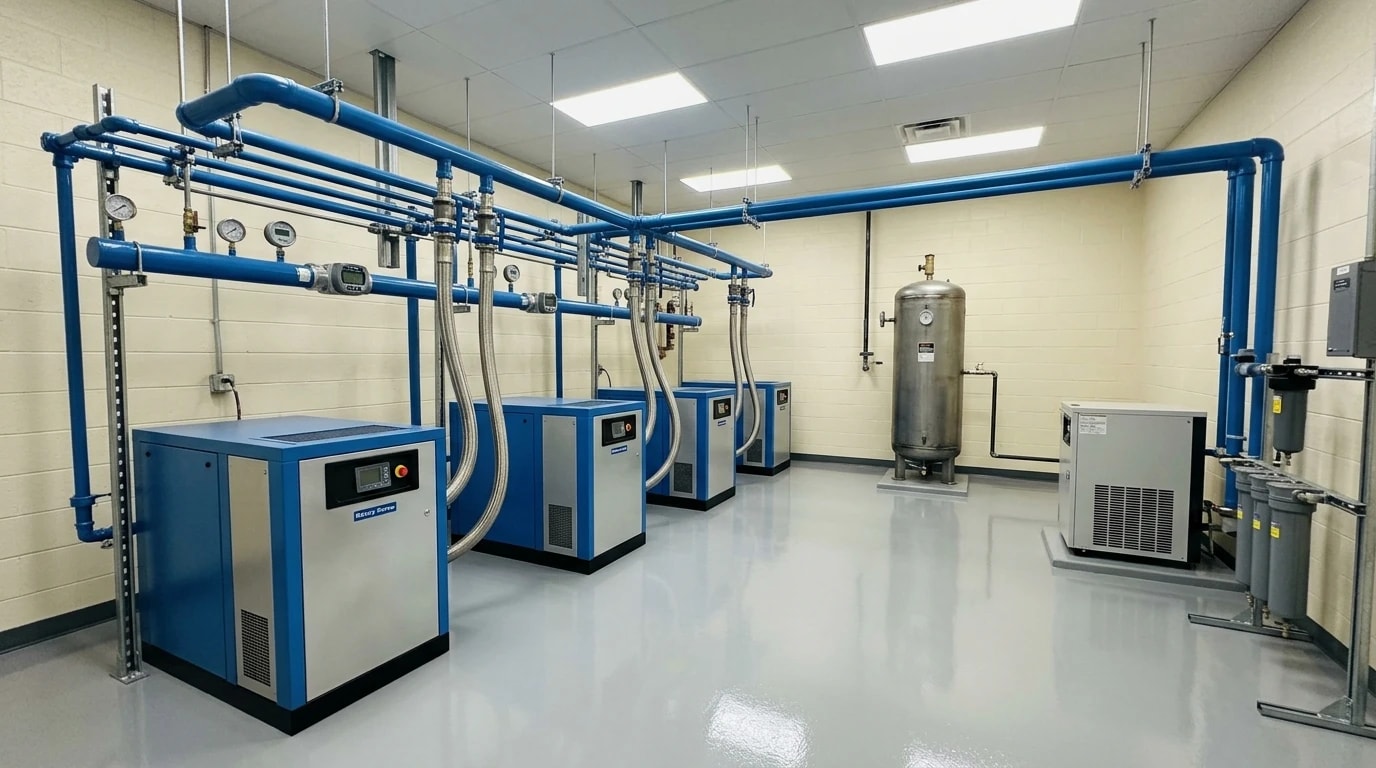
After identifying areas of waste, facilities can deploy several technical solutions to optimise system efficiency.
Variable-Speed Drive (VSD) Integration
Many food processing lines experience variable pneumatic demands. For instance, packaging and bottling lines run at varying speeds depending on the product run, leading to significant fluctuations in compressed air demand. Fixed-speed compressors are inefficient when operating under partial loads, as they must unload and run idle while still consuming up to 30% to 40% of their full-load power.
Integrating a variable-speed drive (VSD) compressor into the supply subsystem allows the system to match generation closely with actual demand. The VSD dynamically alters the speed of the compressor motor in response to pressure changes, keeping system pressure stable and eliminating idle running losses. On average, upgrading to a VSD compressor can reduce compressor energy consumption by 15% to 25% in facilities with variable demands.
Additionally, when multiple compressors are present, the audit may recommend a master controller or sequencing system. The sequencing system ensures that only one VSD compressor modulates to handle fluctuating loads, while the remaining fixed-speed compressors either run at 100% full load (their peak efficiency point) or remain completely shut off.
High-Efficiency Waste Heat Recovery Systems
Up to 90% of the electrical energy supplied to an industrial air compressor is converted directly into heat. In many standard installations, this heat is simply rejected into the atmosphere via air coolers or cooling towers. However, in food and beverage plants, there is a constant demand for thermal energy.
By installing a compressor heat recovery system, process engineers can capture this thermal energy using water-cooled heat exchangers. The recovered heat can be used to:
- Preheat boiler feed water for steam generation systems.
- Supply hot water to washdown or Clean-in-Place (CIP) systems, reducing gas or steam usage.
- Provide space heating or preheat air for tunnel dryers and baking ovens.
This integration bridges the gap between the pneumatic and thermal utilities, turning a major source of waste into a valuable resource.
Pressure Optimisation and System Separation
Another straightforward optimisation is lowering the operating pressure of the system. Many facilities run their entire compressed air network at an elevated pressure (such as 8.5 bar) simply to satisfy a single, high-pressure machine or process.
A thorough audit can identify these high-pressure demands and separate them from the rest of the facility. By installing localised pressure boosters for the few machines that require high pressure, the pressure of the main distribution header can be safely lowered (such as to 6.5 bar). Since every 1 bar reduction in system pressure yields a 7% reduction in compressor energy usage, this separation can lead to major, long-term savings.
Building a Board-Ready Investment Case
Securing capital approval for major utility upgrades requires a robust financial case; simple payback calculations are rarely enough for board-level sign-off.
Financial Modelling via NPV and IRR
Professional audit reports provide detailed financial projections using:
- Net Present Value (NPV): Demonstrating the long-term value generated by the investment over the lifetime of the new equipment, accounting for the time value of money.
- Internal Rate of Return (IRR): Providing a percentage return that can be compared directly with other potential business investments.
- Payback Analysis: Outlining the precise month in which the accumulated energy savings will fully offset the initial capital cost.
By presenting these standard financial metrics, managers can transform a technical efficiency proposal into a compelling, low-risk business case.
Aligning Audits with Carbon Net Zero Roadmaps
With the UK committed to achieving Net Zero greenhouse gas emissions by 2050, UK manufacturers must actively reduce their carbon footprints. Because compressed air is so electricity-intensive, reducing pneumatic waste is one of the fastest and most cost-effective ways to cut Scope 2 emissions.
Implementing the findings of a compressed air energy audit typically helps food and beverage plants achieve an 18% energy cost reduction alongside an average 850-tonne annual CO₂ reduction, aligning operational savings directly with corporate sustainability targets.
This article reflects the independent analysis and editorial opinion of EnerTherm Engineering. Product names, trademarks, and brands mentioned belong to their respective owners. EnerTherm Engineering is not affiliated with, endorsed by, or a licensee of any third-party software or product mentioned unless explicitly stated.

Technical Manager — EnerTherm Engineering
John Naranjo is Technical Manager at EnerTherm Engineering, bringing specialist expertise in chemical and environmental engineering. He recently led the implementation of Omni Vision, EnerTherm's real-time energy and utility monitoring platform. He holds an MSc in Environmental Engineering from the University of Huelva and a BSc in Chemical Engineering, with memberships in both the Energy Institute and IChemE.
