Effluent Heat Recovery Cuts Dyeing Costs by up to 63.2%
Preheating freshwater to 65°C using waste effluent to secure a payback under 1.8 years.
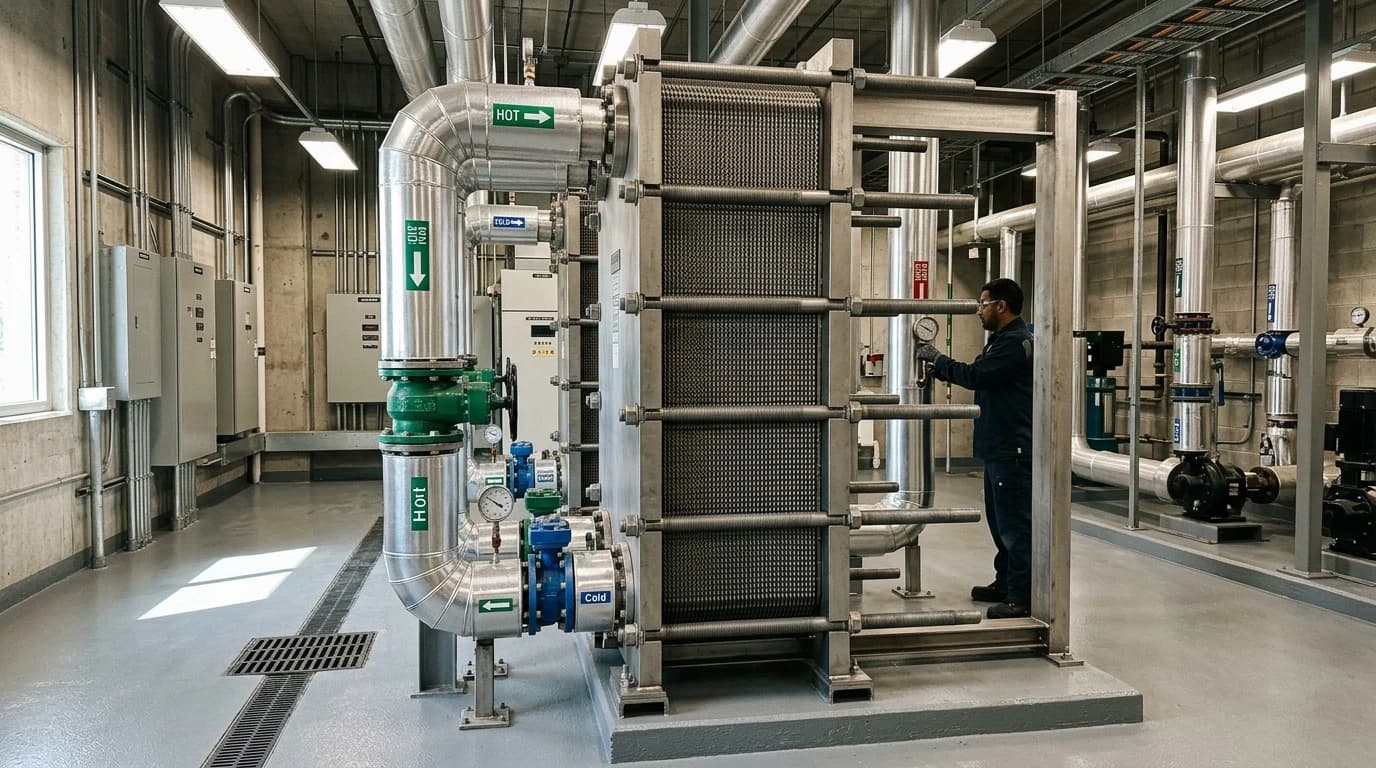
Effluent heat recovery in textile wet processing is a thermal engineering method that captures waste heat from hot wastewater and transfers it to incoming freshwater to improve textile dyeing process energy efficiency. By recovering energy that would otherwise be discharged into sewers or the environment, industrial wet processing facilities can lower their primary boiler fuel demand. Detailed thermodynamic and economic modelling demonstrates that utilising wastewater streams above a lower-limit temperature threshold of 40°C balances heat quality and quantity, resulting in up to a 63.2% reduction in operational heating costs compared to unrecovered baselines.
Understanding Textile Dyeing Process Energy Efficiency and Waste Heat
Thermal Energy Demands in Dye Houses
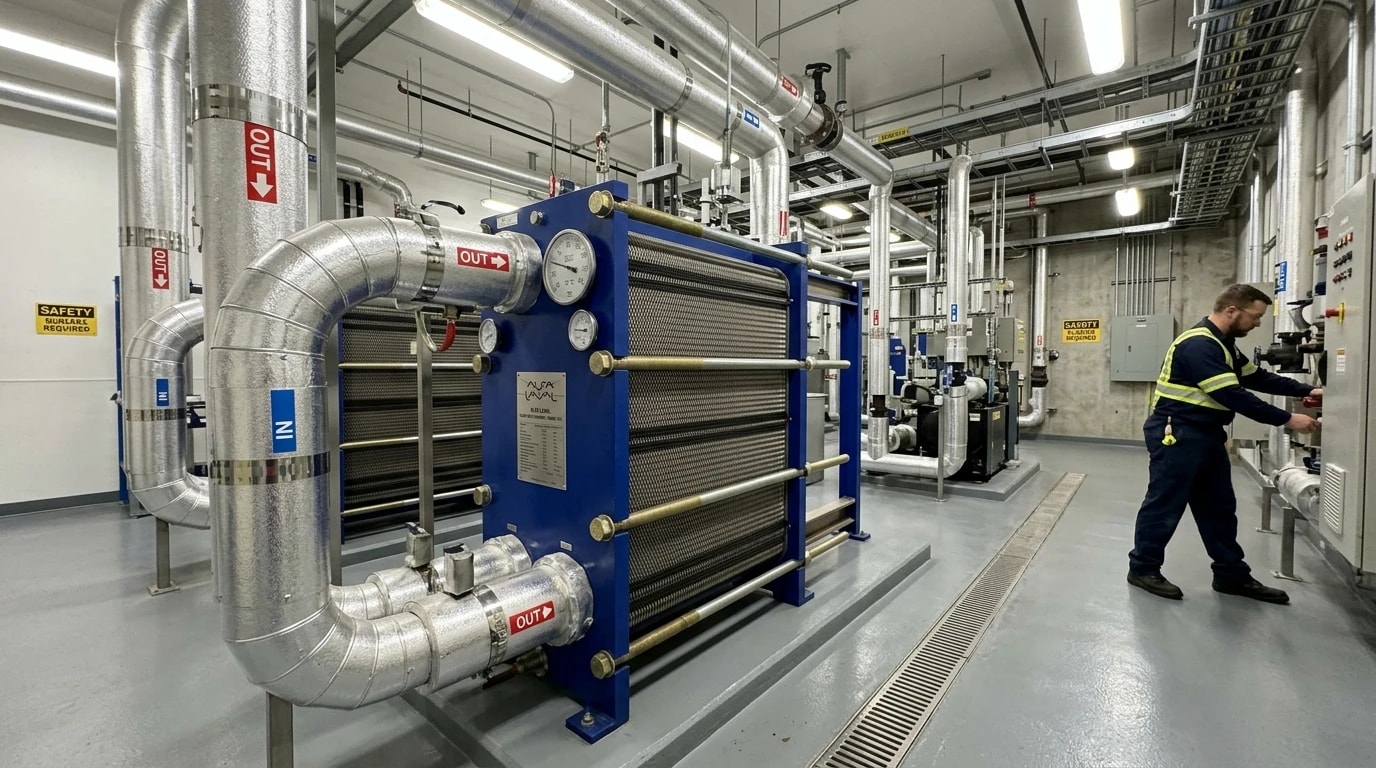
Textile wet processing facilities consume vast quantities of thermal energy, primarily in the form of steam and high-temperature water. This intensive energy consumption is driven by the necessity to heat process baths to specific chemical activation thresholds. Fabric preparation, scouring, bleaching, dyeing, and washing stages require process water temperatures to be precisely controlled between 60°C and 95°C. In a typical finishing facility, heating these baths accounts for up to 60% of the total plant energy demand. Generating this thermal energy requires continuous boiler operation, which consumes fossil fuels such as natural gas, oil, or coal, contributing directly to the facility's Scope 1 carbon footprint.
To maintain the precise temperature profiles required for high-quality dye fixation and shade consistency, boilers must supply steam directly or through secondary heat exchangers to the dye vats. Once a specific batch process completes, the dye-bath liquid is discharged as wastewater effluent.
The Wastewater Energy Disconnect
When dye baths are discharged, they carry a high thermal load, with effluent temperatures usually ranging between 60°C and 80°C. Standard practices at unoptimised facilities involve discharging this hot wastewater directly to the effluent treatment plant (ETP) or municipal sewers. Direct discharge of hot wastewater represents a double loss. First, the thermal energy purchased in the form of boiler fuel is lost. Second, municipal regulations and biological ETP processes often impose strict temperature limits, usually requiring wastewater to be cooled below 35°C or 40°C before disposal or treatment to protect biological bacteria and pipe integrity. Consequently, plants must spend additional energy on cooling towers or retention ponds to lower the temperature of the effluent before treatment.
Bridging this gap requires an integrated approach to thermal management, where waste energy from the outgoing stream is directly transferred to preheat incoming freshwater. By capturing this energy, dye houses can significantly improve textile dyeing process energy efficiency and reduce the thermal load on their steam boilers.

Identify where your plant is losing energy and quantify the savings potential — our audits map every heat source, sink, and waste stream in your facility.
Thermodynamic Modelling: Why the 40°C Threshold is Optimal
Balancing Heat Quality and Quantity
Not all waste heat in a dye house is equal. The ease of recovering energy depends on both the temperature (heat quality) and the volume (heat quantity) of the wastewater stream. Wastewater streams discharged at higher temperatures are easier to recover heat from, but they represent a smaller total volume. Conversely, lower-temperature streams provide larger volumes of water but offer a lower thermal gradient, making the heat transfer less effective and requiring larger, more expensive heat exchangers.
To determine the most efficient operating window, process engineers utilise pinch analysis and detailed thermodynamic modelling of integrated heat recovery systems. This modelling evaluates the lower-limit temperature threshold of the wastewater stream that should be directed to the heat recovery system.
Modelling Findings: Case 1, 2, and 3 Comparisons
Industrial research published in Applied Thermal Engineering analysed three distinct operational scenarios for a single-exchanger, single-tank integrated heat recovery system:
- Case 1: Directing only wastewater above a lower-limit threshold of 50°C to the heat recovery system. This scenario offers high-quality heat but captures a limited volume of water, leaving significant energy unrecovered in the drainage.
- Case 2: Directing wastewater above a lower-limit threshold of 40°C. This configuration captures a substantial volume of wastewater while maintaining a high enough temperature differential to preheat freshwater efficiently.
- Case 3: Directing all wastewater above a lower-limit threshold of 30°C. While this captures the largest volume, the low thermal gradient decreases heat transfer efficiency and increases the required heat exchanger surface area, while also risking overcooling the stream and causing condensation issues.
The thermodynamic and economic modelling showed that Case 2 provides the ideal balance. It achieves the lowest heat demand of 795.5 kW and eliminates heat loss through the drainage. Most importantly, the economic analysis verified that utilising a lower-limit threshold of 40°C reduces operational heating costs by up to 63.2% compared to an unrecovered baseline.
The table below summarises the thermodynamic and economic performance of these three heat recovery thresholds compared to an unrecovered base case:
| Performance Metric | Base Case (No Recovery) | Case 1 (> 50°C) | Case 2 (> 40°C) | Case 3 (> 30°C) |
|---|---|---|---|---|
| Lower Temperature Threshold (°C) | N/A | 50.0 | 40.0 | 30.0 |
| Process Heat Demand (kW) | 2,160.0 | 950.0 | 795.5 | 880.0 |
| Operational Heating Cost Reduction (%) | Baseline | 54.1 | 63.2 | 59.3 |
| Drainage Thermal Loss | High | Medium | Zero | Low |
| Required Heat Exchanger Area | N/A | Small | Medium | Large |
Selecting and Designing Wide-Gap Plate Heat Exchangers for Textile Effluent
Overcoming Clogging from Fibres and Lint
Textile dyeing wastewater is not clean water. It contains a high concentration of suspended solids, loose fibres, lint, processing chemicals, and unfixed dyes. Standard gasketed plate heat exchangers have narrow channel spacings (typically between 2 mm and 4 mm) and contact points between the plates that easily trap fibres, leading to rapid clogging, fouling, and dramatic pressure drops.
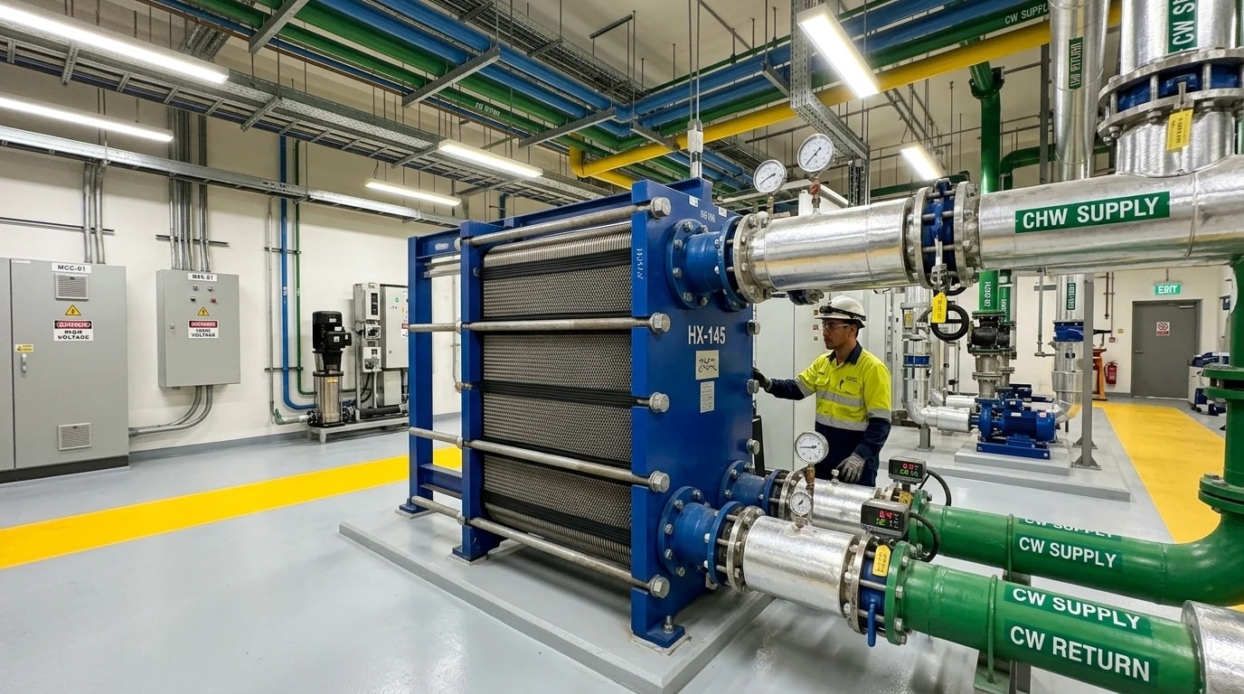
To ensure reliable operation without constant maintenance downtime, thermal design teams typically select specialised wide-gap plate heat exchangers. These wide-gap designs feature channel spacings ranging from 5 mm to 24 mm. The plates are pressed with deep, smooth contours that eliminate traditional contact points where fibres could accumulate. This specialised geometry allows suspended solids and fibres up to 10 mm in length to pass through the channels without sticking, maintaining turbulent flow and high heat transfer coefficients.
Corrosion Resistance and Gasket Materials
The chemical makeup of dye house effluent is highly aggressive, often featuring extreme pH levels, strong bleaching agents, and high salinity. Standard carbon steels or low-grade stainless steels fail rapidly due to localised pitting and stress corrosion cracking. To withstand these conditions, wide-gap plate heat exchangers are constructed using high-grade corrosion-resistant alloys, such as Grade 316L stainless steel, or titanium for processes involving high chloride concentrations.
Gasket materials must be selected based on both temperature and chemical compatibility. Ethylene propylene diene monomer (EPDM) gaskets are widely used due to their excellent resistance to high temperatures (up to 150°C) and the organic chemicals, acids, and alkalis typically found in textile processing. For fully-welded or semi-welded wide-gap designs, gaskets are eliminated on the aggressive wastewater side, with laser-welded plate pairs containing the effluent.
Continuous Flow vs. Single-Tank Integrated Storage Configurations
Dye houses operate on a mixture of continuous and batch processes. Continuous processing machines, such as open-width washers or continuous bleaching ranges, discharge a steady flow of hot effluent, making direct continuous heat exchange straightforward. In contrast, batch dyeing machines (such as jet or overflow machines) discharge large volumes of hot wastewater in short, intermittent bursts.
To handle batch discharges, thermal design teams integrate storage systems to decouple the effluent discharge from the freshwater supply. Two primary configurations are used:
- Continuous Multi-Exchanger System: Multiple smaller heat exchangers are installed directly at individual machines, preheating freshwater locally. This configuration requires a complex network of piping and valves but allows direct heat transfer.
- Single-Tank/Single-Exchanger Integrated Storage System: Hot effluent from all batch machines is collected in a centralised insulated storage tank. The effluent is pumped at a controlled, continuous rate through a single wide-gap plate heat exchanger, preheating incoming fresh water which is then stored in an insulated freshwater tank. This configuration has a small physical footprint, simplifies maintenance, and provides a buffer that ensures a steady supply of preheated freshwater to the dye house.
Thermodynamic Calculations of Heat Recovery Potential
Thermal Power Equation and Flow Rates
To accurately design a heat recovery system, process engineers must calculate the thermal power available within the waste effluent stream. This potential is determined by the mass flow rate, the specific heat capacity of the water, and the usable temperature differential. The recovered thermal power is calculated using the following thermodynamic formula:
Q=m˙⋅Cp⋅ΔTwhere:
- Q is the recovered thermal power in kilowatts (kW)
- m˙ is the mass flow rate of the effluent stream in kilograms per second (kg/s)
- Cp is the specific heat capacity of water, which is approximately 4.186 kJ/kg·°C
- ΔT is the temperature change of the effluent stream across the wide-gap heat exchanger in degrees Celsius (°C)
For example, if a dye house discharges hot wastewater at a flow rate of 10 litres per second (which equates to a mass flow rate of approximately 10 kg/s) at 75°C, and the heat exchanger cools this effluent down to 35°C before discharge to the sewer, the temperature change ΔT is 40°C. Applying the formula:
Q=10⋅4.186⋅40=1,674.4 kWThis calculation demonstrates that over 1.6 megawatts of thermal power can be continuously recovered. This captured energy is transferred directly to the incoming cold freshwater supply. If the fresh mains water enters the facility at 15°C, this recovered thermal power can preheat the water up to 65°C before it reaches the boiler or direct steam-heating lines. Consequently, the steam boiler only needs to supply the energy required to raise the water from 65°C to the final process temperature (e.g., 90°C), reducing the boiler's heating load by more than 60%.

Identify where your plant is losing energy and quantify the savings potential — our audits map every heat source, sink, and waste stream in your facility.
System Architecture: Integrated Heat Recovery and Supply
Single-Tank and Single-Exchanger Design Flow
The physical layout of existing dye houses is often highly constrained, with limited free floor space for large equipment installations. A single-tank and single-exchanger integrated storage setup solves this constraint by minimising the number of auxiliary components. In this configuration, the freshwater itself is used as the primary thermal carrier.
Hot wastewater from the dyeing vats is directed to a collection pit, which acts as a preliminary screen for large particles. From there, it is pumped through the wide-gap plate heat exchanger. At the same time, cold mains freshwater is pumped in a counter-current direction through the other side of the exchanger, where it absorbs the thermal energy and is heated to 65°C. This heated freshwater is then stored in an insulated thermal buffer tank, ready to be drawn as needed for the next dyeing cycle.
The diagram below illustrates the process flow of a centralised single-tank, single-exchanger heat recovery system:
This simplified configuration ensures that the heat exchanger runs continuously at its optimum thermal efficiency, avoiding the rapid cycling and thermal stresses associated with direct batch heating.
Implementing Dye House Energy Audits with EnerTherm’s 7-Step Methodology
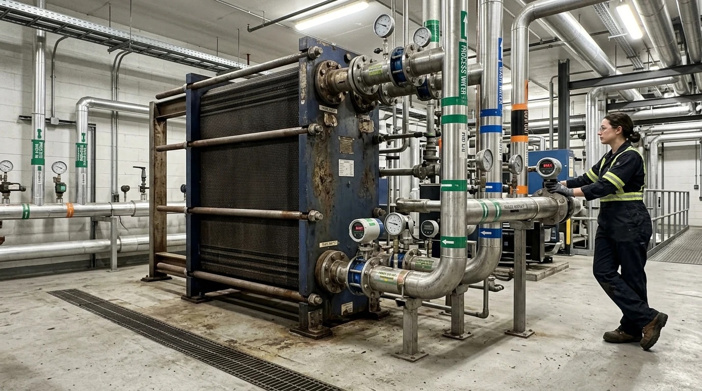
To cut operational costs safely and establish a clear capital investment case, textile operators require a structured, data-driven approach to system design and integration. EnerTherm Engineering addresses this need through a specialised 7-step energy audit methodology tailored specifically for industrial dye houses and finishing mills.
Step-by-Step Thermal Engineering Assessments
The energy audit process begins with a systematic evaluation of the facility's existing thermal infrastructure and water balance:
- Initial Consultation and Baseline Establishment: Establishing the plant's historical energy and water consumption profiles, production volumes, and utility billing records to set a clear baseline.
- On-Site Assessment Using Portable Instrumentation: Conducting physical measurements across the dye house. Engineers deploy non-invasive portable instruments, including power analysers to measure pump electrical loads, ultrasonic leak detectors to locate steam trap losses, and high-resolution thermal imaging cameras to map convective heat losses from uninsulated valves and pipework.
- Data Analysis Through Energy Modelling and Thermal Simulation: Importing the logged flow rates, discharge cycles, and temperature profiles into advanced thermodynamic simulation software. This stage models the complex, variable heat-discharge patterns and determines the optimal pinch points.
- Identification of Energy Conservation Measures (ECMs): Designing customised heat recovery configurations (such as the wide-gap plate heat exchanger and integrated storage setups) and calculating their expected savings.
- Detailed Audit Report Preparation: Compiling a comprehensive engineering report that details the proposed modifications, exact capital expenditure (Capex) requirements, annual operational cost savings (Opex), and calculated payback periods.
- Implementation and Commissioning Support: Managing the physical installation of the heat exchangers, piping, and automated control systems, ensuring integration is executed with minimal production downtime.
- Ongoing Measurement and Verification (M&V): Tracking and verifying actual post-implementation energy savings over months of operation to prove performance and validate the return on investment.
Portable Instrumentation and Thermal Simulation
The accuracy of the thermodynamic model depends directly on the quality of the field data collected during the on-site assessment. Standard plant meters are often insufficient for capturing rapid, transient temperature spikes and flow surges during vat discharges.
By utilising temporary clamp-on ultrasonic flow meters, engineers can log the exact volumetric discharge rates of individual dye vats without interrupting production. Combining this data with high-speed temperature loggers reveals the precise heat-rejection curves. These logged values are then run through thermal simulation software to model the performance of the wide-gap heat exchanger, preventing over-specification and ensuring the system is perfectly sized for the plant's actual operating profile.
Measuring and Verifying Energy Savings Using IPMVP
Baseline Modelling and Post-Implementation Reporting
To secure capital approval and comply with corporate sustainability mandates, energy savings must be quantified with high scientific rigour. Industry professionals widely utilise the International Performance Measurement and Verification Protocol (IPMVP) as the global standard for this process. Under the IPMVP framework, energy savings cannot be directly measured because they represent the absence of energy use. Instead, savings are calculated by comparing measured energy use after implementation against a mathematically adjusted baseline:
Energy Savings=(Baseline Energy Use±Adjustments)−Reporting Period Energy UseThe baseline model is established during the initial energy audit, correlating fuel and electricity consumption with key independent variables such as production volumes (kilograms of dyed fabric), ambient outdoor temperatures, and specific dye recipes. Post-implementation, meters continuously track the actual steam and fuel consumption of the boilers. The baseline model is then adjusted to reflect the actual production throughput during the reporting period, ensuring a fair, statistically valid comparison. This IPMVP-adherent reporting provides transparent, third-party verifiable proof of energy cost reductions to corporate boards and financial institutions.
Aligning with OEKO-TEX, ZDHC, and the Higg Index
Implementing advanced effluent heat recovery does more than just cut operational costs; it aligns the facility with major international environmental standards. Brands and retail buyers increasingly evaluate supply chain partners based on standardised sustainability scores. Key frameworks include:
- The Cascale Higg Index: The Higg Facility Environmental Module (Higg FEM) evaluates energy use, water consumption, and greenhouse gas emissions. Integrating this heat recovery system dramatically improves the plant's Higg FEM energy efficiency score, making the facility a preferred supplier for global apparel brands.
- Zero Discharge of Hazardous Chemicals (ZDHC): The ZDHC Resource Efficiency Module (REM) highlights water and energy conservation as key pillars of sustainable chemistry and wet processing. Efficient heat recovery lowers the temperature of the effluent before it reaches the ETP, protecting the biological treatment processes that remove hazardous chemical residues.
- OEKO-TEX: Standard certifications require manufacturers to optimise resource efficiency and minimise environmental impacts, which are directly addressed by capturing waste heat and lowering total fuel consumption.
- Regulatory Frameworks: In the UK and EU, large enterprises must comply with the Energy Savings Opportunity Scheme (ESOS) and the recast EU Energy Efficiency Directive (EU) 2023/1791. Implementing waste heat recovery provides a highly effective, rapid-payback measure to fulfil these mandatory audit requirements.
Rapid Payback and Long-Term Value
With heating cost reductions of up to 63.2% and a dramatic reduction in boiler load, the financial return on effluent heat recovery systems is exceptionally strong. Typical capital payback periods are under 1.8 years. For dye houses processing large daily volumes of fabric, the operational cost savings translate directly to increased profitability, insulating the business against energy price volatility and positioning the facility as a leader in sustainable textile manufacturing.
This article reflects the independent analysis and editorial opinion of EnerTherm Engineering. Product names, trademarks, and brands mentioned belong to their respective owners. EnerTherm Engineering is not affiliated with, endorsed by, or a licensee of any third-party software or product mentioned unless explicitly stated.

Managing Director — EnerTherm Engineering
Dr. François Pierrel is Managing Director of EnerTherm Engineering with over two decades of expertise in thermal design, heat transfer, and industrial energy optimisation. He holds a PhD in Heat Transfer from Cranfield University and a Post-Doctorate from Heriot-Watt University.
