Why Dye House Heat Recovery Systems Cut Boiler Fuel
How 60-80°C dye-house effluent preheats incoming water through a plate heat exchanger.
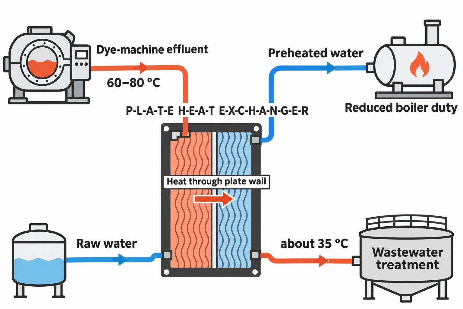
Dye house heat recovery systems transfer heat from hot dyeing effluent and rinse water into incoming process water before the boiler supplies further heat. In a typical wet-processing arrangement, dye-machine effluent leaves at 60 to 80°C, while incoming raw water may enter near ambient temperature. A plate heat exchanger can capture part of that temperature difference, preheating clean water and reducing the steam or hot-water duty needed for the next batch.
For a dye house manager, this is a direct boiler-fuel issue. Each hot drain carries energy that the site purchased moments earlier. If it passes untreated through the drain system, the boiler must heat a fresh volume of cold water for the next dyeing, washing or rinsing operation.
The opportunity is strongest where batch dyeing produces repeated hot discharges and regular demand for lower-temperature process water. The engineering task is to match those streams in time, protect the heat exchanger from textile residues and preserve production continuity.
Where dye houses lose boiler heat
Hot drainage creates two thermal duties
Dyeing machines fill, heat, hold, drain and rinse in a repeating cycle. Jet, overflow, package and winch machines may discharge hot liquor over a short period, followed by intervals with little or no flow. The wastewater then requires cooling before treatment, while incoming water requires heating before reuse in production.
Without heat recovery, the boiler provides the full temperature rise for clean make-up water. The effluent system receives the unwanted heat. This increases boiler fuel use and can add cooling or dilution demand downstream.
A heat-recovery system links these duties. Hot effluent flows through one side of a heat exchanger and incoming clean water through the other. The streams remain physically separate, but heat passes through the exchanger wall into the clean-water circuit.
The ENERGY STAR textile-industry guide illustrates a dye-house arrangement in which effluent at 60 to 80°C preheats raw water through a plate heat exchanger before wastewater enters treatment at about 35°C. Individual mills will produce different temperatures and flows, but the principle is consistent: less temperature lift at the boiler means less fuel for process hot water.
The value lies in the next useful demand
Recovered heat cuts boiler fuel only when a process can use it. A tank of warm water with no destination creates little benefit and can become a source of standing loss.
Suitable heat sinks in dye-house effluent and hot-water recovery projects include:
- Dye-machine make-up water
- Rinse-water preparation
- Washing and scouring water
- Central process hot-water tanks
- Cleaning water where temperature and water-quality requirements permit
The strongest match is usually a frequent water demand that can accept moderate-temperature water directly. If recovered water needs substantial steam trimming before use, the project may still save fuel, but less than a well-matched low-temperature duty.
Effluent cooling becomes productive work
Wastewater treatment often benefits from a controlled reduction in incoming temperature. A properly integrated recovery system therefore provides useful cooling and heating at the same time.
Not every hot drain should feed a heat exchanger. Some streams contain chemicals, fibres or dye residues that make direct exchange impractical. Others occur outside the operating window of potential heat sinks. The audit must identify streams with recoverable heat and a workable destination.
Identify where your plant is losing energy and quantify the savings potential — our audits map every heat source, sink, and waste stream in your facility.
How dye house heat recovery systems operate
Plate heat exchangers transfer heat without mixing water
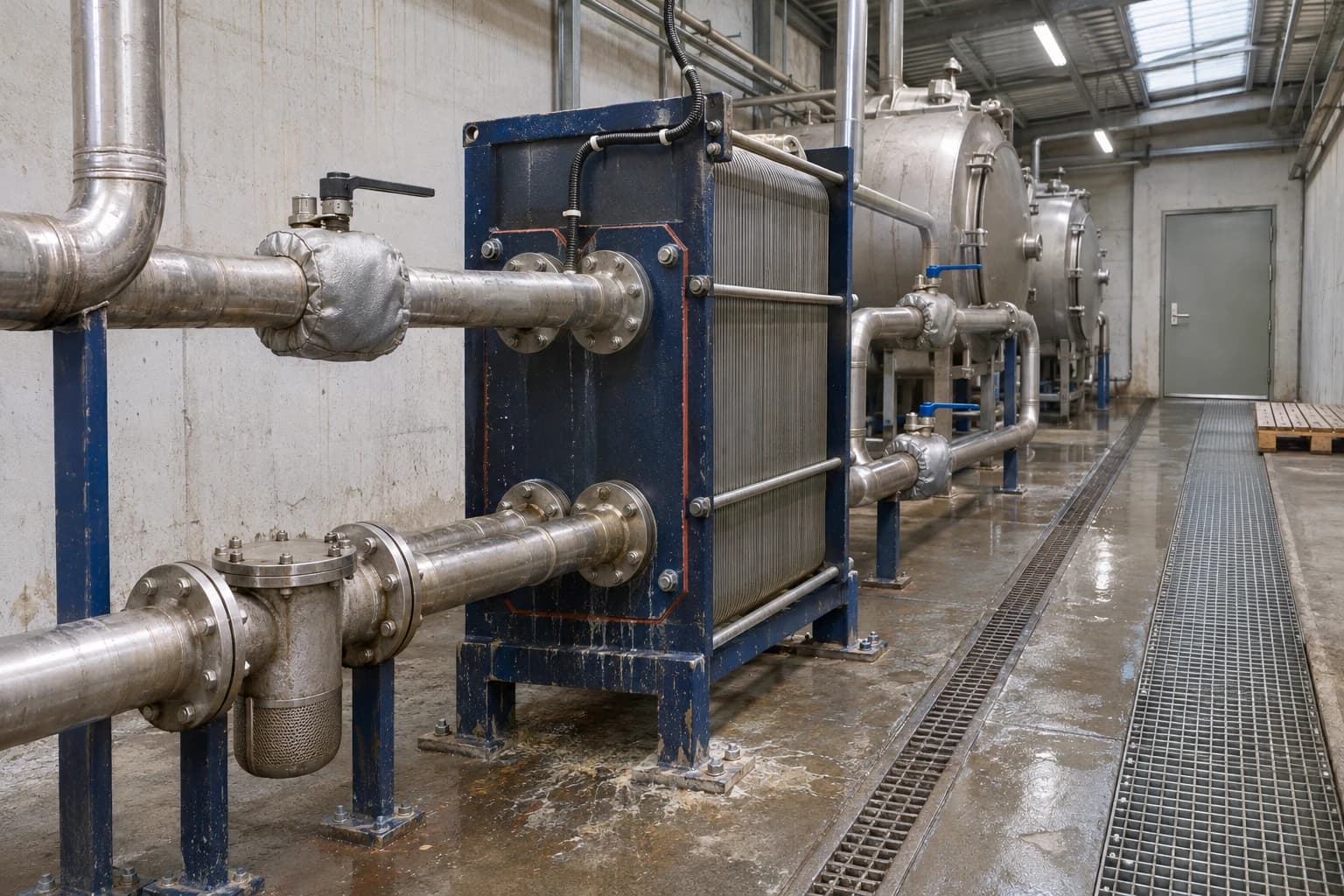
Plate heat exchangers are widely used for dye-house heat recovery because corrugated plates provide high heat-transfer area in a compact heat exchanger. Turbulent flow improves heat transfer and can support close temperature approaches between hot effluent and cold incoming water.
The separate circuits protect fresh process water from wastewater contamination. The system must maintain pressure relationships, gasket integrity and isolation arrangements that prevent cross-contamination during normal operation and maintenance.
A typical arrangement includes an effluent collection route, solids protection where required, a plate heat exchanger, clean-water pipework and a hot-water buffer tank. Control valves direct flow according to tank temperature, available effluent heat and demand for preheated water.
Fouling determines long-term output
Textile effluent is difficult service for a heat exchanger. Dye residues, lint, fibres, salts, alkalis, surfactants and finishing chemicals can deposit on heat-transfer surfaces. The risk changes with fibre type, dye class, recipe, chemical dosing and cleaning practice.
A design should start with representative effluent sampling and a review of batch recipes. It should then establish whether the heat exchanger needs screens, filtration, settlement control or another form of pre-treatment.
Practical features commonly include:
- Isolation valves and a bypass route
- Pressure and temperature measurement points across the heat exchanger
- Drainage points for safe maintenance
- Sufficient access for inspection and cleaning
- Compatible plate, gasket and seal materials
- Controls that protect dye-machine drainage from excessive back-pressure
A rising pressure drop across the heat exchanger can indicate fouling. A falling clean-water outlet temperature can show declining heat-transfer performance. Monitoring both conditions allows the maintenance team to plan cleaning before recovery performance and production reliability suffer.
Buffer tanks resolve timing mismatches
A buffer tank often decides whether a recovery scheme produces annual savings or performs well only during a brief test. It stores preheated water when a hot discharge occurs and releases it when the next process demand arrives.
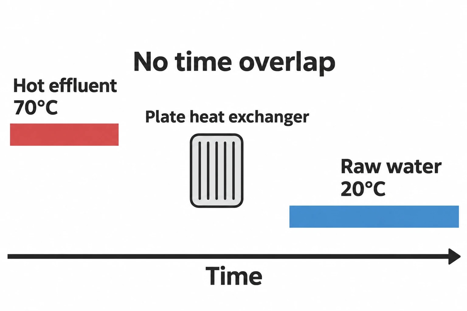
Without storage, a recovery system depends on simultaneous hot-effluent flow and cold-water demand. Batch production rarely provides that coincidence consistently. One machine may drain at 80°C while another does not begin filling for an hour.
Tank size should be based on measured operating data, including:
- Batch discharge volume and temperature
- Incoming-water temperature
- Drain timing and duration
- Clean-water demand by machine and recipe
- Required process-water temperature
- Available space and insulation performance
- Permitted water-storage conditions
Oversizing a tank can add capital cost and standing losses. Undersizing it can force hot effluent to bypass recovery during peak discharges. The correct volume follows from the batch schedule, not a generic sizing rule.
Heat pumps can raise lower-grade recovered heat
Direct heat exchange should be assessed first because it transfers heat without an additional electrical load. A heat pump may be appropriate where effluent remains warmer than the available clean-water demand can accept, or where a process needs water hotter than direct exchange can provide.
The 2022 Applied Thermal Engineering study, “Optimising wastewater heat recovery systems in textile dyeing processes using pinch analysis”, modelled a heat-exchanger and heat-pump network for textile dyeing. Its cost-optimal case reduced energy use by 28.64% and reported a 4.32-year payback.
Those figures are results from a modelled process, not a savings promise for individual UK mills. Their value lies in the approach: the researchers defined feasible operating scenarios before using pinch analysis to configure the network. Heat pumps require the same discipline on site. Source temperature, required delivery temperature, operating hours, electrical consumption and maintenance access determine whether the additional equipment improves the business case.
Why batch timing governs viable heat recovery
Daily averages can mislead a capital decision
A survey may show wastewater at 70°C and raw water at 20°C. That indicates a possible opportunity, but it does not establish annual boiler savings.
Dye houses operate around recipes, machine availability, fibre types, colour changes, dwell periods and rinse sequences. Hot wastewater may arrive in short peaks. Water demand may occur later, at a different flow rate or at a temperature that limits the heat the process can accept.
A useful audit records each relevant stream by machine, batch and time rather than relying on daily utility totals.
| Stream record | Reason for collecting it |
|---|---|
| Batch volume or flow rate | Quantifies potential recovered heat |
| Inlet and outlet temperatures | Establishes the usable temperature range |
| Start time and duration | Tests whether source and sink coincide |
| Machine, recipe and fibre type | Shows variation across production |
| Solids and chemical content | Informs heat-exchanger design and materials |
| Required clean-water temperature | Identifies practical heat sinks |
This identifies whether a central recovery system, machine-group system or buffer tank offers the most useful fit.
Pinch analysis establishes the recovery target
Pinch analysis compares site hot streams with cold streams to identify the minimum practical heating and cooling demands after heat integration. In a dye house, it prevents engineers from assessing one drain line in isolation while missing interactions among dye machines, rinses, hot-water storage and effluent treatment.
The method also helps match heat quality to the right process duty. High-temperature heat should not be allocated to a duty that could accept lower-grade recovered water if that leaves another clean-water demand dependent on steam. Correct matching preserves more available heat for boiler displacement.
For batch operations, the analysis needs time-based scenarios. A network that appears attractive from averaged flow data can underperform if its hot and cold streams do not overlap in production. The Applied Thermal Engineering study identified this directly: textile dyeing combines processes with different operating times, temperatures and water use.

Identify where your plant is losing energy and quantify the savings potential — our audits map every heat source, sink, and waste stream in your facility.
Safety and production continuity in UK dye houses
The recovery system must not control the dye machine
Production equipment must continue to drain safely if the heat exchanger is fouled, isolated or under maintenance. A recovery system should not leave a dye machine waiting for tank capacity or create drain back-pressure that affects the process.
A normally available bypass route allows wastewater to follow the established effluent path during cleaning, fault response or maintenance. This temporarily reduces recovered heat but protects output and keeps the operating arrangement understandable for plant personnel.
Design reviews should also consider hot surfaces, flash steam, chemical exposure, drainage, valve access and safe isolation of the clean-water and effluent circuits.
Pressure-system changes require competent review
The Health and Safety Executive states that dye vessels containing steam or hot water above 0.5 bar(g), typically at temperatures above 110°C, are subject to the Pressure Systems Safety Regulations 2000. HSE guidance also highlights risks from stored energy, hot liquor and steam in high-temperature dyeing equipment.
Heat-recovery projects can change pipework, valves, protective devices and operating conditions around qualifying systems. A competent person should review relevant changes before installation. HSE requires a written scheme of examination and examination before use for qualifying pressure equipment.
For machinery safety, BS EN ISO 11111-7:2005+A1:2009+A2:2016 addresses dyeing and finishing machinery safety requirements alongside BS EN ISO 11111-1:2016. Recovery equipment should preserve safe access, guarding, isolation and the intended function of machine interlocks.
How an energy audit develops the project
Build a credible boiler-fuel baseline
A heat-recovery project needs more than a promising temperature reading. The baseline should distinguish process-heating fuel from changes caused by production volume, product mix, weather-related space heating and boiler operating conditions.
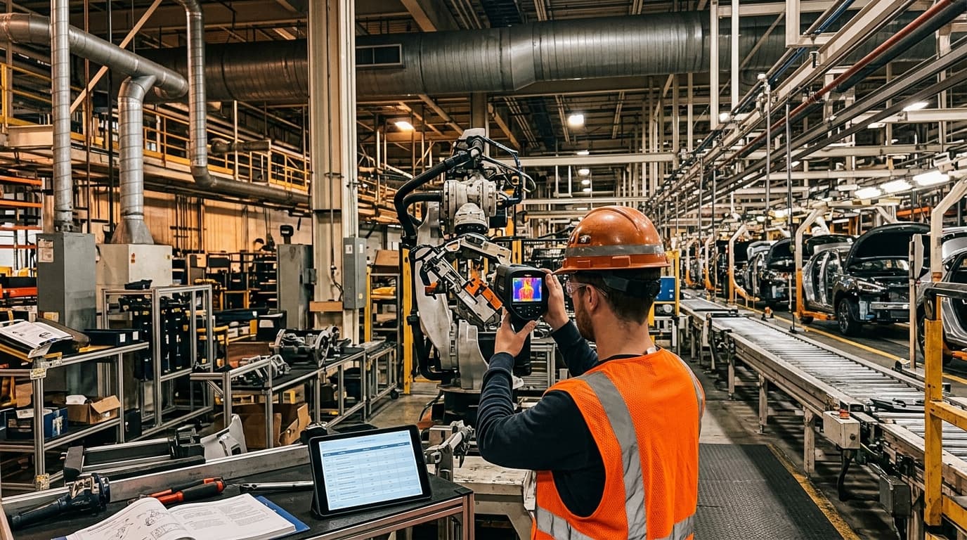
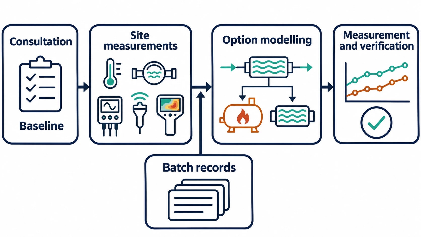
EnerTherm Engineering’s textile energy-audit process begins with consultation and baseline establishment. On-site work uses portable instrumentation, including temperature and flow measurements, power analysers, ultrasonic leak detection and thermal imaging. The objective is to link utilities data with batch-production records.
For dye-house heat recovery, priority measurements include boiler fuel, steam demand, hot-water flow, effluent temperature and volume, raw-water temperature, tank temperatures and bypass hours. Thermal imaging can also identify heat losses from hot-water tanks, valves and pipework that would undermine recovered-heat value.
Compare practical recovery options
The audit should model more than one arrangement before selecting equipment. Relevant scenarios include direct effluent-to-make-up-water exchange, central recovery to a hot-water tank, machine-group recovery and heat-pump assistance.
Each option should be assessed against:
- Annual recovered heat and expected boiler-fuel displacement.
- Batch timing and required buffer storage.
- Water quality, fouling risk and cleanability.
- Effects on effluent temperature and treatment operation.
- Capital cost, maintenance demand and planned downtime.
- Control philosophy, bypass operation and safe failure position.
- Measurement and verification after commissioning.
The ENERGY STAR guide cites wastewater heat-recovery paybacks of 0.3 to 4.2 years for wet-processing plants. That is a broad reference range. Fuel price, operating hours, boiler efficiency, usable temperature difference, production scheduling and maintenance access can move a project substantially within or beyond it.
Verify performance after commissioning
Measurement and verification should track normalised boiler fuel use alongside recovery-system operation. Core indicators include effluent inlet and outlet temperatures, clean-water inlet and outlet temperatures, recovery flow, tank temperature, heat-exchanger pressure drop and bypass hours.
These measurements reveal whether a drop in boiler fuel arises from the installed system or a temporary change in production. They also expose deterioration caused by fouling, altered recipes or changed machine scheduling.
ISO 50001:2018 provides a framework for improving energy performance through measured baselines and continuing review. For a dye house, this means treating recovered heat as a monitored utility contribution rather than assuming the commissioned design will retain its original performance indefinitely.
Dye house heat recovery is a boiler-fuel measure
This article reflects the independent analysis and editorial opinion of EnerTherm Engineering. Product names, trademarks, and brands mentioned belong to their respective owners. EnerTherm Engineering is not affiliated with, endorsed by, or a licensee of any third-party software or product mentioned unless explicitly stated.

Managing Director — EnerTherm Engineering
Dr. François Pierrel is Managing Director of EnerTherm Engineering with over two decades of expertise in thermal design, heat transfer, and industrial energy optimisation. He holds a PhD in Heat Transfer from Cranfield University and a Post-Doctorate from Heriot-Watt University.
