UK Textile Energy Audits: The Cost of Stenter Heat Loss
A stenter trial identified 884 kW of recoverable exhaust energy and up to 21% savings.
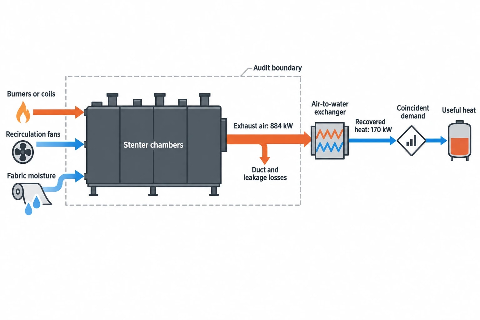
A peer-reviewed 2022 field-trial study recorded 884 kW of energy in the exhaust-air stream of one stenter machine, with its energy-flow diagram identifying 170 kW of potential recovery for water heating. The study examined a specific machine under field-trial conditions, so its figures cannot be transferred directly to a UK finishing plant. They do, however, show the scale of heat that can leave a stenter stack after the site has already paid to generate it.
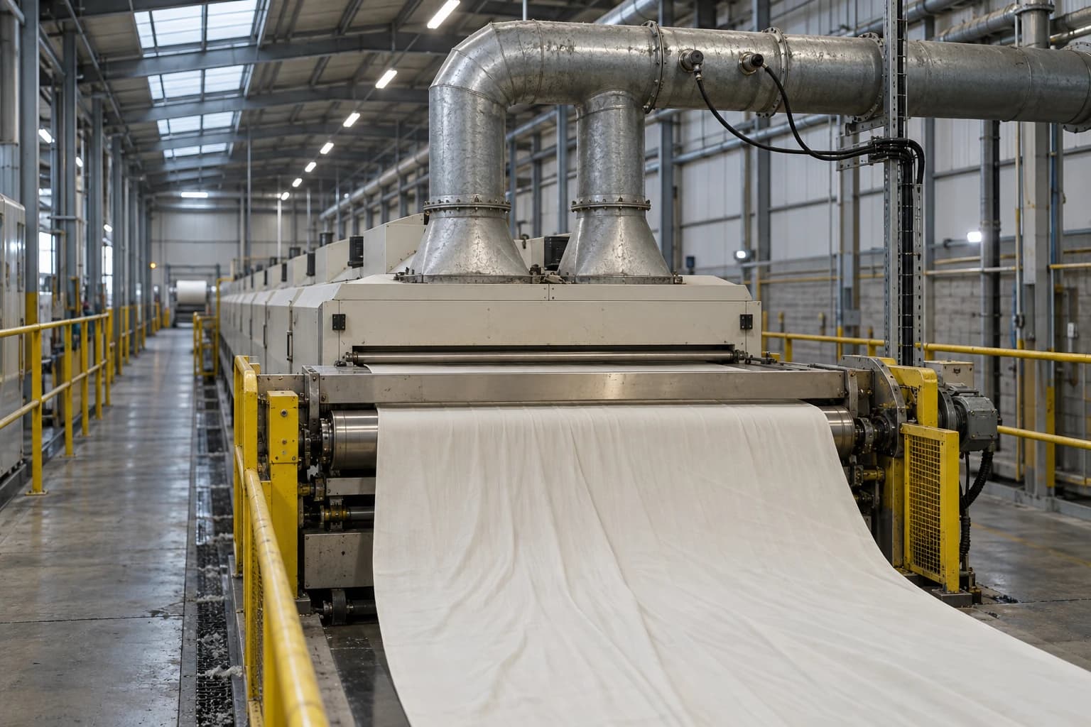
For UK dyeing, coating and finishing operations, stenter heat loss deserves detailed audit attention. Gas, thermal oil or steam supplies the heat. Fans move large volumes of process air. Exhaust removes evaporated moisture and process contaminants. Fresh air then enters the machine and requires reheating. The losses sit at the meeting point of fuel cost, electrical demand, fabric quality and emissions compliance.
An industrial energy audit for a UK textile plant should examine the stenter as a production system, not an isolated gas consumer. The practical question is whether the site can reduce avoidable exhaust heat loss, recover useful heat and preserve the operating conditions required for saleable fabric.
What the 884 kW stenter study did, and did not, establish
A measured case study, not a universal benchmark
The 2022 paper, “Investigations on energy assessment, conservation potential, and recovery opportunities for stenter machines based on the field trial”, examined an industrial stenter using field-trial data. Its authors reported 884 kW of energy in the machine’s exhaust air within the study boundary.
The paper identified several potential improvements for that machine:
- Optimised operating conditions reduced actual energy consumption to 730 kW, a reported 10% reduction.
- Preheating inlet air using exhaust energy reduced energy requirement by 7%.
- Recovering heat for water heating offered 170 kW of recovery potential, described as 21% saving potential.
- Appropriate operating conditions could save 15% to 20% of stenter energy while maintaining fabric quality.
Those results make a strong case for measurement. They do not provide a design duty for another site. A UK plant may run different fabric weights, finishes, chamber temperatures, production speeds, moisture loads and exhaust settings. Its available hot-water demand may also differ sharply from the trial conditions.
The measurement boundary matters
“Recoverable heat” can mean several things. A hot exhaust stream may contain substantial energy, but a project creates a financial saving only where a heat exchanger can transfer that energy to a useful demand at the right time and temperature.
The relevant audit boundary should identify:
- heat entering the stenter through burners, steam coils or thermal-oil coils;
- electricity used by recirculation and exhaust fans;
- air entering and leaving the machine;
- fabric moisture entering and leaving the chambers;
- recoverable heat available in the exhaust;
- heat demand that can accept recovered energy;
- losses from ducts, access doors, insulation and uncontrolled leakage.
This prevents a preliminary heat-recovery figure becoming an overstated savings forecast.

Identify where your plant is losing energy and quantify the savings potential — our audits map every heat source, sink, and waste stream in your facility.
Why stenter exhaust drives fuel and electricity costs
Exhaust removes sensible and latent heat
Stenter exhaust carries sensible heat in hot air and latent heat from water evaporated from the fabric. The machine needs extraction to remove moisture and maintain drying conditions. It may also need to remove lint, oils, finishing residues or volatile compounds generated by the process.
Each additional volume of extracted air has two energy effects. The exhaust fan consumes electricity to move it through chambers, ducts and the stack. Replacement air enters the stenter and requires heating to process conditions. A change in extraction rate can therefore alter fuel consumption and fan demand.
The thermal impact can remain hidden where operators focus on chamber temperature alone. Two stenters can operate at the same temperature setpoint while using different quantities of fuel because one has higher uncontrolled infiltration, a greater exhaust rate or weaker recirculation.
Product mix changes the baseline
A stenter does not process a uniform load. Fabric width, weight, construction, coating, incoming moisture, finish chemistry and line speed all affect drying duty. A heavy coated textile with high wet pickup cannot be compared fairly with a lightweight fabric using one site-wide kWh-per-metre figure.
Useful energy-intensity indicators include:
| Indicator | Appropriate use | Limitation to manage |
|---|---|---|
| Gas per tonne of finished fabric | Stable product families and weight-based production | Product weight and moisture variation can distort results |
| Energy per kilogram of evaporated water | Drying-focused assessment | Requires reliable fabric-moisture data |
| Total stenter energy per production hour | Monitoring steady campaigns | Does not account for loading differences |
| Energy per metre for a defined recipe | Repeated fabric and finish runs | Unsuitable for mixed product ranges |
ISO 50006:2023 provides guidance on energy performance indicators and energy baselines. For stenters, that means defining the activity variables that drive energy use and separating materially different product groups. The energy baseline should reflect actual production, not a convenient average that hides inefficient runs.
What a UK textile energy audit should measure
Establish a representative operating period
A stenter audit needs more than one stack-temperature reading. The assessment should cover enough production to capture relevant fabric families, normal recipe changes, shifts and operating conditions. A period with an unusual order mix, incomplete maintenance or a temporary bypass arrangement can produce misleading conclusions.
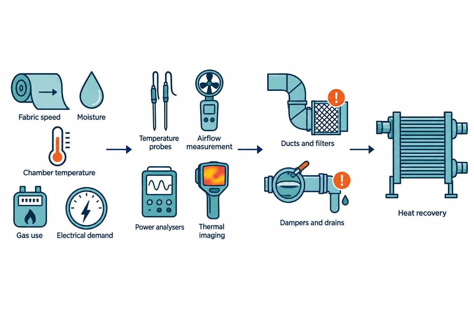
The audit record should connect process data with utility data. It should capture fabric speed, width, mass, incoming and outgoing moisture where available, chamber temperatures, recirculation settings, exhaust settings, burner or coil operation, gas use and electrical demand.
Portable instrumentation can support this work. Temperature probes, airflow measurement, power analysers and thermal imaging provide different parts of the evidence. Thermal imaging can reveal failed insulation, hot surfaces and leakage around doors or ductwork. Power analysers can distinguish fan demand from wider machine consumption. Airflow and exhaust measurements establish the potential heat source for recovery.
Record the condition of the exhaust stream
Stenter exhaust is rarely clean, dry air. Lint, oil, finish residues and condensable compounds can foul heat-transfer surfaces. The audit should inspect ducts, filters, dampers, drains and accessible exchanger surfaces before specifying equipment.
Questions that affect a recovery scheme include:
- Is exhaust flow stable across the product programme?
- Does the exhaust contain residues likely to foul a heat exchanger?
- Is there evidence of condensation, corrosion or blocked drainage?
- Does the system allow cleaning and inspection?
- Would an added exchanger increase pressure drop enough to raise fan power?
- Does the process require bypass operation during cleaning or maintenance?
These findings distinguish a technically possible recovery opportunity from an asset that will be difficult to keep operating.
Heat recovery options for stenter exhaust
Air-to-air inlet preheating
Air-to-air heat recovery transfers energy from exhaust air to fresh make-up air before it enters the stenter. The recovered heat reduces the duty required to bring incoming air towards process temperature.
This option can suit sites with consistent fresh-air demand and a layout that allows ductwork modification. It requires assessment of pressure drop, contamination risk, cleanability and controls. A fouled exchanger can reduce heat transfer and increase fan energy. A bypass may be required to protect production during cleaning or abnormal operating conditions.
The field-trial study reported a 7% energy-requirement reduction from inlet-air preheating. A UK audit should calculate its own result from measured flow, temperature, operating hours and actual fuel displacement.
Air-to-water heat recovery
Air-to-water recovery transfers exhaust heat into a water circuit. Relevant textile uses can include dye-house make-up water, washing, cleaning or other low-temperature hot-water duties. The financial case depends on coincidence: the stenter must generate heat while another process needs it.
A site may have substantial annual hot-water consumption but limited demand during the same production hours as the stenter. Storage may improve utilisation, although it adds capital cost, space requirements, heat loss and controls. An audit should produce a time-based heat-source and heat-sink profile before a supplier sizes the heat exchanger.
Exhaust-rate and recirculation control
Heat-recovery equipment cannot correct excessive extraction. Process teams should first establish the approved operating envelope for each fabric family and finish. This should define chamber temperatures, exhaust settings, recirculation limits, fabric speed and quality checks.
Recirculation retains heat inside the stenter, reducing the amount of fresh air requiring heat. Excessive recirculation can impair moisture removal, affect finishing conditions or create safety concerns. Operators need settings supported by trials and quality evidence, rather than a blanket instruction to reduce exhaust.
Variable-speed fan control may reduce electricity use where lower exhaust flow is acceptable. The audit must confirm that fan operating points, airflow proving and safety interlocks remain suitable after any change.

Identify where your plant is losing energy and quantify the savings potential — our audits map every heat source, sink, and waste stream in your facility.
Building a defensible cost-benefit case
Calculate usable heat, not stack heat
The cost-benefit model should start with measured heat available from the exhaust, then reduce it for practical constraints. These include heat-exchanger effectiveness, fouling allowance, pressure drop, fan and pump electricity, seasonal changes in incoming-air temperature, cleaning outages and the availability of a water or air heat sink.
A project appraisal should identify the fuel displaced. Recovered heat that replaces gas-fired hot-water production has a different value from heat that displaces steam generated by a boiler, or heat with no useful destination during some shifts.
Capital costs should include more than the exchanger package:
- Duct alterations, supports, access platforms, drainage and insulation.
- Fans, pumps, valves, controls and instrumentation.
- Integration with fresh-air ducts or hot-water circuits.
- Electrical and control-system modifications.
- Installation during planned maintenance shutdowns.
- Commissioning, performance testing and operator training.
- Cleaning access, inspection routines and replacement parts.
Rank actions by certainty and production impact
Early actions may include repairing duct leakage, restoring insulation, cleaning existing heat-transfer surfaces, checking damper operation and reviewing control settings against current recipes. These measures can improve thermal performance with limited disruption and provide a more reliable basis for later capital decisions.
Heat recovery requires a detailed feasibility assessment. The audit should state the expected savings range, the operating assumptions behind it, the expected maintenance requirement and the conditions that would weaken the business case. An air-to-water scheme, for example, may depend on a dye-house hot-water load that falls during certain product campaigns.
Production planning should shape the installation plan. Stenter availability has high value, and intrusive duct work can require a planned shutdown. The project team should define the outage requirement, temporary operating arrangements, commissioning tests and acceptance criteria before approving capital expenditure.
ESOS Phase 4 makes site evidence more important
The UK compliance position
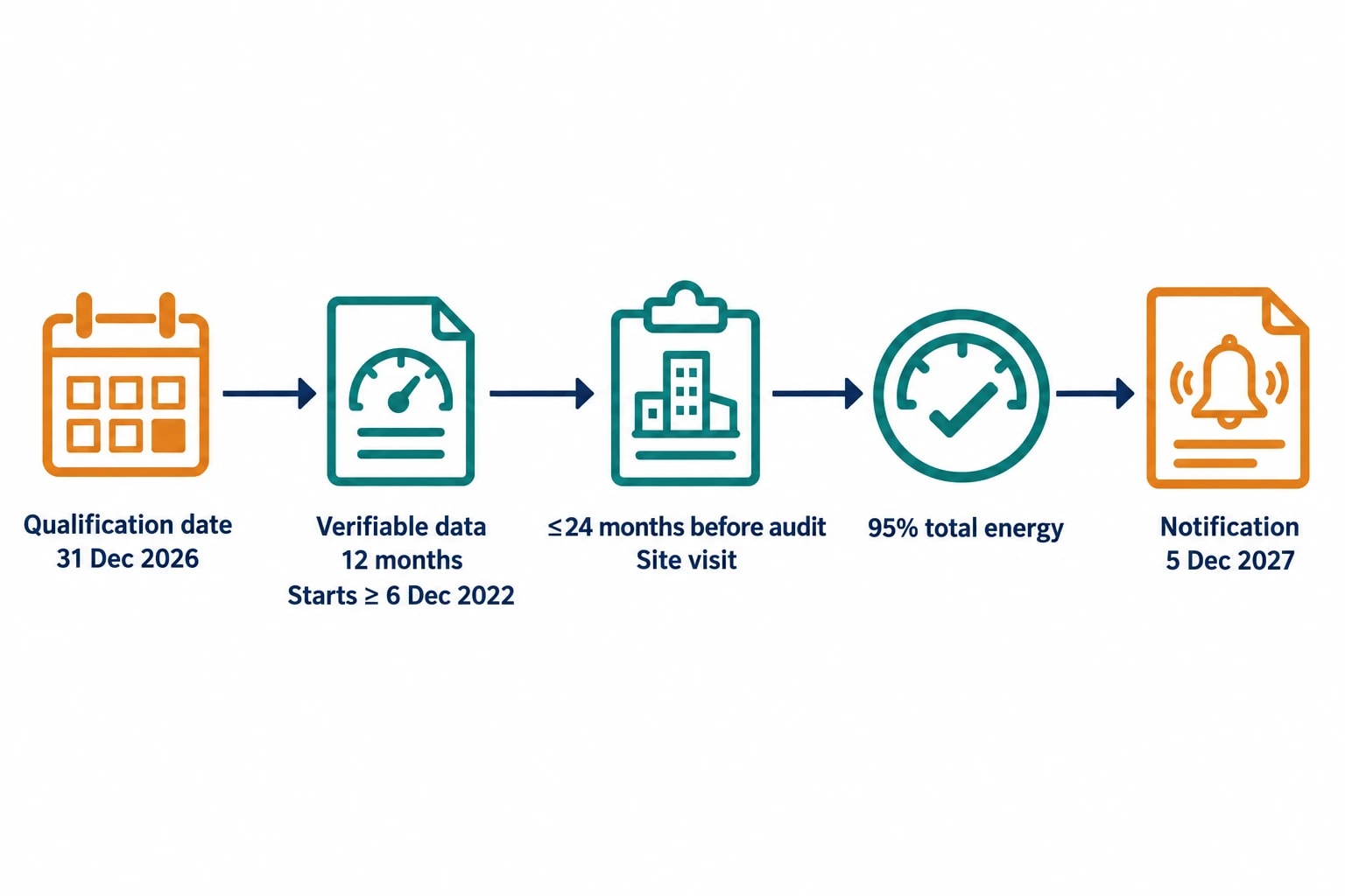
The Environment Agency states that ESOS Phase 4 applies to large UK undertakings on the qualification date of 31 December 2026. A large undertaking has 250 or more employees, or annual turnover above £44 million together with an annual balance-sheet total above £38 million.
The notification deadline is 5 December 2027. The governing framework is the Energy Savings Opportunity Scheme Regulations 2014, as amended.
For qualifying textile groups, significant energy consumption must account for at least 95% of total energy consumption. Buildings, transport, industrial processes and other energy uses form part of the calculation. A stenter may represent a major industrial-process load, but the audit evidence still needs to show how the full energy picture has been assessed.
Stenter data can support compliance and investment decisions
An ESOS-compliant audit must, so far as reasonably practicable, use verifiable energy-consumption data measured over a 12-month period. That period must begin no earlier than 6 December 2022 and no more than 24 months before the audit starts. Site visits are required.
Phase 4 also requires energy-intensity ratios for buildings, transport, industrial processes and other energy uses. For a textile site, stenter energy intensity should connect metered energy with an appropriate production activity indicator. Fabric category, mass and moisture load may need to sit alongside the headline ratio to explain movement over time.
The same evidence strengthens a capital request. Meter records, production reports, maintenance history and measured exhaust conditions allow finance and operations teams to test whether a predicted heat-recovery saving remains valid under real operating conditions.
Safety, emissions and quality define the operating limit
Energy changes require a safety review
The Health and Safety Executive identifies stenters as equipment requiring specific fire precautions. Its guidance states that the heat supply should cut off automatically if material stops in the stenter. It also advises against turning on gas burners until fans have run for ten minutes, as fibres can settle quickly.
Any change to exhaust, recirculation, burner control or heat-recovery ducting should be reviewed through the site’s machinery-safety arrangements. Airflow proving, burner interlocks, emergency stops, temperature limits, inspection routines and cleaning procedures remain part of the energy project.
Permits and fabric quality remain central
Textile and fabric coating and finishing activities may fall within the local-authority pollution prevention and control regime. Process Guidance Note PG6/8 covers textile and fabric coating, printing and finishing. Altering exhaust rates, ductwork, condensate collection or emission points can affect permit compliance and maintenance arrangements.
Fabric quality provides the final acceptance test. Trials should compare like-for-like production runs and assess width, shrinkage, handle, finish cure, shade and final moisture. The audit should identify heat that can be recovered, heat that needs to remain in the process and losses that can be removed without compromising the product.
This article reflects the independent analysis and editorial opinion of EnerTherm Engineering. Product names, trademarks, and brands mentioned belong to their respective owners. EnerTherm Engineering is not affiliated with, endorsed by, or a licensee of any third-party software or product mentioned unless explicitly stated.

Managing Director — EnerTherm Engineering
Dr. François Pierrel is Managing Director of EnerTherm Engineering with over two decades of expertise in thermal design, heat transfer, and industrial energy optimisation. He holds a PhD in Heat Transfer from Cranfield University and a Post-Doctorate from Heriot-Watt University.
