How Stenter Frame Exhaust Heat Recovery Cuts Gas Use
A 2024 study modelled combustion-air preheating at up to 60.8% below its base case
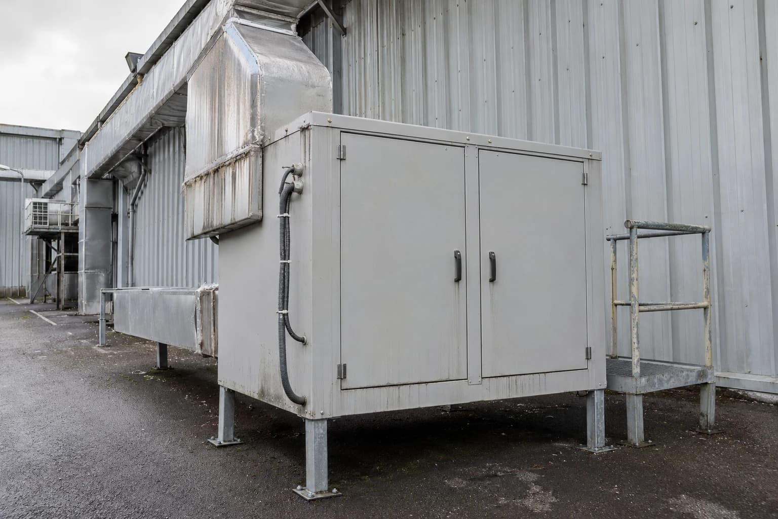
Stenter-frame exhaust heat recovery captures heat from hot dryer exhaust for reuse in combustion air, process water or incoming air, reducing the gas required to heat those streams. The EU Textiles Industry BREF identifies thermal treatment as a process with indicative yearly specific energy consumption of 0.5 to 4.4 MWh per tonne, a broad range reflecting fabric type, water removal, machine condition and operating practice.
For a UK dyeing or finishing plant, the stenter is often the most practical place to begin an energy audit. It combines a large gas demand with a continuous exhaust stream carrying sensible heat from hot air and latent heat associated with evaporated water. The recovery opportunity depends on conditions upstream of the heat exchanger. Excessive exhaust volume, damp fabric, dirty ducts and uncontrolled burner operation can leave a heat-recovery project recovering heat that should never have been supplied.
The strongest projects treat the stenter as one thermal system. Mechanical dewatering, air recirculation, exhaust-humidity control, burner maintenance, heat recovery and production scheduling must work together. This protects fabric quality while reducing gas use and unnecessary fan electricity.
Why Stenter Exhaust Is a High-Value Heat Source
Heated air and evaporation drive gas consumption
A stenter heats large volumes of circulating air while removing water from fabric and setting or curing the finish. Direct-fired machines use burner energy to maintain chamber temperature. The exhaust removes moisture, products of combustion and process emissions from the machine.
The energy loss is substantial because exhaust carries heated air and water vapour that required energy to evaporate. A heat exchanger can capture part of that energy before the gas leaves the stack. The usable result depends on exhaust temperature, volume flow, fouling rate, the available heat sink and the period for which heat supply and demand coincide.
Heat recovery does not replace correct drying control. It improves the energy balance once the machine has reached a stable, efficient operating condition.
Excess exhaust volume wastes both gas and electricity
The 2023 EU Textiles Industry BREF states that efficient stenter operation maintains exhaust humidity in the region of 0.1 to 0.15 kg water per kg of dry air. Lower humidity can indicate that too much air is being extracted. The stenter then heats air that performs little drying work, while exhaust fans consume additional electricity.
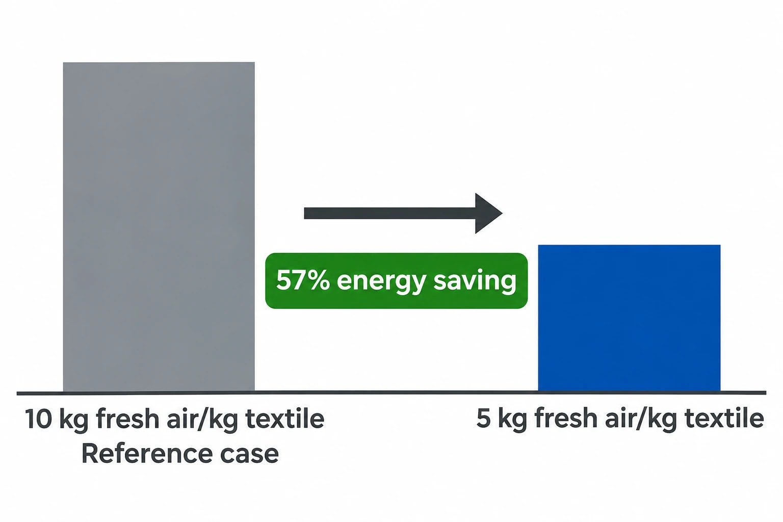
The BREF records that reducing fresh-air use from 10 kg to 5 kg per kg of textile produced delivered a 57% energy saving in the cited example. This is a reference case, not a forecast for an individual mill. Fabric construction, finish chemistry, required emissions control and machine design determine the achievable reduction on site.
An engineering team should establish whether the exhaust rate is driven by process need, emissions control, operator practice, poor sealing or a fixed-speed fan arrangement. The answer affects the correct size of the heat exchanger. Oversizing an exchanger around an inflated exhaust flow locks waste into the design.
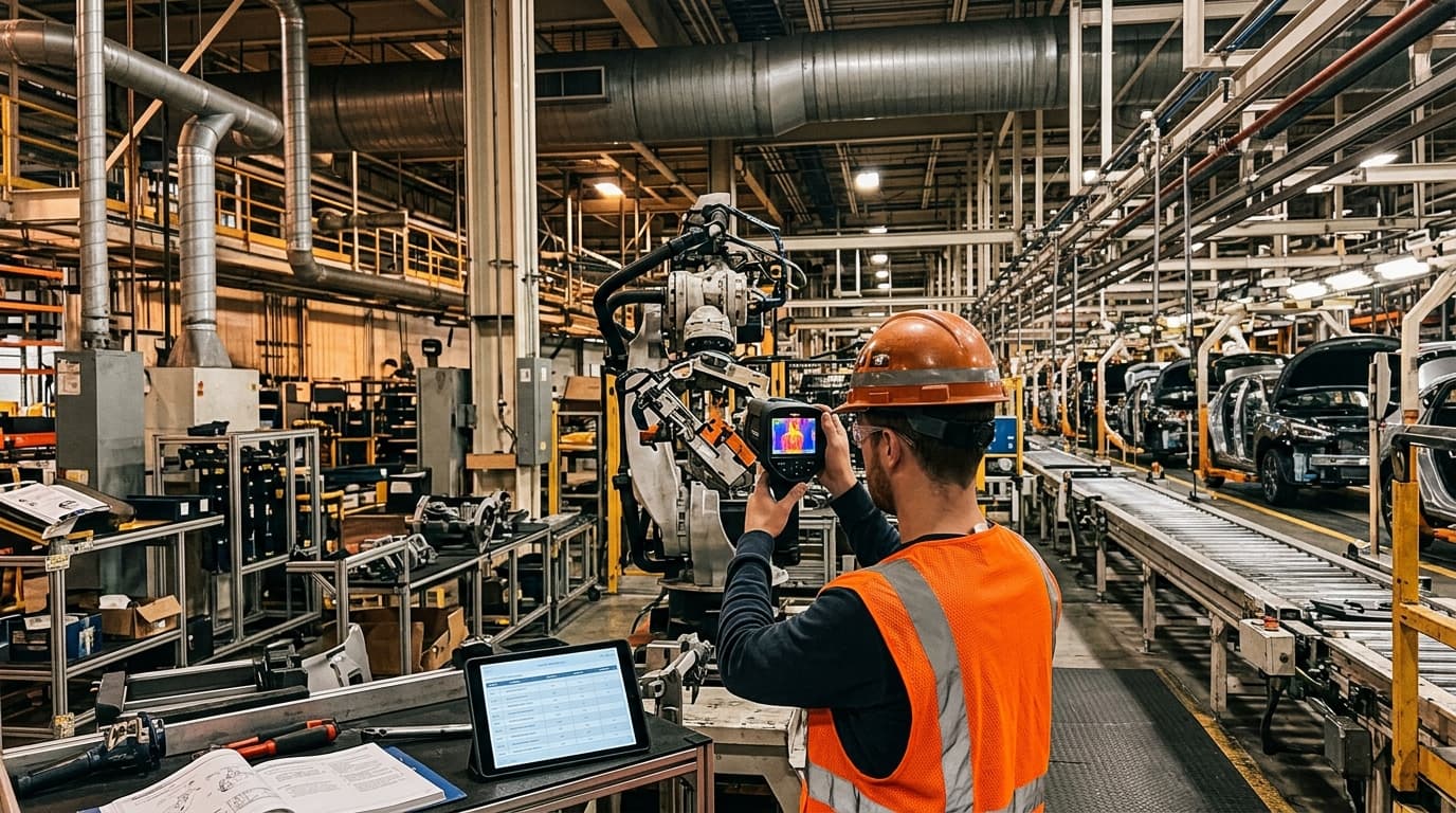
Identify where your plant is losing energy and quantify the savings potential — our audits map every heat source, sink, and waste stream in your facility.
How Stenter Frame Exhaust Heat Recovery Works
Combustion-air preheating reduces burner fuel demand
Combustion-air preheating transfers heat from exhaust gas to the fresh air supplied to a direct-fired burner. The burner then needs less gas to raise incoming combustion air to the required firing temperature.
This arrangement can be attractive because the heat source and heat user operate at the same time. It also avoids dependence on a separate hot-water demand elsewhere in the factory. The exchanger must suit burner-air requirements, pressure drop, safe temperature limits and fouling risk.
A 2024 study in Energy compared air preheating, hot-water generation and power generation from stenter exhaust. Its combustion-air preheating case reported a 60.8% reduction in energy consumption against its base case, driven by reduced fuel use, and the authors found it had the strongest economics of the three modelled options. That result is specific to the modelled system. It supports assessing combustion-air preheating, but is not a site-wide savings promise.
Hot-water recovery can serve the dye house
An air-to-water heat exchanger can transfer exhaust heat into a closed hot-water circuit. Potential uses include dyeing process water, wash-water preheating or other stable low-temperature hot-water loads.
This arrangement works best where the plant has a repeatable hot-water demand during stenter production. A storage vessel can manage short differences between exhaust availability and water demand, though storage introduces heat losses, capital cost and space requirements.
The EU BAT conclusions identify heat recovery from waste gases for warming process water or preheating combustion air. A project should compare both destinations rather than assume one configuration suits every finishing plant.
Air-to-air recovery can preheat incoming process air
Air-to-air recovery preheats fresh incoming air with stenter exhaust. It can reduce the burner duty associated with bringing ambient air to operating temperature. The design must retain adequate exhaust capacity, manage pressure drop and avoid transferring lint, condensate or contaminants to the supply side.
Indirect recovery equipment keeps exhaust and supply air separated by a heat-transfer surface. This separation is important where finishing recipes generate airborne contaminants. The final layout must also preserve access for cleaning and inspection.
| Recovery route | Useful when | Principal engineering checks |
|---|---|---|
| Combustion-air preheating | Direct-fired stenter runs steadily | Burner-air temperature limits, pressure drop, controls and safe integration |
| Process-water heating | Dye house or washing line has concurrent hot-water demand | Water temperature requirement, storage, corrosion protection and demand profile |
| Incoming-air preheating | Stenter requires significant fresh make-up air | Exhaust cleanliness, supply-air temperature, leakage and fan duty |
Stenter Frame Energy Saving Starts Before the Heat Exchanger
Reduce incoming fabric moisture
The cheapest kilogram of water to remove in a stenter is the kilogram removed mechanically beforehand. The BREF identifies centrifugal extraction, squeezing and vacuum extraction as applicable mechanical dewatering methods.
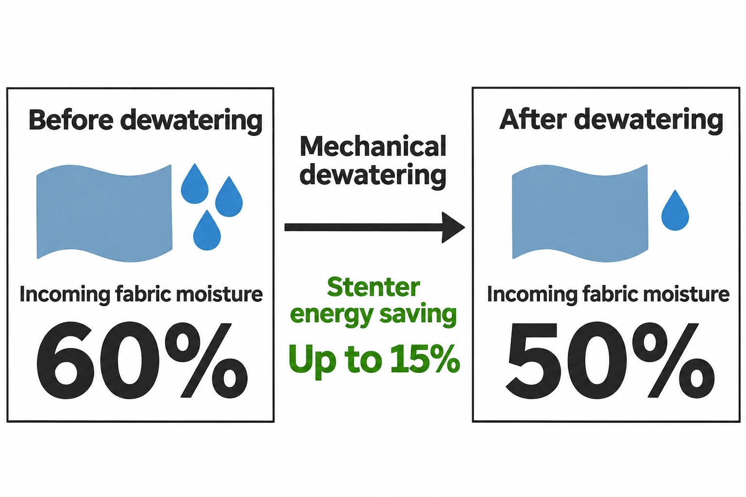
Its cited technical information reports that reducing incoming fabric moisture from 60% to 50% can save up to 15% of stenter energy, depending on substrate. The same source notes that vacuum extraction can perform better on synthetic fibres, while squeezing rollers can suit cotton fabrics. A plant should test the selected approach against fabric weight, construction, residual wet pick-up and downstream quality requirements.
Dewatering settings should form part of the stenter operating recipe. A stenter energy audit that records only gas consumption and output metres will miss changes in incoming moisture that explain shifts in fuel performance.
Control exhaust humidity and fabric residual moisture
Exhaust humidity, exhaust temperature, inlet-air condition, fabric temperature and outlet residual moisture form a useful set of operating indicators. Together, they show whether the machine is removing water efficiently or simply moving excessive hot air.
The BREF recommends adjusting exhaust airflow for drying efficiency and reducing it during idle periods. Dampers and variable-speed drives enable these changes, while humidity sensors and fabric-moisture measurement provide the basis for control.
The objective is stable product condition, not the highest possible exhaust humidity. A plant must retain enough extraction to manage process emissions and maintain safe, repeatable conditions. Operators should validate changes through width, shrinkage, handle, colour, cure and residual-moisture checks for the relevant fabric family.
Overdrying creates another avoidable loss. The BREF states that textile materials should not be dried below their natural moisture level. Cotton, wool, viscose and synthetic materials have materially different moisture behaviour, so one dryer recipe cannot serve every fabric quality safely.
Improve recirculation and burner condition
Stenter air recirculation reduces the amount of fresh air that burners must heat. The BREF identifies nozzle selection for fabric width, short nozzle-to-fabric distance and low internal pressure drop as measures for optimising air circulation. These measures are especially relevant during major upgrades or new-line specification.
Burner condition matters equally. The BREF calls for burner maintenance and control as a general energy-efficiency technique. Lint or oil can obstruct the burner-air inlet, while deposits and poor adjustment undermine combustion performance. A planned programme should include visual checks, filter attention, gas-train integrity checks, combustion measurement and specialist adjustment.
A heat-recovery project should begin after the mill has established that burners, dampers, sensors and recirculation fans perform as intended. Recovery equipment cannot correct poor combustion or uncontrolled airflow.

Identify where your plant is losing energy and quantify the savings potential — our audits map every heat source, sink, and waste stream in your facility.
Designing a Recoverable and Maintainable Exhaust System
Assess the real exhaust stream
A site survey should log representative production conditions rather than a single convenient operating point. Useful measurements include:
- Exhaust temperature, humidity and volume flow by chamber or exhaust branch.
- Gas use, burner firing pattern and production rate.
- Fan power, damper position and recirculation settings.
- Incoming and outlet fabric moisture.
- Fabric width, weight, fibre blend, finish chemistry and machine speed.
- Exhaust duct condition, leakage, lint accumulation and access constraints.
- Hot-water or combustion-air demand that can accept recovered heat.
This baseline distinguishes recoverable heat from theoretical heat. It also reveals whether one product family, shift or recipe creates a better initial case than the entire production schedule.
Design for lint, condensate and cleaning
Textile exhaust can contain lint, fibre fragments, oil aerosols and residues associated with finishing chemistry. As exhaust cools through a heat exchanger, water can condense. That condensate can carry contaminants and accelerate corrosion where material selection or drainage is poor.
The design review should cover upstream filtration or separation, exchanger geometry, drainage, access doors, wash-down method, condensate management and differential-pressure monitoring. High pressure drop raises fan electricity use and can offset part of the gas saving. Fouling reduces heat transfer, so a clean exchanger performs very differently from one left inaccessible behind ductwork.
The control system should bypass or limit recovery during unsuitable start-up, shutdown or low-load conditions. It should also prevent supply-air temperatures exceeding defined limits. These protections preserve stable drying and avoid creating a maintenance burden that operators bypass after commissioning.
Protect throughput and fabric quality
Production managers will judge a stenter energy-saving project by its effect on metres produced, rejects and repeatability. The commissioning plan should include agreed quality tests and a controlled sequence of operating changes.
A practical sequence is:
- Record a baseline across representative fabrics and production rates.
- Correct burner, damper, duct and sensor defects.
- Establish stable moisture and exhaust-humidity control.
- Commission recovery equipment with conservative setpoints.
- Compare gas, electricity, throughput and quality against matched production conditions.
- Adjust recipes and controls only after quality assurance confirms the result.
This process prevents a false saving created by underdrying fabric or reducing line speed. It also creates a defensible record for capital approval.
How an Energy Audit Builds the Investment Case
Measure gas use per useful production unit
A credible baseline usually reports gas and electricity against tonnes, kilograms or linear metres of finished fabric, while retaining the production variables that influence energy use. The chosen denominator should remain consistent across the measurement period.
The BREF uses MWh per tonne of textile materials processed as an energy-efficiency objective example. A mill may also need fabric-family baselines because a heavy cotton fabric with high wet pick-up cannot be compared directly with a lightweight polyester quality.
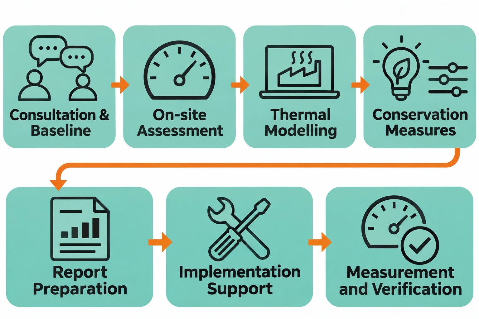
EnerTherm Engineering’s textile energy-audit approach can apply a seven-step structure: consultation and baseline establishment, on-site assessment using portable instrumentation, data analysis and thermal modelling, identification of conservation measures, report preparation, implementation support, and ongoing measurement and verification. For stenters, that method connects measured exhaust conditions to a defined heat user and a practical shutdown window.
Rank measures in the right order
Stenter upgrades compete for limited capital. Auditors should rank options by measured energy effect, production risk, maintenance requirement, emissions implications and installation practicality.
| Measure | Primary saving mechanism | Typical decision point |
|---|---|---|
| Mechanical dewatering | Less water evaporated in the stenter | Fabric-specific water removal and quality result |
| Exhaust humidity control | Lower hot-air discharge and fan demand | Sensor reliability and emissions requirement |
| Burner maintenance and tuning | Better combustion performance | Condition of burner, inlet filters and controls |
| Variable-speed exhaust control | Airflow matches drying load | Existing fan curve and safe operating range |
| Exhaust heat recovery | Reuse of otherwise discharged heat | Sufficient exhaust flow and concurrent heat demand |
| Improved insulation | Lower casing heat loss | Condition of enclosure and access for installation |
Measurement and verification should use a documented boundary, matched production data and a defined adjustment method for changes in fabric type, throughput and moisture. IPMVP protocols offer a recognised structure for this work. The final savings figure should reflect metered performance after commissioning, rather than a nameplate estimate.
UK Permitting and BAT Review for Textile Exhaust Projects
Include the recovery system in permit planning
In England and Wales, the Environmental Permitting (England and Wales) Regulations 2016 list textile pre-treatment or dyeing plants with a treatment capacity exceeding 10 tonnes per day under Schedule 1, Section 6.4 Part A(1)(a). The site’s permit conditions, emission controls and regulator engagement should therefore be reviewed before changing exhaust routing, stack conditions or treatment equipment.
An exhaust heat-recovery installation can alter gas temperature, condensate formation, pressure loss and the arrangement of existing exhaust-treatment equipment. Project teams should establish the permitted emission points, confirm required monitoring and define how the new system maintains access for inspection and maintenance.
Use EU textile BAT as an engineering reference
Commission Implementing Decision (EU) 2022/2508 sets the BAT conclusions for the textiles industry under the Industrial Emissions Directive. BAT 11 identifies recovery of heat from waste gases for process-water heating or combustion-air preheating. BAT 13 covers mechanical dewatering, prevention of overdrying, optimised stenter air circulation, monitored drying control and waste-gas heat recovery where sufficient flow exists.
For UK sites, these measures provide a detailed engineering reference for permit and BAT review alongside applicable domestic requirements. They reinforce a central operational point: heat recovery has greatest value when moisture control, exhaust flow and maintenance already support efficient drying.
This article reflects the independent analysis and editorial opinion of EnerTherm Engineering. Product names, trademarks, and brands mentioned belong to their respective owners. EnerTherm Engineering is not affiliated with, endorsed by, or a licensee of any third-party software or product mentioned unless explicitly stated.

Managing Director — EnerTherm Engineering
Dr. François Pierrel is Managing Director of EnerTherm Engineering with over two decades of expertise in thermal design, heat transfer, and industrial energy optimisation. He holds a PhD in Heat Transfer from Cranfield University and a Post-Doctorate from Heriot-Watt University.
