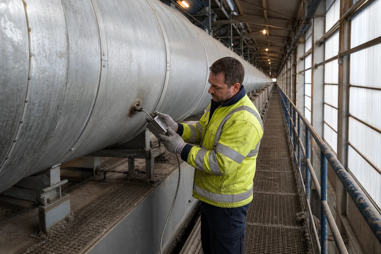
Why Textile Mills Are Auditing Stenter Heat Recovery
A seven-step audit identifies heat losses in stenters, steam and wet processing.
Stenter heat recovery captures and reuses heat from a textile stenter’s hot exhaust air to reduce fuel, steam or electricity demand elsewhere in the mill.
A stenter can run through long production shifts while discharging hot, moisture-laden exhaust air. That air has already absorbed energy supplied by direct gas burners, thermal oil, steam coils and recirculation fans. Textile mills are auditing whether the exhaust can meet a dependable heat load at a useful temperature without affecting drying quality, emissions control or production availability.
A published 2021 study by Buket Cinar Gelir and Havva Ceylan examined natural-gas-fired convective drying of wool fabric on a stenter. At an inlet drying-air temperature of 180 °C and an exhaust humidity ratio of 0.08 kg water per kg dry air, the study reported fuel consumption falling from 205.3 m³/h to 177.3 m³/h after fitting an exhaust-air heat-recovery exchanger. That was a 13.6% reduction under the stated test conditions. The result does not translate directly to another mill, but it gives a clear reason to measure stenter exhaust rather than treat it as an unavoidable loss.
The audit case has become more structured. Commission Implementing Decision (EU) 2022/2508 requires energy-efficiency planning and annual audit follow-up for installations within its scope, including process energy-flow diagrams and energy-efficiency objectives such as MWh/t of textile material processed. In the UK, qualifying organisations under the Energy Savings Opportunity Scheme face the Phase 4 compliance-notification deadline of 5 December 2027. A stenter heat-recovery assessment can provide the production-normalised evidence needed for technical and financial decisions.
Why stenter exhaust attracts energy audits
Drying and heat-setting create a sustained thermal load
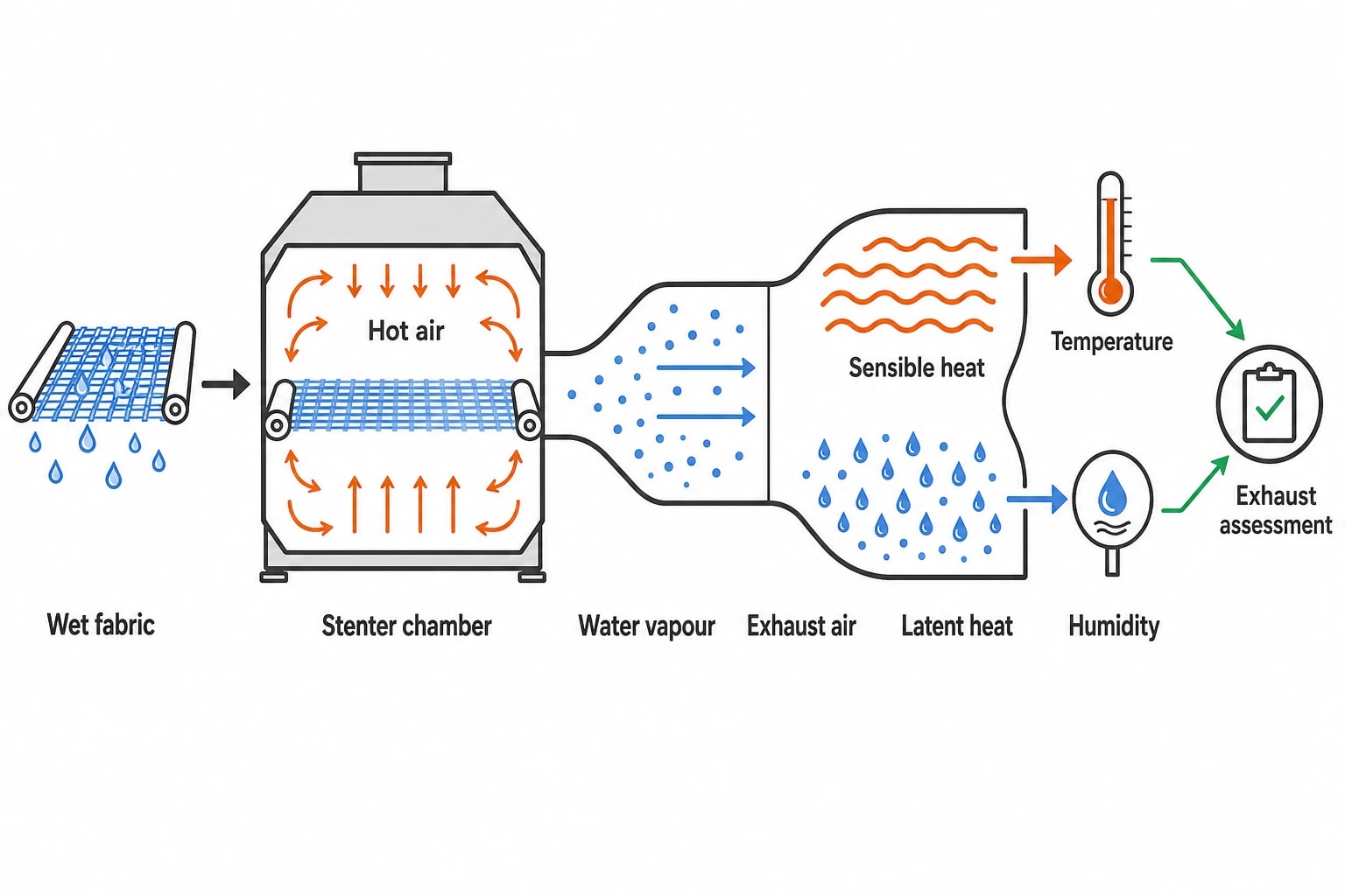
Stenters dry, heat-set, cure or thermosol fabric after dyeing, coating and finishing. Their chambers heat substantial volumes of air while the fabric releases water vapour. The exhaust system removes moisture, combustion products and process emissions from the machine.
The exhaust contains sensible heat in the air and latent heat associated with water vapour. Recovery is therefore more complex than a stack-temperature reading.
High exhaust temperature alone does not establish a viable project. Excessive fresh-air intake, poor recirculation control or unnecessary exhaust flow can create a large hot-air stream before it reaches a heat exchanger. The audit must determine whether the stenter needs that airflow for fabric quality, safety and emissions management.
Energy intensity needs production context
A site gas bill cannot show whether a stenter is becoming more efficient. Product mix, fabric weight, wet pick-up, width, line speed, drying temperature and downtime all influence consumption.
A useful textile-industry energy-efficiency baseline assigns energy to the stenter and relates it to the material processed. MWh/t is a useful management measure, and the EU BAT conclusions give an indicative yearly range of 0.5 to 4.4 MWh/t for thermal treatment. Mills should interpret that range carefully. A heavyweight coated textile, a wet dyed cotton fabric and a lightweight polyester fabric do not present the same drying load.
Create baselines by product family or process route. Record the operating variables that explain variation, including:
- Fabric type, mass per unit area and width
- Wet pick-up or inlet moisture
- Line speed and throughput
- Zone temperatures and actual temperature profile
- Exhaust temperature, humidity and flow
- Fuel input and fan electricity
- Recirculated-air proportion
- Finished-fabric moisture target
This evidence separates genuine efficiency improvement from a favourable change in throughput or product mix.

Identify where your plant is losing energy and quantify the savings potential — our audits map every heat source, sink, and waste stream in your facility.
What a stenter heat-recovery audit should measure
Establish the source before selecting equipment
The audit begins with a heat and mass balance around the stenter. Portable instruments, production records and existing control-system data can establish the condition of the exhaust and the process producing it.
Measurements should cover representative shifts and product runs. A short test on one straightforward fabric can overstate annual heat availability or hide the fouling conditions that determine maintenance effort.
The measurement plan should capture:
- Exhaust-air temperature, humidity, static pressure and flow
- Fresh-air intake and recirculation rate
- Gas, steam or thermal-oil heat input
- Exhaust and circulation fan electrical demand
- Fabric inlet and outlet moisture
- Line speed, width and mass throughput
- Zone setpoints and actual conditions
- Exhaust composition where oils, resins, softeners, lint or volatile compounds are present
The result is a measured operating envelope rather than a design-point estimate.
Identify a heat sink with matching demand
Recovered heat has value only when another process can use it. In textile wet processing, likely heat sinks include dye-house make-up water, washing water, boiler feedwater and incoming stenter air.
The heat sink needs a sufficiently low inlet temperature, demand at the same time as the stenter runs, and a clear connection to displaced purchased energy. A batch dye-house load may have a good temperature fit but poor hourly coincidence with a continuously operating stenter. A hot-water buffer vessel can bridge some of that mismatch, but the assessment must include tank heat losses, controls, space and cleaning access.
A 2024 study comparing stenter recovery arrangements found that hot-water generation could be less economic where dyeing-process hot-water demand was low. A heat exchanger should serve the mill’s real operating programme, not a nominal load on a supplier datasheet.
Calculate net benefit, including fan and pump energy
Lint, fibres, oils, waxes, softeners and condensable compounds can foul heat-transfer surfaces. Cooling the exhaust can also produce contaminated condensate. Heat-exchanger selection therefore depends on duct condition, drainage, filtration, inspection doors and safe cleaning access.
Pressure loss deserves equal attention. Filters, exchanger surfaces and additional ductwork can increase fan power. Run-around systems add pump electricity. The project appraisal should distinguish gross recovered heat from net energy reduction after electrical penalties and expected maintenance requirements.
Stenter heat-recovery configurations
Air-to-water recovery for process-water loads
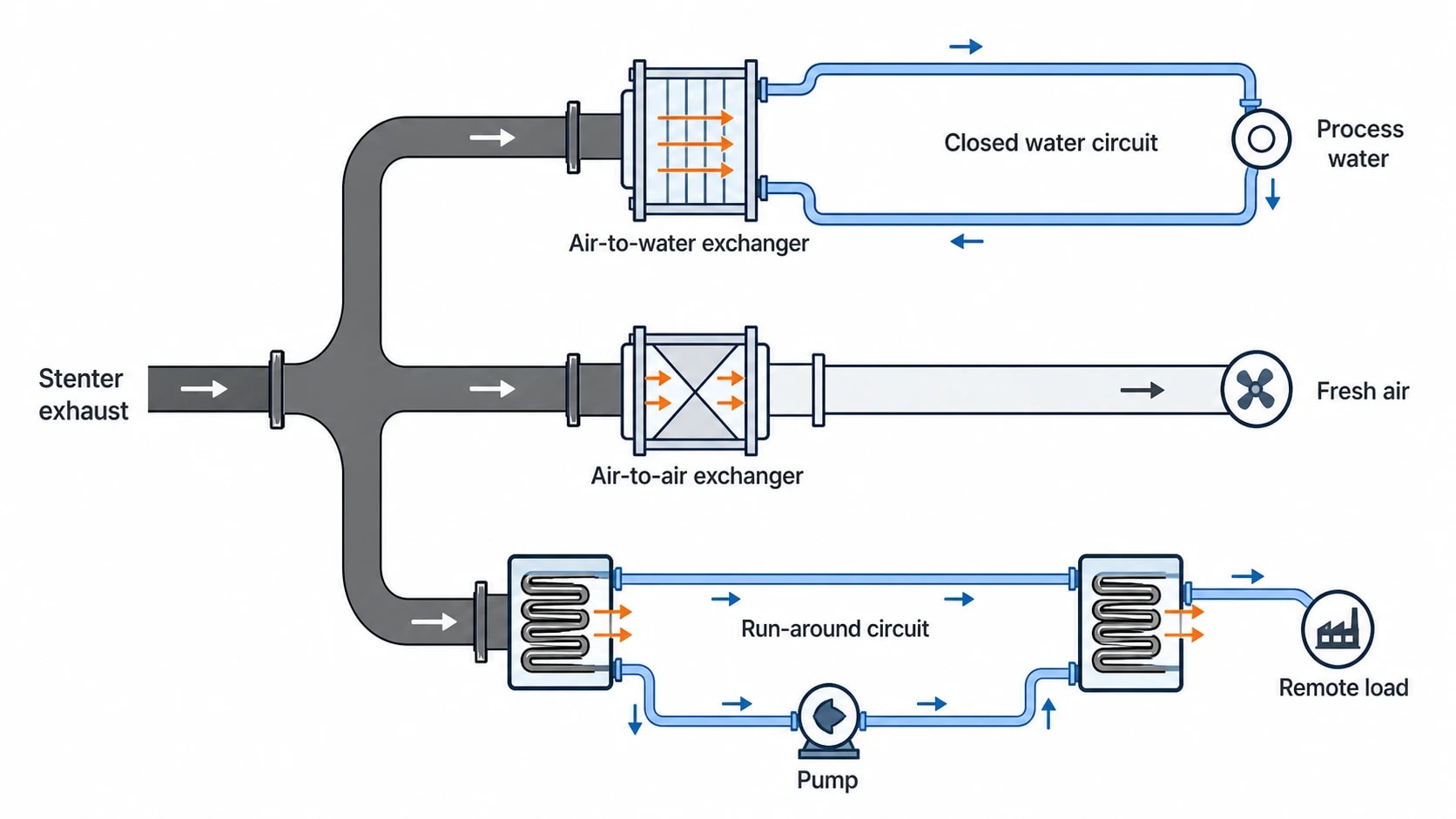
An air-to-water heat exchanger transfers heat from the stenter exhaust to a closed water circuit. The circuit can preheat process water for washing, dyeing or similar duties, often through a buffer vessel and secondary heat exchanger.
This arrangement keeps contaminated exhaust separate from process water. Its value depends on water flow, inlet temperature, hot-water demand during stenter operation and the heat exchanger’s cleaning regime. Water quality also affects the secondary side.
Air-to-air recovery for fresh-air preheating
Air-to-air recovery transfers exhaust heat to incoming fresh air. It can reduce direct burner duty and is particularly relevant where a mill has limited use for recovered hot water.
The design must control cross-contamination and preserve the stenter’s required exhaust capacity. Duct layout, pressure balance and heat-exchanger integrity matter because process fumes must not enter the production area or affect fabric quality.
Indirect run-around circuits for remote loads
A run-around circuit uses a pumped heat-transfer fluid between coils at the exhaust source and the heat sink. It can suit constrained mill layouts where the stenter and useful load are separated.
This flexibility carries a temperature penalty and introduces pump demand, pipework, maintenance points and freeze-protection requirements where relevant. The best option delivers reliable annual recovery at the required process conditions.
| Recovery route | Typical use | Critical audit checks |
|---|---|---|
| Air-to-water exchanger | Process-water preheating | Demand profile, water temperatures, fouling, buffer storage |
| Air-to-air exchanger | Stenter fresh-air preheating | Cross-contamination, pressure loss, exhaust balance, duct space |
| Indirect run-around circuit | Remote air or water load | Pump electricity, temperature approach, pipe route, maintenance access |

Identify where your plant is losing energy and quantify the savings potential — our audits map every heat source, sink, and waste stream in your facility.
Optimise the stenter before sizing recovery equipment
Reduce avoidable moisture upstream
Mechanical dewatering reduces the water that the stenter must evaporate. Squeezing, vacuum extraction and well-maintained rollers can lower wet pick-up before the fabric enters the dryer.
Commission Implementing Decision (EU) 2022/2508 identifies mechanical dewatering and avoiding overdrying as BAT 13 techniques for thermal treatment. Reducing the moisture load cuts heat demand immediately and avoids sizing recovery equipment around a preventable loss.
Match exhaust flow to the drying load
A stenter needs adequate exhaust to remove moisture and maintain the required operating conditions. Excess extraction sends more heated air outside and increases burner demand.
BAT 13 identifies advanced process monitoring and drying control, including inlet and exhaust humidity, air and fabric temperatures, residual moisture and adjustment of exhaust airflow. Exhaust humidity measurement and variable-speed fan control can help operators align extraction with the drying load.
Each product family needs validated operating limits. Operators also need a practical override procedure for starts, stops and unusual finishes. Stable residual moisture and fabric appearance remain the operating constraints.
Review recirculation, zones and heat losses
Recirculation reduces the cold fresh air that needs heating, subject to product, safety and emissions requirements. Zone temperatures should match the material and finish in production. Repeated use of a high setpoint as a margin can indicate poor sensing, weak control or maintenance problems.
Thermal imaging can identify damaged insulation, hot ducts, leaking access doors and failed seals. These repairs often involve less disruption than a major recovery installation and should be addressed before final capital sizing.
Regulation gives the audit a clearer structure
EU BAT 11 requires plans, targets and annual follow-up
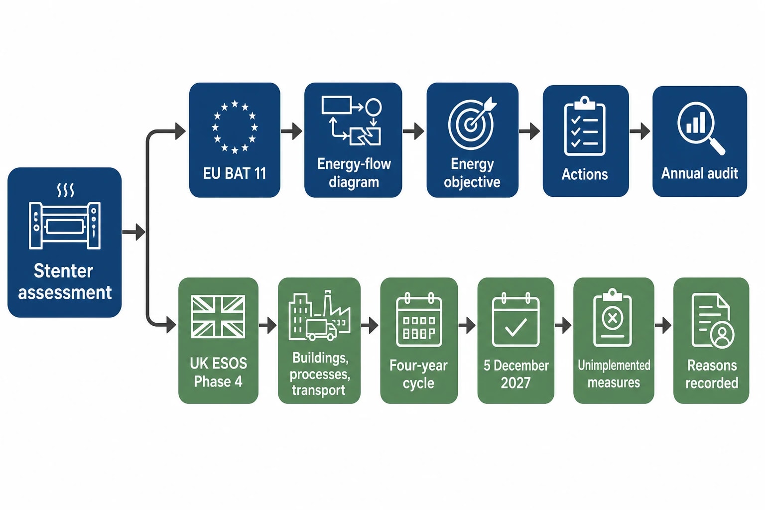
Commission Implementing Decision (EU) 2022/2508 sets BAT conclusions for the textiles industry under the EU Industrial Emissions Directive. BAT 11 specifies an energy-efficiency plan and audits as part of the environmental management system.
The plan includes energy-flow diagrams for plants and processes, objectives such as MWh/t of textile materials processed, and actions to achieve those objectives. BAT 11 states that audits should take place at least annually to check progress and follow through recommendations.
For UK mills, the decision does not replace UK permit conditions or ESOS duties. It remains a detailed technical reference for sites operating in the EU and mills supplying European production networks.
ESOS Phase 4 creates a UK compliance milestone
The Energy Savings Opportunity Scheme Regulations 2014, as amended, require qualifying large UK undertakings and groups to assess energy used in buildings, industrial processes and transport on a four-year cycle.
GOV.UK gives 5 December 2027 as the Phase 4 compliance-notification deadline. The current Phase 4 guidance requires organisations to report proposed measures that were not implemented and explain the reasons. A documented stenter assessment gives directors a firmer basis for recording a measure, approving it or recording why it was deferred.
A practical sequence for a stenter heat-recovery audit
Build the baseline and inspect the process
Start with utility records, production data, maintenance history and operating trends. Then assess the stenter, associated ductwork and likely heat sinks on site. Portable power analysers, thermal imaging and airflow, temperature and humidity measurements provide the data needed for a representative balance.
Test conservation measures before capital recovery
Evaluate upstream dewatering, exhaust-flow control, recirculation, zone setpoints, insulation and air leaks before heat-recovery equipment. These measures reduce the process load and establish a more stable operating point for heat-exchanger sizing.
Model the source and sink together
Test the recovery concept across representative production cases. The model should include exhaust conditions, heat-sink demand, process timing, heat-transfer limits, fouling allowance, pressure loss and auxiliary electrical demand.
The report should show annual fuel or steam displacement, additional electricity, carbon impact, maintenance needs, installation requirements and sensitivity to production hours. A project dependent on one fabric type or one seasonal hot-water demand profile requires that constraint to be explicit.
Plan installation and verify operation
Identify shutdown work, duct modifications, drainage, access requirements, controls integration and commissioning tests before approval. Production managers need a defined plan for what can be prepared during normal operation and what requires a planned stoppage.
After commissioning, measure fuel input, fan and pump electricity, relevant water temperatures and production throughput. Measurement and verification should use a documented boundary, baseline and adjustment method consistent with the International Performance Measurement and Verification Protocol.
This article reflects the independent analysis and editorial opinion of EnerTherm Engineering. Product names, trademarks, and brands mentioned belong to their respective owners. EnerTherm Engineering is not affiliated with, endorsed by, or a licensee of any third-party software or product mentioned unless explicitly stated.

Managing Director — EnerTherm Engineering
Dr. François Pierrel is Managing Director of EnerTherm Engineering with over two decades of expertise in thermal design, heat transfer, and industrial energy optimisation. He holds a PhD in Heat Transfer from Cranfield University and a Post-Doctorate from Heriot-Watt University.
