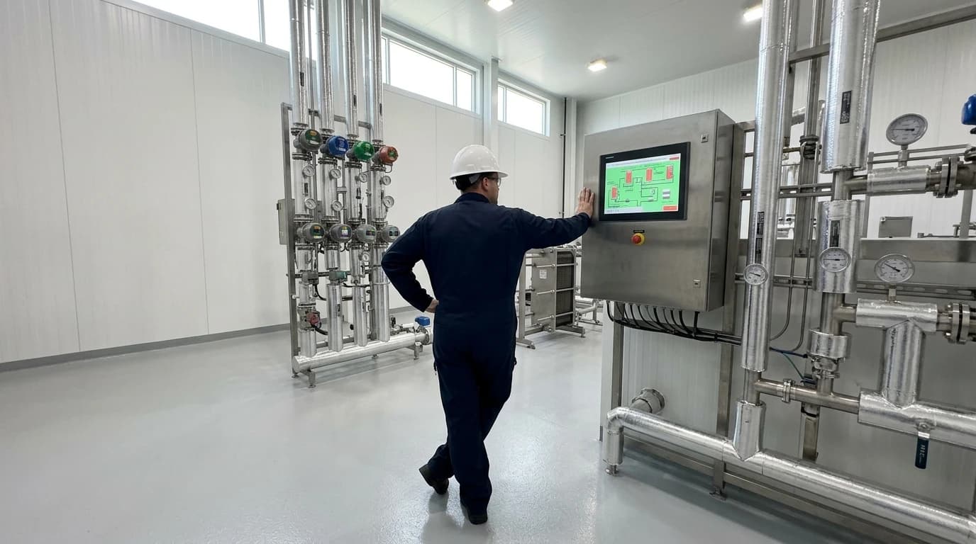
How UK Food Plants Recover Up to 95% of Pasteurisation Heat
How dual accumulator storage systems optimise pre-heating for boiler and CIP water.
Waste heat recovery in food processing captures thermal energy from hot process fluids, wastewater, or boiler exhaust to preheat incoming raw products, clean-in-place (CIP) water, or boiler feed loops. UK food and beverage plants operate some of the most energy-intensive thermal systems in manufacturing, where steam boilers, pasteurisers, ovens, and sterilisation retorts run continuously to ensure microbiological safety. Yet, much of this heat escapes through wastewater discharge, boiler blowdown, and flue gases.
By implementing process-integrated heat recovery systems, modern food plants can capture this lost energy. This article explains how engineers achieve a 90 to 95 per cent heat recovery rate in pasteurisation and how facilities can recycle low-grade waste thermal energy without risking contamination or violating strict food hygiene standards.

Identify where your plant is losing energy and quantify the savings potential — our audits map every heat source, sink, and waste stream in your facility.
Understanding Waste Heat Recovery in Food Processing
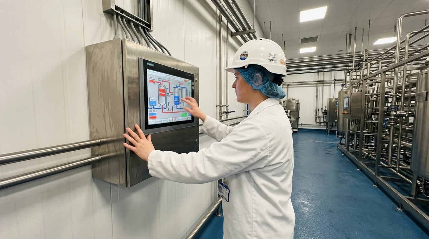
Industrial food and beverage production requires a delicate thermal balance. Processes must reach exact temperatures to eliminate pathogens, while downstream packaging lines require rapid cooling to preserve product quality and extend shelf life.
The Scale of Thermal Energy Consumption in Food Plants
Thermal energy represents a primary operating expense for UK food processors, with steam generation and hot water distribution consuming up to 60 per cent of a typical plant’s total energy budget. Traditional steam-raising boilers burn natural gas or fuel oil to produce steam above 140°C. This steam heats process water for pasteurisation, sterilisation, and CIP sanitisation. After transferring its heat, the condensed steam or hot effluent water is often discharged directly to the municipal sewer system, representing a massive loss of both water and thermal energy.
Why Pasteurisation Regenerators are Only the First Step
In modern industrial dairies and breweries, liquid pasteurisers use built-in thermal regeneration sections to transfer heat directly from the hot, pasteurised product back to the cold, incoming raw feed. While these internal loops recycle that thermal energy, they operate as closed systems that cannot address broader factory-wide thermal losses. High-temperature sterilisation lines, which consume 300 to 500 MJ per tonne of product, exhaust substantial amounts of high-grade heat. Similarly, boiler flue gases and continuous blowdown systems vent valuable energy directly into the atmosphere. Fully optimising a food plant requires capturing these external, non-integrated waste streams.
The Thermodynamic Principles of Regenerative Pasteurisation
To understand how food plants achieve these high thermal efficiencies, engineers must analyse the thermodynamic design of the pasteurisation loop. The entire process relies on rapid, high-velocity heat transfer within sanitary plate heat exchangers.
Operating Mechanics of Milk and Beverage Pasteuriser Regenerators
A typical High-Temperature Short-Time (HTST) pasteuriser consists of three primary zones: the heating zone, the holding tube, and the cooling/regeneration zone. In the regeneration section, cold raw product enters at approximately 4°C, flowing on one side of corrugated stainless-steel plates. On the opposite side, hot pasteurised product—having passed through the holding tube at 72°C—flows in a counter-current direction.
Calculating Heat Transfer and Thermal Savings
Process engineers calculate the thermal energy transfer rate (Q) within the regeneration section using the fundamental heat transfer equation:
Q=m˙⋅Cp⋅ΔT
Where:
Q is the thermal energy transfer rate in kilowatts (kW).
m˙ is the mass flow rate of the product stream in kilograms per second (kg/s).
Cp is the specific heat capacity of the fluid. For whole milk, this is approximately 3.89 kJ/kg·K, while for water-based beverages, it is 4.18 kJ/kg·K.
ΔT is the temperature change of the fluid across the regeneration section in Kelvin (K) or degrees Celsius (°C).
By maximising the surface area of the plates and maintaining high fluid turbulence, designers reduce the temperature approach (the difference between the exiting hot stream and entering cold stream). This thermodynamic design is what enables a regeneration efficiency of 90 to 95 per cent.
The Thermal Energy Deficit in Downstream Processing
Despite the efficiency of the internal pasteurisation loop, food processing plants still run a substantial thermal deficit. The pasteurisation system requires external heat from a utility stream, usually hot water or steam, to cover the final temperature rise from 65°C to 72°C. Furthermore, ancillary processes like CIP cleaning require massive volumes of water heated to 75°C to 85°C, which cannot be supplied by the pasteuriser itself. This creates an opportunity to capture external waste heat from sources such as refrigeration compressors, boiler flue gases, and wastewater systems to preheat these utility streams.

Identify where your plant is losing energy and quantify the savings potential — our audits map every heat source, sink, and waste stream in your facility.
Overcoming Hygiene and Compliance Barriers in Heat Recovery
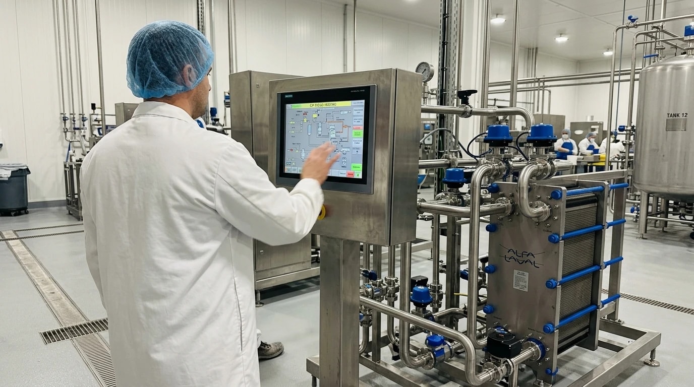
Integrating waste heat recovery systems into food processing requires strict adherence to hygiene standards. Unlike chemical plants or power stations, food factories cannot tolerate any risk of cross-contamination between waste streams and product streams.
Meeting BS EN 1672-2:2020 and BS EN ISO 14159:2008 Requirements
Every heat exchanger, pump, and pipe network in contact with food or utility water must comply with these standards. They dictate that all product-contact surfaces must have a maximum surface roughness value of Ra ≤ 0.8 µm to prevent bacterial attachment.
Furthermore, materials must resist corrosion. Thermal design teams typically specify 316L stainless steel or high-grade titanium alloys to withstand both corrosive food ingredients and aggressive acidic and alkaline CIP sanitisation chemicals. All joints must be continuously welded and ground smooth to eliminate crevices where pathogens such as Listeria or Salmonella could colonise.
Preventing Cross-Contamination with Double-Wall Boundaries
When recovering heat from highly contaminated waste streams, such as wastewater or anaerobic digestion digestate, a standard single-plate heat exchanger poses a contamination risk. If a plate pinhole or crack develops due to stress corrosion cracking, waste fluid can leak directly into the clean water line.
To prevent this, engineers install double-wall plate heat exchangers. These systems feature two plates welded or gasketed together, creating a narrow interstitial atmospheric channel between them. If either plate fails, the fluid leaks into this dry channel and drains externally, providing a highly visible indication of failure before any cross-contamination occurs.
Managing Hydraulic Pressures and Monitoring Systems
Another critical defence against contamination is hydraulic pressure management, ensuring that the clean fluid stream always operates at a higher hydraulic pressure than the waste or heating stream.
If a physical barrier fails, the higher-pressure clean water leaks into the lower-pressure waste stream, preventing pathogens or waste fluids from entering the clean system. Process engineers automate this safety loop using continuous differential pressure sensors. If the pressure difference drops below a safe threshold, the automation system immediately triggers an alarm, shuts down the wastewater pumps, and diverts the clean stream to a safe holding tank.
Multi-Stage Storage and Temperature Upgrading
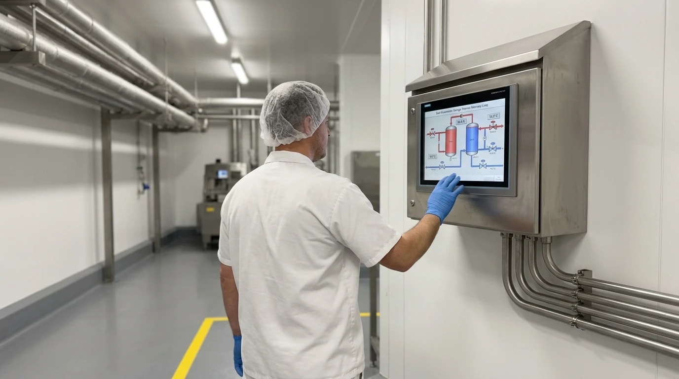
A major challenge of waste heat recovery is the temporal and thermal mismatch between heat sources and heat sinks. Wastewater discharge or pasteuriser operation often occurs on a batch basis, whereas boiler feed water makeup and CIP heating demands occur at different times. To bridge this gap, engineers deploy industrial heat pumps and dual accumulator storage systems.
Decarbonising Process Water with High-Temperature Industrial Heat Pumps
Low-grade waste heat, such as warm water from refrigeration compressors or washdown lines at 15°C to 25°C, is too cool for direct reuse in pasteurisation or CIP loops. To solve this, plants integrate high-temperature industrial heat pumps. These systems use vapour-compression cycles, often utilising natural refrigerants like CO₂ (R744) or ammonia (R717), to absorb heat from the low-grade stream and upgrade it to process hot water at 70°C to 90°C. This eliminates the need for steam heating, reducing a plant's dependency on gas boilers and significantly lowering Scope 1 carbon emissions.
Optimising Energy Flows with Dual HTA and LTA Accumulator Tanks
To manage fluctuating flows and temperatures, technical designs utilise a dual-reservoir thermal storage system consisting of a High-Temperature Accumulator (HTA) and a Low-Temperature Accumulator (LTA).
The LTA Reservoir: This tank collects low-grade waste streams, typically between 15°C and 45°C, such as final rinse waters, vacuum pump discharge, and air compressor cooling water. This thermal energy preheats cold incoming fresh water or boiler makeup water, raising it from a baseline of 5°C up to approximately 40°C.
The HTA Reservoir: This insulated vessel collects high-grade waste streams, typically between 60°C and 95°C, such as pasteuriser sterilisation dump water, continuous boiler blowdown, and retort cooling water. The HTA acts as a thermal buffer, holding hot water until it is required to preheat CIP rinse tanks or feed evaporator systems.
This thermal stratification ensures that high-grade heat is not degraded by mixing with low-grade wastewater, maintaining high thermodynamic exergy across the plant.
Accumulator TypeSource Fluid Temp RangePrimary Waste Heat SourcesTarget ApplicationLow-Temperature Accumulator (LTA)15°C to 45°CAir compressor cooling water, vacuum pump discharge, final CIP rinse waterPreheating boiler makeup water, initial heating of incoming fresh waterHigh-Temperature Accumulator (HTA)60°C to 95°CRetort cooling drains, boiler blowdown, pasteuriser sterilisation dumpsCIP preheating, feeding multi-effect evaporators, direct process water loops
Financial Offsets and Technical Auditing in the UK
Installing industrial heat recovery systems, heat pumps, and multi-accumulator networks requires a structured financial and technical evaluation. UK food manufacturers must balance the capital expenditure of these retrofits against long-term operational savings and carbon reduction targets.
Accessing the Industrial Energy Transformation Fund (IETF)
To offset the capital costs of deep decarbonisation projects, UK food processors can apply for funding through the government’s Industrial Energy Transformation Fund (IETF). The IETF provides grant funding for feasibility studies and the deployment of energy efficiency technologies, specifically supporting high-temperature industrial heat pumps and process waste heat recovery.
For example, large poultry processing sites in the UK have successfully secured IETF grants exceeding £600,000 to replace gas-fired steam loops with CO₂-based chiller heat recovery networks, demonstrating the commercial viability of these subsidised projects.
Implementing EnerTherm Engineering’s 7-Step Energy Audit Methodology
Before committing capital to a heat recovery project, a facility must undergo a rigorous thermal assessment. EnerTherm Engineering addresses this through its proprietary 7-step energy audit methodology:
Initial Consultation: Reviewing utility bills, historical energy consumption data, and mapping the plant's core thermal processes.
On-Site Assessment: Deploying portable, high-precision instrumentation—including power analysers, ultrasonic flowmeters, and thermal imaging cameras—to map actual energy flows and locate thermal leaks without disrupting production lines.
Data Analysis: Conducting thermodynamic mass and energy balances to pinpoint exactly where heat is lost and where it can be reused.
Opportunity Identification: Designing customised heat recovery loops, matching waste heat sources (such as effluent and boiler flue gas) with appropriate thermal sinks (such as CIP and boiler feed water).
Report Preparation: Generating a detailed, board-ready investment case with clear metrics on capital expenditure, Net Present Value (NPV), Internal Rate of Return (IRR), and simple payback periods.
Implementation Support: Managing the installation of sanitary heat exchangers, heat pumps, and accumulator tanks, ensuring full compliance with UK hygiene standards.
Ongoing Measurement & Verification (M&V): Tracking performance in compliance with the International Performance Measurement and Verification Protocol (IPMVP) to verify the achieved savings.
Through this methodology, food and beverage processing facilities achieve an average 18 per cent energy cost reduction and an 850-tonne annual CO₂e reduction.
Constructing a Board-Ready Financial Investment Case
A successful heat recovery integration must be backed by a robust financial model. When presenting these engineering projects to corporate boards, sustainability directors and utility engineers must highlight the dual benefits of reduced energy tariffs and carbon compliance. By matching IETF capital grants with the operational savings achieved through regenerative pasteurisation, most UK food plants can achieve a project payback period of 2 to 4 years. This rapid payback, combined with a permanent reduction in Scope 1 emissions, makes waste heat recovery one of the most effective paths towards achieving Net Zero in the food manufacturing sector.
This article reflects the independent analysis and editorial opinion of EnerTherm Engineering. Product names, trademarks, and brands mentioned belong to their respective owners. EnerTherm Engineering is not affiliated with, endorsed by, or a licensee of any third-party software or product mentioned unless explicitly stated.

Managing Director — EnerTherm Engineering
Dr. François Pierrel is Managing Director of EnerTherm Engineering with over two decades of expertise in thermal design, heat transfer, and industrial energy optimisation. He holds a PhD in Heat Transfer from Cranfield University and a Post-Doctorate from Heriot-Watt University.
