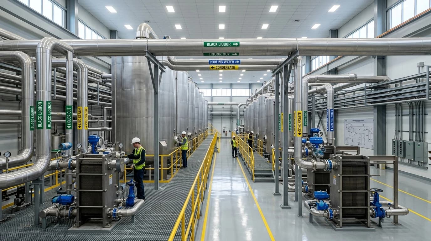
Pulp Mill Process Optimization Saves up to 14% Energy
Cutting Kraft mill CO₂ emissions by up to 2,800 tonnes via 11-step modelling.
Pulp mill process optimisation is a systematic engineering discipline that uses rigorous thermodynamic modelling, species-level mass balances, and process integration techniques to minimise thermal utility consumption and eliminate operational bottlenecks within integrated pulp and paper manufacturing facilities.
In modern pulping operations, mills face intense commercial pressures. Volatile fuel prices, strict carbon compliance targets under the UK Emissions Trading Scheme (UK ETS), and production bottlenecks in chemical recovery loops restrict mill profitability. Mill Directors and Process Engineering Managers must identify specific, risk-mitigated projects that guarantee energy and carbon reductions without interrupting continuous production.
Applying a structured heat and mass balance (HMB) framework yields significant operational improvements. Integrated pulp and paper mills can achieve an average energy reduction of up to 14%, a 1.8-year payback period, and an annual CO₂ reduction of 2,800 tonnes. This technical guide explains the engineering methodologies, thermodynamic principles, and process simulation workflows required to achieve these performance benchmarks.
The Thermodynamic Architecture of a Kraft Pulp Mill
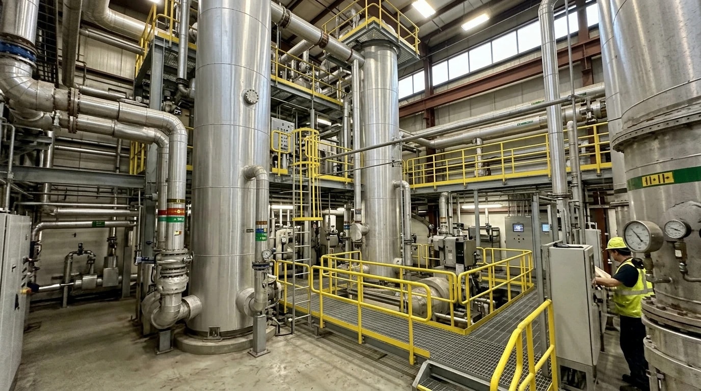
To optimise a pulp mill, engineers must treat the facility as a single, highly integrated thermodynamic system rather than a series of isolated unit operations. The Kraft process relies on a closed chemical and thermal loop.
The Chemical Recovery Loop and Steam Generation
The Kraft pulping process separates lignin from cellulose fibres by cooking wood chips in a hot, highly alkaline solution of sodium hydroxide and sodium sulphide, known as white liquor. This digestion process generates pulp and a waste stream called weak black liquor, which contains dissolved organic lignin and spent inorganic pulping chemicals.
To make the process economically viable, mills must recover these chemicals. The weak black liquor is concentrated and burned in a recovery boiler. This combustion serves a dual purpose: it recovers the inorganic chemicals as a molten smelt, which is processed back into white liquor, and generates high-pressure steam. This steam serves as the primary energy source for the entire mill, driving turbines to generate electricity and providing process heat.
Multi-Pressure Steam Header Complexity
Modern integrated mills utilise complex steam distribution networks with multi-pressure steam headers. These typically consist of high-pressure (HP) steam at 60 to 80 bar, medium-pressure (MP) steam at 10 to 15 bar, and low-pressure (LP) steam at 3 to 5 bar.
The HP steam generated by the recovery boiler expands through back-pressure or extraction steam turbines to generate electricity. Steam is extracted at MP and LP levels to supply thermal energy to various process consumers, such as the digesters, evaporator trains, and paper machine dryer sections. If the steam network is unbalanced, the mill must vent steam or let it down through pressure-reducing valves (PRVs) without generating power. Reconciling these steam headers is essential to maximise electrical output and avoid firing auxiliary utility boilers.

Map every energy and material flow in your process with detailed heat and mass balance calculations — the foundation for any optimisation or design project.
EnerTherm’s 11-Step Methodology for Pulp Mill Process Optimisation
Achieving repeatable energy savings of up to 14% requires a standardised, rigorous engineering framework. The 11-step methodology ensures that all design decisions are backed by validated data.
The methodology standardises the transition from raw site data to a fully executed energy-saving project:
| Step | Phase | Technical Objective |
|---|---|---|
| 1 | Discovery | Initial data acquisition from P&IDs, historical DCS logs, and site operational records. |
| 2 | Boundary Definition | Establishing control volumes around major thermal consumers and utility networks. |
| 3 | Field Validation | Conducting physical site surveys to measure temperature, pressure, and flow rates. |
| 4 | Baseline Development | Building a steady-state simulation model using advanced process simulation software. |
| 5 | Model Reconciliation | Reconciling species-level mass balances and thermodynamic energy balances. |
| 6 | Seasonal Calibration | Validating the model against summer, winter, and transition-period operating data. |
| 7 | Pinch Analysis | Mapping composite curves to identify pinch violations and heat recovery targets. |
| 8 | Debottlenecking Analysis | Identifying equipment constraints, such as recovery boiler or evaporator limits. |
| 9 | Scenario Modelling | Simulating specific optimisation projects to predict energy, water, and CO₂ savings. |
| 10 | Risk Mitigation | Evaluating project impacts on process safety, product quality, and operational stability. |
| 11 | Implementation Roadmap | Producing a single-source-of-truth Process Flow Diagram (PFD) and financial business case. |
Establishing the Single-Source-of-Truth PFD
The outcome of this 11-step framework is a single-source-of-truth Process Flow Diagram (PFD) with embedded stream tables, Sankey energy mapping, and validated mass and energy balances. This document provides mill operations teams and corporate directors with a shared, scientifically verified baseline. It eliminates guesswork when evaluating capital investments, ensuring that any proposed modification will perform as predicted under all seasonal and upset conditions.
Species-Level Mass Balances and Thermodynamic Validation
Pulp mill processes involve multi-phase streams containing fibres, dissolved organics, and inorganic salts. High-fidelity modelling requires tracking species-level mass balances. This includes accounting for non-process elements (NPEs) such as potassium, chloride, and calcium, which can accumulate in closed-loop systems and cause severe scaling or corrosion in heat exchangers and evaporators. Thermodynamic equations must be validated against actual plant measurements to account for heat transfer resistance caused by fouling.
Optimising the Black Liquor Recovery Cycle
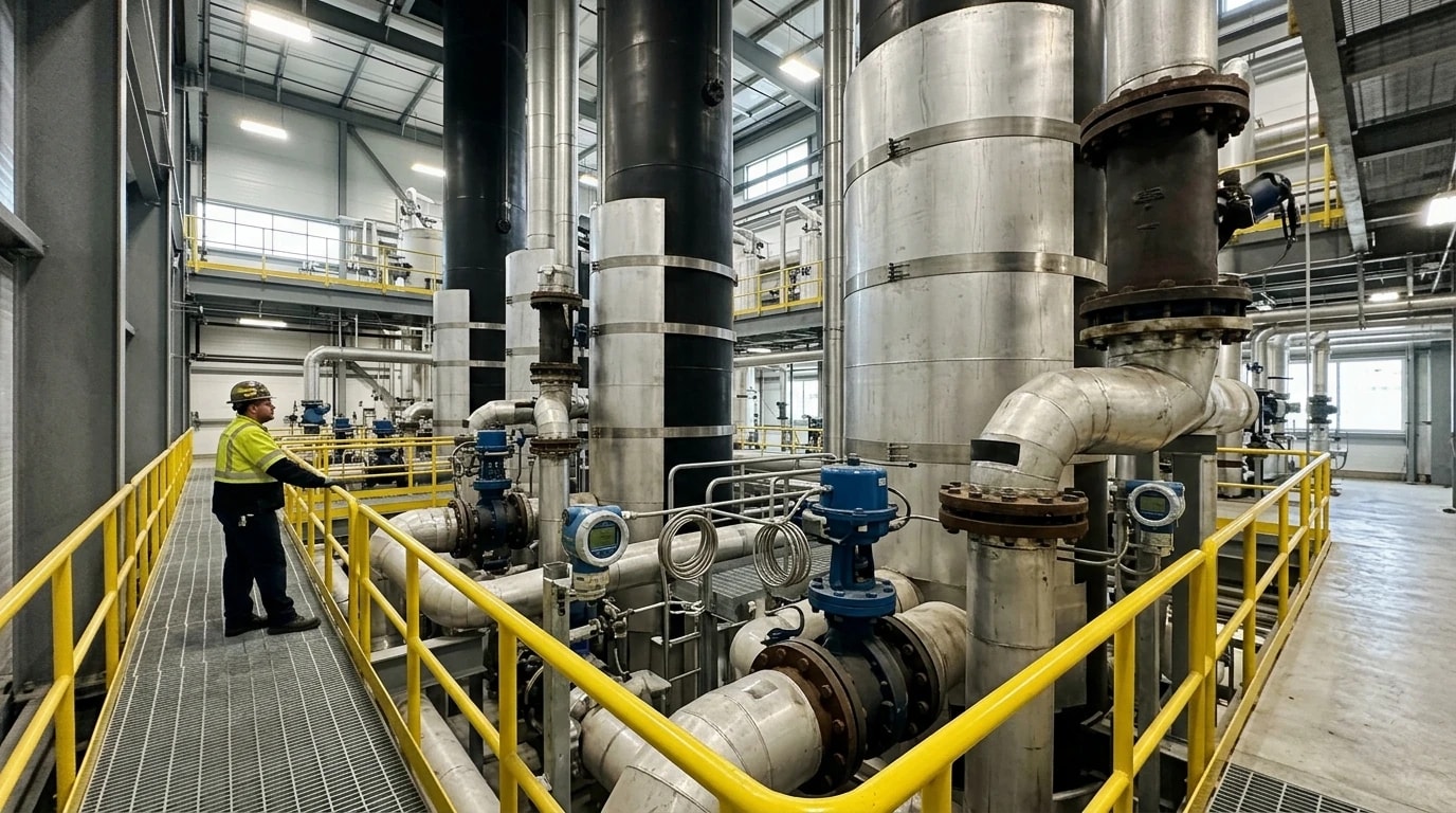
The black liquor recovery cycle is the most thermally intensive loop in a chemical pulp mill. Small efficiency gains here propagate throughout the entire facility, debottlenecking production and reducing fossil fuel reliance.
Multi-Effect Evaporator Trains
Weak black liquor leaving the brownstock washers typically has a dry solids content of 13% to 15%. To burn effectively in the recovery boiler, it must be concentrated to a heavy black liquor with a solids content of 65% to 75% or higher. This water removal occurs in a multi-effect evaporator train, which reuses vaporised water from one effect to heat the subsequent effect operating at a lower pressure.
The steam economy (E) of a multi-effect evaporator train represents the mass of water evaporated per unit mass of live steam consumed. It is defined by the following relation:
E=msteammevapwhere mevap is the total mass flow rate of water evaporated from the black liquor (kg/h), and msteam is the mass flow rate of live steam supplied to the first effect (kg/h).
In a standard six-effect evaporator train, typical steam economy values range from 4.8 to 5.5, meaning that every kilogram of live steam evaporates approximately five kilograms of water. Thermal design teams can improve this steam economy by:
- Integrating mechanical vapour recompression (MVR) on the pre-evaporators, which can reduce thermal energy consumption in the evaporator section by up to 90% by using electricity to upgrade the exergy of low-pressure vapour.
- Optimising the feed sequence and flash steam utilisation to maximise heat transfer.
- Mitigating boiling point rise (BPR) effects through precise liquor distribution and scaling control.
The Recovery Boiler and Biogenic CO₂ Emissions
The recovery boiler is the largest single energy producer and carbon emitter in the mill. A typical modern integrated Kraft pulp mill emits approximately 1.6 to 2.4 tonnes of biogenic CO₂ per Air-Dry tonne (t/ADt) of pulp from the recovery boiler alone.
Because these emissions originate from renewable biomass, capturing this carbon presents an opportunity for Bioenergy with Carbon Capture and Storage (BECCS), enabling pulp mills to operate as net-negative carbon facilities. However, chemical absorption systems, such as amine scrubbing, require significant thermal energy, typically 2.5 to 3.5 GJ of low-pressure steam per tonne of captured CO₂, for solvent regeneration. Process engineers must use pinch-point analysis to harvest low-grade waste heat from the flue gas and liquid streams to satisfy this thermal demand, avoiding the need to fire auxiliary, fossil-fuel-burning utility boilers.
Recausticising and Fossil CO₂ in the Lime Kiln
While the recovery boiler dominates biogenic emissions, fossil-fuel emissions in Kraft pulp mills are concentrated in the lime kiln within the recausticising circuit. The kiln heats calcium carbonate (lime mud) to temperatures exceeding 900 °C to regenerate calcium oxide (quicklime). This process typically emits 100 to 250 kg of fossil CO₂ per ADt of pulp.
To decarbonise the lime kiln, mill operators are evaluating several pathways:
- Biomass Gasification: Replacing fossil oil or natural gas with syngas generated from on-site wood waste or biomass.
- Hydrogen Burners: Integrating water electrolysers to produce green hydrogen, which can substitute fossil fuels in the kiln burner.
- Electric Rotary Kilns: Transitioning to fully electrified rotary kilns powered by low-carbon grid electricity.
Process integration is essential to ensure these alternative technologies do not create new thermal bottlenecks. For instance, drying the lime mud to a higher solids content (exceeding 70% to 75% solids) using hot flue gases before it enters the kiln directly reduces the thermal duty of the burner.
Maximising Thermal Efficiency in the Dryer Section
Once the pulp is bleached and prepared, it is formed into a sheet and dried. The dryer section of a paper or pulp machine is the largest steam consumer on the paper-making side of the mill, accounting for a significant portion of the total operating costs.
Cylinder-by-Cylinder Analysis and Condensate Evacuation
The dryer section consists of dozens of steam-heated rotary cast iron cylinders. Steam condenses on the inner walls of these cylinders, releasing its latent heat of vaporisation to the wet paper sheet.
Efficient heat transfer requires a detailed, cylinder-by-cylinder analysis of the steam condensation and condensate evacuation processes. As steam condenses, a layer of liquid condensate forms inside the cylinder. At high machine speeds, this condensate "rings" the cylinder due to centrifugal force, creating a significant thermal barrier.
Engineers must design and maintain high-performance rotary siphons and blow-through steam systems to continuously evacuate this condensate. By maintaining the correct differential pressure and steam blow-through rates, the condensate film thickness is minimised, reducing the thermal resistance and allowing lower-pressure steam to achieve the same drying rate.
Hood Exhaust and Heat Recovery Opportunities
Dryer sections are enclosed in large hoods to control the humidity and temperature of the drying air. Optimising hood operation involves balancing the exhaust air flow rate to maintain a high humidity level without causing condensation on the hood walls. High-humidity hoods reduce the volume of fresh air that must be drawn in and heated, saving steam.
Furthermore, integrating multi-stage heat recovery exchangers in the hood exhaust duct allows the recovery of low-grade heat. This recovered energy is used to:
- Preheat the incoming pocket ventilation (PV) air.
- Heat process water for the showers and stock preparation.
- Warm the machine room ventilation air during winter.
This cascading heat recovery design reduces the mill's overall steam demand, directly contributing to the energy savings target of up to 14%.

Map every energy and material flow in your process with detailed heat and mass balance calculations — the foundation for any optimisation or design project.
Closed-Loop Water Circuit and Filtrate Management
Pulping and bleaching require vast quantities of water to wash and transport fibres. However, water management is fundamentally linked to thermal energy efficiency.
White Water and Filtrate Loop Optimisation
Every cubic metre of cold fresh water introduced to the mill must be heated to process temperatures, typically 50 °C to 70 °C, using steam heat exchangers. Therefore, reducing fresh water consumption directly reduces steam demand.
Process engineers optimise water circuits by closing white water and filtrate loops. This involves:
- Reusing paper machine white water in the stock preparation and pulp dilution stages.
- Deploying counter-current washing systems in the bleach plant, where clean filtrate from the final bleaching stage is piped backward to wash pulp in the preceding stages.
- Reconciling species-level mass balances to ensure that closed-loop water reuse does not lead to the accumulation of dissolved organic matter, pitch, or non-process elements (NPEs) that can degrade paper quality or cause equipment scaling.
Through systematic water loop closure, a mill can significantly lower its fresh water intake, reducing both the thermal energy needed for water heating and the volume of warm effluent discharged to the wastewater treatment plant.
Process Simulation and Pinch Analysis Integration
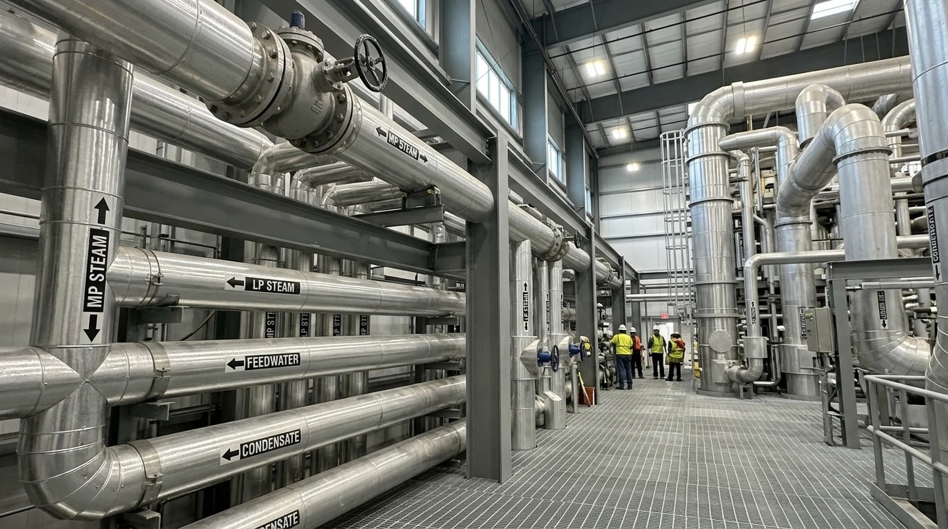
Simulating Complex Processes with Aspen Plus, HYSYS, and DWSIM
Process engineering teams targeting Kraft pulp mill energy and carbon reductions often combine baseline simulation models with thermal pinch analysis. When evaluating these projects, platforms such as Aspen Plus, HYSYS, and DWSIM provide the thermodynamic foundation to construct high-fidelity steady-state and dynamic models of the entire mill. These platforms utilise sophisticated thermodynamic property packages capable of modelling the non-ideal behaviour of black liquor, pulping chemicals, and volatile gases.
These models allow design teams to:
- Simulate different operating scenarios, such as changing species-level fibre inputs or modifying chemical charges.
- Predict the impact of process changes on steam generation and electrical output.
- Validate proposed equipment modifications under seasonal plant variations before capital is committed.
Heat-Exchanger Network Design via Aspen Energy Analyser
By coupling the base-case simulation with pinch analysis tools, such as Aspen Energy Analyser, engineers can construct hot and cold composite curves for the entire mill. These curves plot temperature against enthalpy for all process streams that require heating (heat sinks) and cooling (heat sources).
The point where the curves come closest to each other is the "pinch". Pinch analysis establishes the thermodynamic limits of heat recovery, identifying where high-temperature heat is being inappropriately used for low-temperature tasks (a pinch violation).
By redesigning the heat-exchanger network to eliminate these violations, engineers can maximise the recovery of low-grade heat and ensure that high-pressure steam is reserved for exergy-intensive tasks like power generation. This systematic thermal integration ensures that the recovery boiler's thermal energy is optimised.
The following diagram illustrates the integrated flow of black liquor concentration, steam generation, and multi-pressure steam distribution within an optimised Kraft mill:
Technical and Economic Performance Outcomes
Implementing a mill-wide pulp mill process optimisation project is not just an environmental initiative; it is a highly profitable capital investment.
Energy Savings and Carbon Reduction Metrics
Based on historical project performance, mills applying this systematic 11-step framework achieve these target energy and carbon reductions. For a typical integrated mill producing 300,000 tonnes of pulp per year, the up to 14% thermal energy reduction translates to tens of thousands of megawatt-hours of saved thermal energy.
Furthermore, this efficiency directly reduces greenhouse gas emissions. By eliminating the need to fire auxiliary natural gas or heavy fuel oil boilers, and by optimising lime kiln efficiency, mills achieve the projected 2,800 tonnes of annual CO₂ reduction. When combined with emerging BECCS technologies, this process optimisation acts as the foundation for achieving net-zero or negative-carbon pulp production.
CAPEX, OPEX, and Payback Analysis under UK ETS and Industrial Regulations
Under the UK Emissions Trading Scheme (UK ETS) and the Industrial Emissions Directive (Directive 2010/75/EU), industrial facilities face rising costs for carbon emissions. Minimising fossil fuel use directly reduces carbon tax liabilities and compliance costs.
The capital expenditure (CAPEX) required for these optimisation projects, which typically involves installing secondary heat exchangers, upgrading condensate recovery systems, or retrofitting evaporator effects, is offset by rapid operational expenditure (OPEX) savings. Project historical data confirms the 1.8-year payback period. This rapid return on investment, combined with guaranteed carbon compliance, makes mill-wide thermal optimisation one of the most low-risk, high-return capital projects available to Mill Directors today.
This article reflects the independent analysis and editorial opinion of EnerTherm Engineering. Product names, trademarks, and brands mentioned belong to their respective owners. EnerTherm Engineering is not affiliated with, endorsed by, or a licensee of any third-party software or product mentioned unless explicitly stated.

Managing Director — EnerTherm Engineering
Dr. François Pierrel is Managing Director of EnerTherm Engineering with over two decades of expertise in thermal design, heat transfer, and industrial energy optimisation. He holds a PhD in Heat Transfer from Cranfield University and a Post-Doctorate from Heriot-Watt University.
