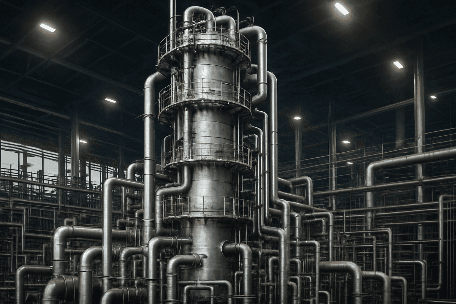
Stripping Column Design: Mastering Heat and Mass Balance
Stripping columns are essential separation tools used across chemical processing, wastewater treatment, food processing, pharmaceuticals, and solvent recovery. They remove volatile components from liquid mixtures by contacting the liquid with a vapour phase. Efficient stripping column design and operation depend on a sound heat and mass balance, appropriate vapour-liquid contact, and operating conditions that favour transfer of the target component into the gas phase.
What is a Stripping Column?
A stripping column, sometimes called a stripper column, is a vertical vessel used to remove one or more volatile components from a liquid feed. The liquid feed normally enters near the top of the column, while a stripping gas—often steam, air, nitrogen, or process vapour—enters at the bottom. The two phases flow counter-currently, maximising the driving force for mass transfer from the liquid to the gas phase.
A stripping column is the reverse of an absorber: in absorption, a liquid removes a component from a gas; in stripping, a gas removes a component from a liquid. Steam stripping is sometimes described as “scrubbing” a liquid feed, but a stripper column should not be confused with a gas scrubber.
| Feed location | Separation method | Energy input |
|---|---|---|
| Top of the stripping column | Volatile liquid components transfer into an upward-flowing gas | Often supplied by steam, heated gas, or a reboiler |
| Middle of a typical distillation column | Repeated vapourisation and condensation separate components | Usually higher because boiling and condensation duties are required |
The separation depends on vapour-liquid equilibrium and the difference between the component concentration in the liquid and its equilibrium concentration at the gas-liquid interface. More volatile components, higher temperature, lower pressure where practical, and sufficient stripping-gas flow generally improve removal.
Types of Stripping Columns
-
Packed Columns: These columns contain packing such as Raschig rings, Pall rings, random packing, or structured packing to increase gas-liquid interfacial area. They are often selected for low pressure drop, vacuum operation, corrosive duties, and relatively clean liquid feeds.
-
Tray Columns: These columns use sieve, valve, or bubble-cap trays to facilitate staged gas-liquid contact. Trays can be easier to inspect and may be preferable where solids, fouling, or a wide operating range must be accommodated.
-
Air Stripping Columns: Air is forced through contaminated water to transfer volatile organic compounds (VOCs), dissolved gases, and some ammonia into the air stream. The off-gas may require treatment before release.
-
Steam Stripping Columns: Steam is used to strip volatile components from a liquid stream. It is particularly useful when reduced partial pressure improves removal, and when air would create oxidation, flammability, or downstream recovery concerns.

Map every energy and material flow in your process with detailed heat and mass balance calculations — the foundation for any optimisation or design project.
Applications of Stripping Columns
Stripping columns find use in a wide range of applications:
-
Wastewater Treatment: Removing VOCs, hydrogen sulphide, dissolved gases, and ammonia from wastewater.
-
Solvent Recovery: Recovering valuable solvents from process streams or reducing solvent content before downstream treatment.
-
Deaeration of Liquids: Removing dissolved gases such as oxygen and carbon dioxide from boiler-feed water, process water, and product streams.
-
Food Processing: Deodorising and refining fats and oils while limiting the loss of valuable flavour, aroma, or nutritional components.
-
Pharmaceutical Manufacturing: Reducing residual solvents and enhancing the purity of liquid products or intermediates.
-
Environmental Control: Removing contaminants from liquid streams before discharge, recycle, biological treatment, or further polishing.
Heat and Mass Balance: The Core Principles
Heat and mass balance calculations are fundamental to stripping column design and operation. They establish the required stripping-gas rate, liquid product flow, component removal, heat duty, and utilities. A reliable balance also provides the basis for sizing the column diameter, estimating packing height or tray count, and checking whether the target outlet specification is realistic.
Mass Balance
Mass balance ensures that the mass entering a process equals the mass leaving, allowing for generation, consumption, and accumulation where these apply. For a steady-state stripping column without chemical reaction, with the stripping medium included within the column boundary, the overall balance is:
F+S=L+Vwhere F is the liquid feed flow rate, S is the stripping-gas or steam inlet flow rate, L is the bottoms liquid flow rate, and V is the overhead vapour flow rate. If stripping steam condenses within the column and leaves in the bottoms, that condensate is included in L.
For a component being stripped:
Fzi+Ssi=Lxi+Vyiwhere zi and si are the component fractions in the feed and stripping medium, respectively, while xi and yi are the component fractions in the liquid outlet and overhead vapour.
If an overhead condenser is included within the chosen system boundary, its condensate must be shown as a separate outlet stream, for example:
F+S=L+D+Gwhere D is overhead condensate and G is the uncondensed vent gas. The corresponding component balances must use the composition of each outlet stream.
In practice, balances should be prepared for the total flow and for each significant component, including water, stripping steam or air, the target volatile compound, and any non-condensable gases. If steam condenses into the liquid or volatile liquid components evaporate appreciably, the corresponding phase-flow changes must be included rather than assumed constant.
-
Overall Mass Balance: Total mass in equals total mass out at steady state.
-
Component Mass Balance: For each component, the quantity entering with the feed and stripping medium equals the quantity leaving in the gas, liquid, and any condensate streams.
-
Removal Efficiency: The required removal should be expressed as both an outlet concentration and a percentage removal. A high percentage removal alone can be misleading when the feed concentration is variable.
Energy Balance
An energy balance, also known as a heat balance, tracks energy entering and leaving the system. It is particularly important in steam stripping column design because live steam, reboiler duty, feed preheating, overhead condensation, and heat losses can dominate operating cost.
For a steady-state column, a simplified energy balance is:
∑m˙inhin+Q=∑m˙outhout+Qlosswhere m˙ is mass flow rate, h is stream enthalpy, Q is heat added to the column, and Qloss is heat lost to the surroundings.
Key considerations for energy balance in a stripping column include:
-
Heat Input: Heat added through live steam, a reboiler, feed preheating, or another heating method.
-
Heat Output: Heat removed through overhead condensation, cooling, hot bottoms liquid, or vented vapour.
-
Heat Losses: Heat lost to the environment through radiation and convection. These can be material for uninsulated equipment or small units operating at elevated temperature.
-
Enthalpy Changes: Changes in enthalpy caused by sensible heating, vapourisation, condensation, pressure changes, and chemical reactions where relevant.
-
Condensate Handling: In steam stripping, determine whether condensed steam leaves with the bottoms liquid, is separated downstream, or is returned as condensate. This affects both the material and heat balance.

Map every energy and material flow in your process with detailed heat and mass balance calculations — the foundation for any optimisation or design project.
Performing Heat and Mass Balance Calculations
Heat and mass balance calculations involve applying the relevant balances to the column and its associated equipment, such as feed heaters, reboilers, condensers, reflux drums, vent systems, and off-gas treatment. The resulting equations can be solved manually for straightforward duties or with process simulation software for non-ideal, multicomponent systems.
Steps for Performing Heat and Mass Balance
-
Define the System: Clearly define the boundaries of the system being analysed. Decide whether the balance covers the stripper column alone or the complete stripping system, including condensers and off-gas treatment.
-
Identify Inputs and Outputs: Identify every stream entering and leaving the system, including composition, temperature, pressure, phase, flow rate, and relevant physical-property data.
-
Set the Separation Target: State the required liquid-outlet concentration, removal percentage, recovery target, and any limit on overhead emissions or condensate contamination.
-
Write Balance Equations: Write overall and component mass balances, followed by an energy balance. Include steam condensation, dissolved gases, heat losses, and any reaction or neutralisation where applicable.
-
Apply Equilibrium and Mass-Transfer Data: Use appropriate vapour-liquid equilibrium data, Henry’s law data for dilute systems, or a validated thermodynamic model. Do not assume ideal behaviour for strongly non-ideal, electrolytic, or high-pressure systems.
-
Solve the Equations: Solve the equations simultaneously to determine unknown flow rates, temperatures, duties, and compositions. This may require process simulation software.
-
Validate the Result: Check that calculated vapour and liquid loads are hydraulically feasible, that the predicted outlet specification is achieved, and that utilities, materials of construction, and downstream treatment are suitable.
Software Tools for Heat and Mass Balance
Several software tools can aid in performing heat and mass balance calculations:
-
Aspen HYSYS: Comprehensive process simulation software used for designing and optimising chemical processes.
-
FlowBal: Software specifically designed for heat and mass balance calculations.
-
HSC Chemistry: Software that calculates real or constrained heat balances, given mass balances as boundary conditions.
-
Other Spreadsheet Programs: Spreadsheets can be effective for transparent preliminary calculations, sensitivity studies, and routine operating balances, provided the assumptions and physical-property data are clearly documented.
For a detailed stripper column, simulation should be supported by plant data or pilot data wherever possible. The thermodynamic model must suit the system: aqueous VOC stripping, ammonia stripping, hydrocarbon service, and steam deodorisation do not behave in the same way.
Design Considerations for Stripping Columns
Several design parameters must be considered to optimise the performance of a stripping column:
-
Column Height and Diameter: Diameter is determined primarily by vapour and liquid hydraulic loading, pressure drop, entrainment, and flooding margin. Height is determined by the required number of equilibrium stages or transfer units, packing efficiency, and the separation target.
-
Packing Material: The type, size, surface area, wettability, and material of construction influence interfacial area, pressure drop, liquid distribution, and mass-transfer rate. Structured packing often offers low pressure drop, while random packing may be economical and tolerant of variable operating conditions.
-
Tray Design: Tray spacing, active area, weir height, downcomer design, hole area, and turndown affect gas-liquid contact and mass-transfer efficiency.
-
Liquid Distribution: Packed-column performance depends heavily on even liquid distribution. A poor distributor can cause channelling and leave packing under-wetted, even when the calculated packing height is adequate.
-
Operating Conditions: Temperature, pressure, feed condition, and vapour and liquid flow rates affect equilibrium, mass-transfer driving force, utility use, and hydraulic performance.
-
Materials of Construction: Corrosion, temperature, pressure, chloride content, acidity, caustic concentration, and solvent compatibility should be considered early. Corrosion allowance alone is not a substitute for appropriate metallurgy.
Optimising Operating Conditions
-
Temperature: Higher temperatures can increase component volatility and improve stripping, but may also increase energy use, degrade heat-sensitive products, cause foaming, or promote unwanted side reactions.
-
Pressure: Lower pressure can enhance volatility, particularly for high-boiling or heat-sensitive materials. However, vacuum systems increase capital cost, can introduce air leakage, and may require larger vapour-handling equipment.
-
Flow Rates: Set liquid and gas flow rates from the required separation and hydraulic limits. The liquid-to-vapour ratio, L/V, affects the operating line, stripping driving force, column diameter, and utility consumption.
-
Stripping Medium: Steam provides heat and lowers the partial pressure of volatile components, but adds water that may need to be condensed or treated. Air avoids steam generation but can create a larger off-gas stream and may be unsuitable for flammable or oxygen-sensitive service.
-
Feed Conditioning: Preheating the feed can reduce reboiler duty and improve volatility. Removing solids or oils upstream may prevent fouling, distributor blockage, and poor mass transfer.
A practical stripping column design should be tested against normal, minimum, and maximum feed rates and compositions. The column must avoid flooding at maximum load while maintaining sufficient wetting, vapour contact, and separation performance at turndown.
Troubleshooting Stripping Columns
Common issues and troubleshooting strategies for stripping columns include:
-
Flooding: Excessive liquid or vapour flow can cause a rapid pressure-drop increase, entrainment, unstable levels, and reduced separation efficiency. Check actual flow rates, foaming tendency, tray condition, packing fouling, and downstream pressure restrictions.
-
Channelling: Uneven liquid or gas distribution can reduce phase contact. Inspect liquid distributors, redistributors, inlet devices, packing settlement, and liquid maldistribution.
-
Fouling: Buildup of solids, scale, polymers, biological growth, or other contaminants can reduce efficiency and increase pressure drop. Review feed filtration, pretreatment, cleaning arrangements, and temperature conditions.
-
Foaming: Foaming can reduce capacity, promote entrainment, and cause unstable operation. Identify surfactants or contaminants, review antifoam compatibility, and avoid abrupt hydraulic changes.
-
Poor Removal Performance: Confirm the feed composition and flow, stripping-gas rate, temperature, pressure, analyser calibration, vapour-liquid equilibrium assumptions, and the condition of trays or packing.
-
High Steam Consumption: Check feed temperature, insulation, steam quality, reboiler performance, condensate handling, excessive reflux or cooling, and whether the specified outlet concentration is tighter than necessary.
Heat and Mass Balance in Specific Applications
Wastewater Treatment
For VOC air stripping, the balance should set the air-to-water ratio, hydraulic loading, off-gas contaminant concentration, and the capacity of the selected emissions-control system. EPA guidance identifies air-to-water ratios of 10:1 to 100:1 as a typical design range for aqueous VOC stripping, subject to contaminant volatility and the required effluent concentration. For ammonia stripping, pH is a primary design variable: EPA guidance specifies adjustment to pH 10.8–11.5 to convert ammonium to free ammonia and gives typical packed-depth criteria of 6.1–7.6 m for air-stripping towers. EPA air-stripping guidance EPA ammonia-stripping fact sheet
Food Processing
In edible-oil deodorisation, the balance should track stripping-steam rate, vacuum load, residence time, oil temperature, removed free fatty acids and odour compounds, and the cooling duty needed before product handling. The American Oil Chemists’ Society notes that most edible oils are deodorised at 230–260°C; the selected temperature, pressure, steam rate, and residence time must meet deodorisation requirements while limiting thermal damage. AOCS deodorisation guidance For vegetable oils, Codex guidance identifies deodorisation at 190–230°C as an option to reduce formation of glycidyl esters, with the applicable conditions depending on the oil and equipment. FAO/WHO Codex report
Solvent Recovery
For solvent recovery, the design basis should specify residual solvent in the stripped liquid, solvent recovery to the product system, steam consumption, condenser duty, vent composition, and recovered-solvent purity. Where water and solvent form separate liquid phases after condensation, the balance must include the decanter split and the solvent dissolved in the aqueous phase; where they do not, the required downstream separation must be included. Condensing temperature and non-condensable-gas load determine both condenser sizing and solvent losses through the vent system.
